ANALYSIS OF THE EFFECT OF DIFFERENT LASER BEAM TECHNOLOGY PARAMETERS WHEN CUTTING STAINLESS STEEL SHEETS WITH YTTERBIUM FIBER
LASER MACHINE
Miklós Berczeli1*, Gábor Marsi1
1 Department of Innovative Vehicles and Materials, GAMF Faculty of Mechanical Engineering and Computer Science, John von Neumann University, Hungary
https://doi.org/10.47833/2021.1.ENG.015
Keywords:
laser
stainless steel cutting
materials technology Article history:
Received 30 March 2021 Revised 28 April 2021 Accepted 10 May 2021
Abstract
There are many ways to use laser cutting in the industry. Many parameters affect the quality of the cut, which is a complex process. The study focuses on a small group of these parameters. A laser beam test was performed on a DURMA HD- FS 3015 YLS-4000 - 4 kW ytterbium fiber laser machine, during which the parameters used when cutting various stainless materials are tested in order to achieve the best possible cut in order to optimize the process.
The device is capable of delivering 4 kW of power when cutting, which allows the cutting of stainless steel sheets up to a maximum thickness of 10 mm. The parameter test is 1; 1.5; 2; 3;
4; 5; 6; and on 8 mm thick stainless steel plates.
1 Introduction
Nowadays, sheet metal processing has become an outstanding industrial sector in Hungary.
The main reason for this is the presence of large car manufacturers, whose smaller companies dealing with sheet metal processing participate in the role of suppliers. A priority area for these machining is when precise cutting of stainless steel sheet materials is required. Here, in addition to traditional cutting methods, modern cutting methods must be used, the operation of which is economically maximized both in terms of the machine and in terms of the yield of the raw material [1,2]. There are a number of conditions to consider during laser cutting, some of which are:
laser beam power, power density of the laser beam, the focal length of the focusing lens, material and thickness of the plate to be cut, the distance between the cutting gas nozzle and the surface of the plate, the position of the axis of the laser beam relative to the surface normal of the plate [3-7].
Stainless steel sheets are cut by a variety of mechanical and thermal processes. Cutting with conventional sheet metal shears is a cheap and dirt-free solution, but there are several limitations to its applicability. One of the major disadvantages is the direct mechanical stress, which also causes tool edge wear. As the thickness of the plate increases, more and more robust machines would be needed, which significantly increases the cost. The physical properties of steels with different properties should be taken into account when determining the cutting technology, because higher cutting forces have to be applied than stainless steels compared to non-alloy steels. The different mechanical properties of stainless steel, the value of higher shear stress, similarly influence punching and punching technologies [8-10].
With high-power lasers, stainless steel sheets could be cut easily and formed an oxide-free cutting surface using nitrogen auxiliary gas. Although, in many cases, a secondary deburring procedure was also required in many cases, as the laser slowed down at sharp corners. To eliminate this, cutting parameters should have been changed, such as reducing speed, power, and frequency
at such corners. However, this meant a lot of extra time in programming, so in the end they decided to deburr after cutting [11-13].
When stainless steel is machined, the laser melts the steel and then the auxiliary gas, in this case nitrogen, removes the molten metal. This process results in an oxide-free surface. Here, however, it is extremely important to pay attention to speed, sharp corners, and the accuracy of the laser focus. If any fault occurs, nitrogen and molten steel form plasma. Plasma detection eliminates this and prevents incorrect machining of the workpiece by reducing the feed rate [14,15].
2 Experimental
2.1 Materials
To optimize the cut, the used material was 1.4301 (KO33) X5CrNi18-10. The use of stainless materials in these products is essential, as it is also considered a food industry, and strict requirements must be met. KO33 is a relatively inexpensive, widely used material within stainless materials. As it is an austenitic steel, it has favourable mechanical properties, it can be formed and machined excellently when hot and cold, and its welding does not require a more complicated work schedule. With its surface finish, it gives the products a very aesthetic appearance, which it retains for almost indefinitely without additional protection.
2.2 Laser machine
The DURMA HD-FS laser is a high speed 2 dimensional cutting table for cutting flat plates. It operates according to the flying optics principle, which means that the plate is fixed to the cutting table and the cutting head moves in the X and Y directions and performs the cutting. With this method, extremely high (on the order of 3G) acceleration can be achieved and cutting can be performed with maximum accuracy using a direct measuring system. The beam source is a YLS- 4,000, 400 to 4,000 W adjustable beam source with a wavelength of 1,070 nanometers. A Precitec cutting head was used for cutting. The ceramic part located on the nozzle protects the cutting head from damage, which can occur, for example, in accidents where the cutting head hits the cut plate or the plate rotates unexpectedly during cutting.
2.3 Test specimen
First the test specimens’ unique geometry were determined so that it had sharp corners and rounding so that the cut from can be examined as many angles and views as possible. Using this test path the typical shapes’ of the working samples can be examined during the investigation. The cross-shaped cut-out is relatively small, so the machine has to work there with great dynamics and many changes of direction (Figure 1).
Figure 1. The test geometry for the laser-cutting test to examine the different cutting edge shapes
2.4 Parameters testing
The studies started with the thinnest material and ended with the thickest. A plate of the given thickness was fitted, a nozzle of the factory-specified size for the thickness was inserted, and cutting was performed with the basic settings. We examined the effect of the following parameters, in addition to the name of the parameter, the [minimum and maximum] values of the used values can be seen below:
Cutting speed [1,000 mm/min; 50,000 mm/min]
Cutting gas pressure [12 bar; 18 bar]
Cutting frequency [5,000 Hz]
Duty factor at cutting (100%)
Insertion(punching) time [0.2 s; 0.9 s (multiple steps)]
Corner Pulse Distance (now referred to as CPD) [0.5 mm; 3 mm]
Corner frequency [500 Hz; 5,000 Hz]
Filling factor at the corners [15%; 100%]
Power at the corners [3,800 W; 1,500 W]
The user interface allows you to set only three parameters in the corners: power, frequency, duty. If the cut was not good at the changes of direction, this should been changed.
Review the overall effect of these parameters:
Cutting speed (mm/min) fundamentally affects the quality of the cut. Cutting too fast will result in a burr work piece.
The gas pressure used during cutting. In this case, a nitrogen cutting gas is used. Nitrogen requires pressures above 10 bar, which can exceed up to 20 bar. The narrower the cutting gap and the thicker the material, the higher the gas pressure required.
A parameter that records the percentage controlled by the pulse generator. Specifies the percentage of the value specified in the Laser Power section that will be active.
If set to 100, the machine will run in continuous mode. (The pulse generator will not be active.)
Frequency The frequency value is related to the value of the fill factor.
If the value in the fill factor section is greater than 100, the pulse generator adjusts the laser power based on the values specified in the fill factor and frequency section.
Insert time is the time while the hole is punched.
Corner Pulse Distance (CPD) Specifies the number of millimetres after which the corner section parameter becomes active in the corner.
3 Results
3.1 1 mm thickness laser cutting
During the first parameter tests, the insertion quality can be said to be adequate. Minimal burn marks are observed, this is perfectly acceptable for thermal cuts. The quality of the cut is very good, however, the corners are not very beautiful, so it is necessary to fine-tune the laser beam technological parameters. It is advisable to increase the speed to increase productivity until it is at the expense of cutting quality.
Increasing the speed value to 50,000 mm/min gives good quality cut edges and taking advantage of the power of the equipment, the cutting quality of the corners and edges is good. The speed was greatly increased, the quality of the cut did not deteriorate, the relatively low speed of the base was not justified, and it can be seen that there are almost no “burns” or “beards” in the corners.
During the testing of the parameters of the laser beam technology, a set of parameters was determined to be optimal and productive (Table 1).
Table 1. Optimized parameters for the 1 mm thickness stainless steel
Parameter name Parameter value
Punching time 0.2 sec
Gas pressure during the punching 15 bar
Cutting speed 50,000 mm/min
Cutting gas pressure 14 bar
Frequency 5,000 Hz
CPD 0.5 mm
Duty 100%
Laser power 3,000 W
3.2 1.5 mm thickness laser cutting
With the original proposed parameters, the cut is of poor quality. The appearance of molten metal is probably due to the fact that we are cutting at too high a speed, so they have decreased on it. The corners are not bearded. The insertion and run-out are very good. Based on the fine-tuning of the parameters and experience from previous, it is advisable to use the parameters in Table 2.
Table 2. Optimal parameters of 1.5 mm thickness stainless steel
Parameter name Parameter value
Punching time 0.2 sec
Gas pressure during the punching 15 bar
Cutting speed 13,000 mm/min
Cutting gas pressure 18 bar
Frequency 5,000 Hz
CPD 3 mm
Duty 100%
Laser power 3,000 W
3.3 2 mm thickness laser cutting
The insertion is good and fast enough, the quality of the cut surface under the microscope is inadequate and there is melt in the corners. It is advisable to reduce the speed and reduce it locally at the corner frequency. The “splash” on the surface is due to the melt blown back by the nitrogen gas bouncing off the plate from the pins of the table. It does not count as a cutting error. Based on the use of these experiences, the appropriate cut edge quality was achieved with the parameters shown in Table 3.
Table 3. Optimal parameters of 2 mm thickness stainless steel
Parameter name Parameter value
Punching time 0.3 sec
Gas pressure during the punching 15 bar
Cutting speed 10,000 mm/min
Cutting gas pressure 12 bar
Frequency 5,000 Hz
CPD 0.5 mm
Duty 100%
Laser power 2,700 W
3.4 3 mm thickness laser cutting
As shown in Table 4, the insertion in this case was a bit slower as it is done in 2 steps to blow the material through as much as possible for a good quality start. This is a secure and good insertion setting. The cut is almost identical to the parameters of a 2 mm thick plate.
Table 4. Optimal parameters of 3 mm thickness stainless steel
Parameter name Parameter value
Punching time 0.5 sec
Gas pressure during punching 15 bar
Duty while punching 80%
Frequency during the punching 5,000 Hz Laser power during the punching 4,000 W
Laser cutting speed 6,000 mm/min
Gas pressure during the cutting 15.5 bar
Frequency 5,000 Hz
CPD 2 mm
Duty 100%
Laser power 2,500 W
3.5 4 mm thickness laser cutting
The insertion is fast, but has been tried to do it in 1 step, but because of the thickness step 2 was needed in addition to re-inserting with a higher performance, does not seem justified. This is because the thicker plate requires a different nozzle and a different power level, so the boundary between the 3 and 4 mm wire is when fine-tuning the parameters again. Anyway, the corners are not very acceptable; there is some spatter, which might be already acceptable at this thickness.
However, the 1-step insertion should be used first. The test is a cut of 5,500 mm/min, which results in the machine not being able to cut the cross. Cutting on that little contour is too fast. It should be taken back at 5,000 mm / min. After examining the specimens, the seemingly ideal parameter can be determined during the cuts from the Table 5.
Table 5. Optimal parameters of 4 mm thickness stainless steel
Parameter name Parameter value
Punching time 0.45 sec
Gas pressure during punching 20 bar
Duty while punching 90%
Frequency during the punching 5,000 Hz Laser power during the punching 3,500 W
Laser cutting speed 5,000 mm/min
Gas pressure during the cutting 16 bar
Frequency 5,000 Hz
CPD 0.5 mm
Duty 100%
Laser power 1,500 W
3.6 5 mm thickness laser cutting
As the plate thickness increases, new problems arise in the applicability of the technology.
This plate-thickness cut was about eliminating the melt in the corners. First, we lowered the duty to 60%, which didn’t really result in an improvement. Then the frequency was changed to 4,000 Hz.
That didn't improve it either. For the fifth test cut, we reduced both duty and power to 40% and 3,200 W. This was not visible either. At the sixth cut, we first encountered a small improvement, this is how much frequency brought down to 3,500 Hz. We operated at a corner frequency of 2,500Hz, which resulted in further beautification. For the eighth cut, also set the frequency and duty, 2,200 Hz and 30%. The corners were almost good in this test. 2000 Hz corner frequency and 25% duty can be seen from the Figure 2, that a rather large piece of melt splashed out on the corner, while on the left this corner shows an order of magnitude more. The Table 6 contains the final parameters.
Figure 2. In the corner there is a lot of burned areas Table 6. Optimal parameters of 5 mm thickness stainless steel
Parameter name Parameter value
Punching time 1. step: 0,5 s
2. step: 0.4 s Gas pressure while punching 1. step: 14 bar
2. step: 13 bar
Duty while punching 1. step: 70%
2. step: 70%
Frequency while punching 1. step: 5,000 Hz 2. step: 5,000 Hz Laser power during the punching 1. step: 3,000 W
2. step: 2,000 W
Laser cutting speed 4,500 mm/min
Cutting gas pressure 15 bar
Frequency while cutting 5,000 Hz
CPD 0.5 mm
Duty 100%
Laser power 3,200 W
3.7 6 mm thickness laser cutting
Completely burr-free corners can not been made at this thickness. For cutting, we reduced the corner frequency to 2,000 Hz and for the fourth to 20%. Some level of improvement was achieved by both settings. During the tests, we reduced the frequency to 1,500 Hz during cutting, which already showed a cutting image that can be accepted qualitatively and aesthetically even in the long run, when cutting such tiny contours. The result is given in Figure 3 illustrates the ideal parameters and is shown in Table 7.
Figure 3. Optimized parameters for 6 mm thickness stainless steel Table 7. Optimal parameters of 6 mm thickness stainless steel
Parameter name Parameter value
Punching time 1. step: 0.5 s
2. step: 0.4 s Gas pressure while punching 1. step: 14 bar
2. step: 13 bar
Duty while punching 1. step: 70%
2. step: 70%
Frequency while punching 1. step: 5,000 Hz 2. step: 5,000 Hz Laser power during the punching 1. step: 3,000 W
2. step: 2,000 W
Laser cutting speed 3,300 mm/min
Cutting gas pressure 15 bar
Frequency while cutting 5,000 Hz
CPD 0.5 mm
Duty 100%
Laser power 3,200 W
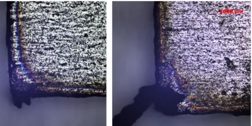
3.8 8 mm thickness laser cutting
Learning from a few previous cases, we can’t expect very smooth edges and nice, melt-free corners, as cutting an 8 mm stainless steel plate already pushes the boundaries of the laser machine. It works with higher gas pressure than before, both when inserting and cutting the contour.
Figure 4. End result condition with burned edges and surfaces with a lots of melted droplet using the 8 mm thickness stainless steel
The outer edges are relatively beautiful, but in the small cross-shaped cut out the corners are quite burr. It can be seen on the surface that due to the high pressure, the melt hits the part from below.
Applying less pressure would not blow the molten metal out of the cutting gap enough, and we would get an even worse result. We tried to improve the cut quality with speed and the usual parameters. With the set and accepted parameters, we could not achieve that no post-processing was required when cutting a plate of this thickness. However, since its application is quite rare, perhaps this is not such a problem in this case. However, it should also be borne in mind that cutting such thick stainless steel sheets at such a speed seemed unattainable a few years ago.
3.9 Comparison of the different thicknesses’ laser cutting
During the testing of the cutting parameters, different thicknesses were tested, with nozzles and pressures of different sizes prescribed for the plate thickness, these changed technological and raw material parameters had a clear effect on the cutting gap. A digital light microscope and the measuring system were used to geometrically characterize the cutting gaps, which results can be seen in Figure 5.
Figure 5. The effect of the sheet thickness on the width of the cutting gap
It was also predictable from the literature, but the tests show the tendency and extent of the change in the cutting gap, which increased monotonically due to the decrease in speed, nozzle diameter, and increase in plate thickness.
It can be seen what cutting qualities the 4,000 W ytterbium beam laser machine with nozzles of a given diameter and a given focus setting can achieve at different speeds and corner settings.
Cutting stainless steels is never easy, as in this case our cutting gas only helps to blow out the melt, the cutting of the plate is done by the laser. So achieving the highest possible performance and gas pressures when cutting this material with a laser is essential. The cutting power and gas pressure of 4,000 W and almost 20 bar was able to achieve the cutting quality better.
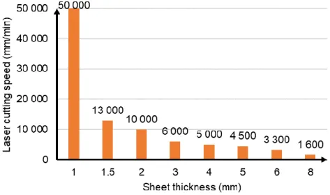
It can be seen that as the plate thickness increased, the cutting speed decreased at a rapid rate. This process is illustrated in Figure 6.
Figure 6. Evolution of laser cutting speed as a function of plate thickness
For all fiber lasers, can be seen that cutting sheets thinner than 1 mm is very easy and can achieve high speeds in addition to being able to blow through in the right quality. However, when cutting plates thicker than this, since the cutting gas pressure cannot be increased by the ratio of the thickness, our speed drops greatly.
In this experiment, we focused on the aesthetic requirements of the cut edge, its fine surface quality, however, if we had focused on the speed and accepted it, we would be satisfied with the minimally burr edges, we would get different parameter values. Overall, the default settings were not the best and managed to improve the quality of the cut edge, however, there are plenty of unknown factors for laser cutting and it is conceivable that similarly good solutions could have been found with other focus values.
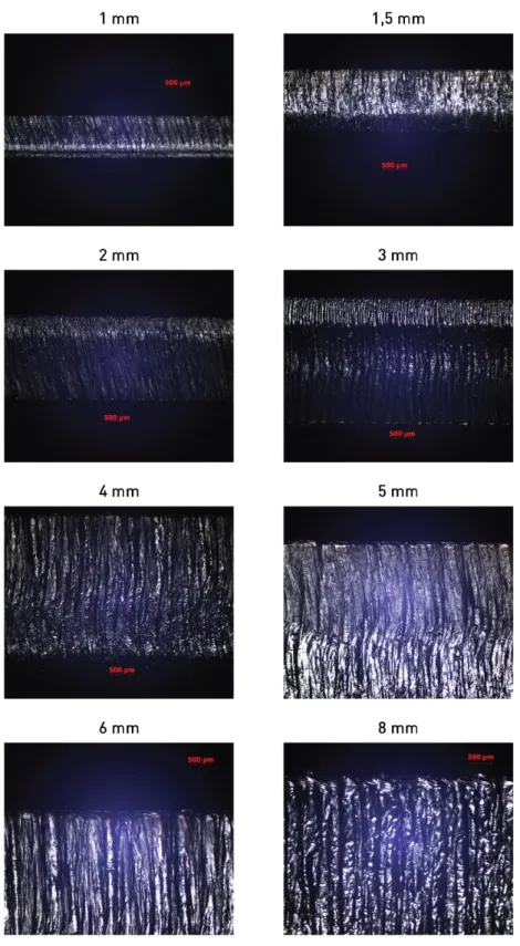
The quality of the cut edges was examined by microscopic images, which are shown in Figure 7.
Figure 7. The condition of cutting edge with the optimized parameters
4 Summary
In a series of experiments with laser cutting technology, we performed cutting tests on stainless steels of different thicknesses. In the process, we created a test geometry that we aimed to optimize for each plate thickness, where the goal of optimization was to improve the quality of the cut surfaces.
This was achieved by changing the parameters of the laser beam technology, where the time, gas pressure, frequency, power of the paragraph were changed, and then these parameters were also changed during the straight line travel of the laser optics and the reversal of arcs / corners. By
repeating the different cutting tests, we aimed to fine-tune the parameters and evaluate the quality of the surfaces thus created by microscopic examinations. The aim of the study was to improve the quality and productivity of the cutting of stainless materials used in mass production. The aim of the study was successfully achieved, the cutting conditions of 1, 1.5, 2, 3, 4, 5, 6 and 8 mm thick plates were examined and the acceptable cut surface quality up to 6 mm plate was accepted without post- processing. Cutting the 8 mm thick plate was a limitation of the laser system, so it failed.
We have successfully identified the appropriate parameter uses, thus facilitating the work of technicians and engineers to respond quickly to industrial needs. Our goal is to repeat this cutting pattern template on other laser equipment and with different optics and nozzles.
Acknowledgment
This research is supported by EFOP-3.6.1-16-2016-00006 "The development and enhancement of the research potential at John von Neumann University" project. The Project is supported by the Hungarian Government and co-financed by the European Social Fund.
References
[1] Cui, X. Wang, S. Wang, S. : A method for optimal design of automotive body assembly using multi-material construction, Materials and Design, 2008, pp. 381–387, DOI:10.1016/j.matdes.2007.01.024
[2] Ficzere, P. Laszlo Lukacs, N. Borbas, L.: The Investigation of Interlaminar Failures Caused by Production Parameters in Case of Additive Manufactured Polymers, Polymers, 2021, 13, pp. 556,
DOI:10.3390/polym13040556
[3] Molnár, L. Csiszér, T. Borbás, L.: Optimization of laser beam cutting parameters of high density composite fibre cement flat board, In: Pastrama, Stefan Dan; Constantinescu, Dan Mihai, 35th Danubia Adria Symposium on Advances in Experimental Mechanics, Sinaia, Románia : Editura Printech 2018, pp. 133-134
[4] Seong, Y.O. Jae, S.S. Taek, S.K. Hyunmin, P. Lim, L. Chin-Man, C. Jonghwan, L.: Effect of nozzle types on the laser cutting performance for 60-mm-thick stainless steel, Optics & Laser Technology, 2019, Volume 119, pp.
105607, DOI:10.1016/j.optlastec.2019.105607
[5] Svéda, M. Kálazi, Z. Buza, G. Roósz, A.: Lézersugaras felületkezeléssel létrehozott monotektikus felületi rétegek geometriai jellemzői, BKL Kohászat, 2009, 142, pp. 33-37, real-j.mtak.hu/13478/
[6] Csizmadia, T. Hopp, B. Smausz, T. Bengery, Z. Kopniczky, J. Hanyecz, I. Szabó, G.: Fabrication of SERS active surface on polyimide sample by excimer laser irradiation, Advances in Materials Sceince and
Engineering, 2014, pp. 987286 DOI: 10.1155/2014/987286
[7] Buza, G.: Funkcionális felületek létrehozása lézersugárral, Acta Periodica (Edutus), 2017, 13, pp. 15-22, ISSN 2063-501XIII
[8] Meszlényi, Gy. Bitay, E.: Az egyimpulzusos lézersugaras fúrás folyamatának elemzése, BKL, Kohászat, 2018, Vol 151, pp. 40-44, ISSN 0005-5670 •
[9] Maloveczky, A. Windisch, M. Szabó, D. Buza, G. Ugi, D.: Mikrooszlopok előfaragása szilicium egykristály mintán femtoszekundomos lézer segítségével, Anyagvizsgálók Lapja, 2020, Vol 1, pp. 25-27
[10] Bán, K. Nagy, M. Fogarass, Zs. Szabó, A.: Comparison of direct and indirect structural analysis of HAZ after laser cutting in amorphous alloys, Acta Physica Polonica A, 2020, Vol 137, pp. 861-863,
DOI:10.12693/APhysPolA.137.861
[11] Szabó, A. Nagy, A. Kozsely, G.: Laser cutting technology development for Fe based metallic glass, In: Szakál, Anikó, IEEE 17th International Symposium on Intelligent Systems and Informatics Proceedings, Sisy 2019, Szabadka, Szerbia : IEEE Hungary Section, 2019, Vol 273, pp. 249-254, DOI:10.1109/SISY47553.2019.9111604 [12] Kőházi-Kis, A.: Temperature increase in a laser-beam heat-treatment of metals, GRADUS, 2019, Vol 6, pp. 159-
166, ISSN 2064-8014
[13] Al-Azzawi, A. Baumli, P.: Coating of 1.4404 stainless steel by a combination of brazing and nitriding, Metallurgical &
Materials Engineering Association of Metallurgical Engineers of Serbia, 2018, Vol 24, pp. 209-218, DOI:10.30544/391
[14] Péter, L. ; Sánta, O. Koós, G. Földi, J. Verő, B. Bátonyi, J. Schwarczenbarth, P. Mach, K. Kardos, I. Gyerák, G.G.:
Study of the Acid Pickling of Low-Alloyed Steels by Using a Descaling Workstation Simulating the Production Line, Steel Research International, 2015, Vol 86, pp. 704-715, DOI:10.1002/srin.201400564
[15] Jae, S.S. Seong, Y.O. Seungkyu, P.H.P. Taek-Soo, K. Lim, L. Yonghee, K. Jonghwan, L.: Underwater laser cutting of stainless steel up to 100 mm thick for dismantling application in nuclear power plants, Annals of Nuclear Energy, 2020, Vol 147, pp. 107655, DOI:10.1016/j.anucene.2020.107655