Fabrication and Characterization of Implantable Polymer Microinterfaces
Thesis
Anita Zátonyi
Supervisor: Zoltán Fekete, PhD
University of Pannonia F ACULTY OF E NGINEERING
Doctoral School of Chemical Engineering and Material Sciences
2020
DOI:10.18136/PE.2020.746
Pannon Egyetem, Vegyészmérnöki- és Anyagtudományok Doktori Iskola Működési Szabályzat
Idegszövetbe implantálható, polimer alapú mikroelektród-hálózatok kialakítása és vizsgálata Az értekezés doktori (PhD) fokozat elnyerése érdekében készült a Pannon Egyetem, Vegyészmérnöki- és
Anyagtudományok Doktori Iskolája keretében Vegyészmérnöki- és anyagtudományok tudományágban
Írta: Zátonyi Anita Témavezető: Dr. Fekete Zoltán
Elfogadásra javaslom (igen / nem) ……….
(témavezető)
A jelölt a doktori szigorlaton ... %-ot ért el,
Veszprém, ……….
(a Szigorlati Bizottság elnöke)
Az értekezést bírálóként elfogadásra javaslom:
Bíráló neve: …... …... igen / nem ……….
(bíráló)
Bíráló neve: …... …... igen / nem ……….
(bíráló) A jelölt az értekezés nyilvános vitáján …...%-ot ért el.
Veszprém, ……….
(a Bíráló Bizottság elnöke)
A doktori (PhD) oklevél minősítése…...
Veszprém, ……….
(az EDHT elnöke)
Pannon Egyetem, Vegyészmérnöki- és Anyagtudományok Doktori Iskola Működési Szabályzat
Fabrication and Characterization of Implantable Polymer Microinterfaces
Thesis for obtaining a PhD degree in the Doktoral School of Chemical Engineering and Material Sciences of the University of Pannonia
in the branch name of Chemical Engineering and Material Sciences Written by: Anita Zátonyi
Supervisor: Zoltán Fekete, PhD
propose acceptance (yes / no) ……….
(Supervisor)
The PhD-candidate has achieved ... % in the comprehensive exam,
Veszprém, ……….
(Chairman of the Examination Committee)
As reviewer, I propose acceptance of the thesis:
Name of Reviewer: …... …... yes / no ……….
(Reviewer) Name of Reviewer: …... …... yes / no ……….
(Reviewer) The PhD-candidate has achieved …...% at the public discussion.
Veszprém, ……….
(Chairman of the Committee) The grade of the PhD Diploma …... (…….. %)
Veszprém, ……….
(Chairman of UDHC)
Abstract
Fabrication and Characterization of Implantable Polymer Microinterfaces
Implantable neural prosthetics devices offer, nowadays, a promising tool in the therapy of neurodegenerative diseases and psychiatric disorders, which are non – responsive to drug treatments and it provides an effective opportunity for the restoration of lost motor functions.
The problem with state – of – the – art invasive intracortical probes is that they are fragile. Long – term reliability of these devices is questionable and still fail within months or even weeks. Lack of chronic reliability, mainly related to the foreign body reaction, is induced, at the beginning, by insertion trauma, and then exacerbated as a result of mechanical mismatch between the implanted device and the neural tissue. All these adverse inflammatory factors lead to the encapsulation of the implanted devices by astrocyte cells, and form a region depleted in neurons in the vicinity of the implant. In this PhD thesis, we have addressed this issue by showing a simple process to use a thiol – ene / acrylate softening polymer as a substrate material that changes its elastic modulus, under physiological conditions. The resulting structures are more compliant with the brain tissue thus mitigating the neuroinflammatory response during brain motions.
A well – known neural interface is the electroencephalography (EEG) that is a non – invasive technique, however high frequency signals are deteriorated due to the filtering property of the skull, and the scalp.
In this PhD thesis, we have addressed this issue by demonstrating an invasive method to record electrical activity from the cortical surface of the brain by micro – electrocorticography (ECoG). The use of high density micrometer electrodes with a diameter ranging from 15 to 20 μm, provides more localized recordings, but as the recording sites’ diameter decreases the impedance increases affecting quality of the recordings. In the present thesis a platinum black with high specific surface area was electrodeposited and has been used to improve the recording characteristics of small electrodes.
Multimodal recording schemes have been discovered to reveal the anatomical and functional connectivity of neuronal ensembles. In this PhD thesis two approaches were applied for the fabrication of flexible and transparent ECoG interfaces for multimodal purposes.
Összefoglaló
Idegszövetbe implantálható, polimer alapú mikroelektród- hálózatok kialakítása és vizsgálata
A neurális implantátumok részt vesznek számos neurodegeneratív betegségek és a pszichiátriai rendellenességek kezelésében, amelyek esetében gyógyszeres terápiával nem érik el a kívánt hatást. Agy – gép interfészek alkotóelemeként, gerincvelői idegi sérülések tüneti kezelését tudják biztosítani.
Az utóbbi évtizedekben, nem humán kísérletekre fejlesztett eszközök nagy része szilícium alapú, hátrányuk, hogy mechanikai tulajdonságaikban jelentősen eltérnek az agy szöveti állományától.
Élettartamuk, az érintett agyszövet implantációt követő gyulladásos reakciója miatt, erősen korlátozott.
Az idegentest reakció során, az implantátum körül hegszövet képződik, mely elektromos és térbeli szigetelőként viselkedik. Az eszközök élettartama szempontjából sokkal előnyösebb olyan anyagok választása, amelyek rugalmassági tulajdonságaiban jobban illeszkednek a szöveti környezethez. A doktori értekezésben tiolén/akrilát, hőre lágyuló polimerbőr készült implantátum kialakítását és a rajta végzett vizsgálatok eredményeit mutatom be. A polimer különlegessége, hogy fiziológiás körülmények között rugalmassági állandója egy nagyságrenddel csökken, így a heves immunreakció mértéke csökkenthető.
Az elektroencefalográfia (EEG) egy nem invazív, orvosi gyakorlatban alkalmazott módszer, jelentős hátrányai közé sorolhatjuk azonban, hogy a felvevő pontok igen nagy átmérővel rendelkeznek és azok is nagy távolságban helyezkednek el az idegsejtektől. A disszertációban olyan invazív, koponyacsont alá ültethető, polimer alapú implantátumok megvalósítását és tesztelését mutatom be, amelynél nem érvényesülnek az említett jelszűrő hatások. A dolgozat második felében kis geometriai átmérőjű (15-20
m) elektródokat alkalmaztam szelektív és nagy térbeli felbontású jelelvezetésre. Az impedancia csökkentése és a jelminőség javulása érdekében, nagy fajlagos felületű platina réteget választottam le, majd hosszú távú stabilitás vizsgálatokat végeztem a rétegen in vitro és in vivo körülmények között.
Az idegrendszer anatómiai és funkcionális kapcsolatának mélyebb megértése elengedhetetlen a terápiás módszereinek kialakításához, ezért kívánatos a multimodális megközelítés, ahol az elektrofiziológia és az optikai képalkotás előnyei ötvözhetőek. A dolgozat harmadik részében flexibilis és átlátszó ECoG eszközök kialakítására és tesztelésére összpontosítottam. Poliimid és indium-ón-oxid vezető réteg segítségével kialakított eszközt alkalmaztam sikeresen intrinszik optikai jel képalkotásra. Parylene HT és ITO vezető réteg segítségével kialakított eszközt alkalmaztam sikeresen egyidejűleg elektromos jelelvezetésre és két-foton mikroszkópiás képalkotásra.
Résumé
Fabrication et caractérisation de microélectrodes polymère implantables dans le tissu neuronal
Les prothèses neurales implantables offrent un outil prometteur dans la thérapie des maladies neurodégénératives et des troubles psychiatriques, qui ne répondent pas aux traitements médicamenteux.
Le problème avec les implantables intracorticales invasives qu'elles sont fragiles. La fiabilité à long terme de ces appareils est discutable. Le manque de fiabilité chronique, principalement lié à la réaction du corps étranger, est induit, au début, par un traumatisme d'insertion, puis exacerbé par suite d'un décalage mécanique entre le dispositif implanté et le tissu neural. Dans cette thèse de doctorat, nous avons abordé cette question en montrant un processus simple pour utiliser un polymère adoucissant thiolène / acrylate comme matériau de substrat qui modifie son module élastique, dans des conditions physiologiques. Les structures résultantes sont plus conformes au tissu cérébral, atténuant ainsi la réponse neuroinflammatoire lors des mouvements cérébraux.
Une interface neuronale bien connue est l'électroencéphalographie (EEG) qui est une technique non invasive, mais les signaux haute fréquence sont détériorés en raison de la propriété de filtrage du crâne et du cuir chevelu. Dans cette thèse de doctorat, nous avons abordé cette question en démontrant une méthode invasive pour enregistrer l'activité électrique de la surface corticale du cerveau par micro- électrocorticographie (ECoG). L'utilisation d'électrodes micrométriques à haute densité avec un diamètre allant de 15 à 20 μm, fournit des enregistrements plus localisés, mais à mesure que le diamètre des sites d'enregistrement diminue, l'impédance augmente, affectant la qualité des enregistrements. Dans la présente thèse, un platine avec une surface spécifique élevée a été électrodéposé et a été utilisé pour améliorer les caractéristiques d'enregistrement de petites électrodes.
Des schémas d'enregistrement multimodaux ont été découverts pour révéler la connectivité anatomique et fonctionnelle des ensembles neuronaux. Dans cette thèse de doctorat, deux approches ont été appliquées pour la fabrication d'interfaces ECoG flexibles et transparentes à des fins multimodales. Du polyimide avec ITO a été utilisé en imagerie optique intrinsèque, et du Parylene HT avec ITO a été utilisé dans des expériences d' imagerie à deux photons. Une fois le processus de fabrication terminé, notre étude s'est concentrée sur les performances et la stabilité de l'appareil
13
Table of Contents
Preface ... 16
1 GENERAL INTRODUCTION ... 18
1.1 Brain signals and neural recording ... 18
1.1.1 Neurons and neural circuit ... 18
1.1.2 Signal generation and propagation ... 18
1.2 Fundamentals of extracellular recordings ... 21
1.2.1 Local field potential (LFP) ... 21
1.2.2 Action potential (AP) ... 21
1.3 Requirements for recording electrodes ... 22
1.3.1 Methods of electrochemical characterization ... 23
1.3.2 Strategies for higher signal – to – noise ratio (SNR) ... 31
1.3.3 Methods of mechanical characterization ... 32
1.4 Materials for implantable devices ... 32
1.4.1 Neural recording interfaces ... 33
1.4.2 Neural tissue and intracortical electrode interfaces ... 39
2 SOFTENING POLYMER-BASED IMPLANTABLE MICROPROBES ... 41
2.1 Introduction ... 41
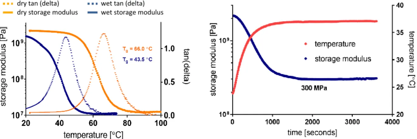
2.1.1 Synthesis and DMA characterization of thiol-ene/acrylate softening polymer ... 45
2.1.2 Cytotoxicity ... 46
2.2 Methods ... 46
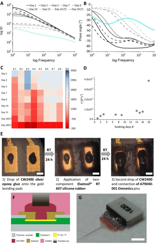
2.2.1 Design, microfabrication and elaboration of packaging ... 46
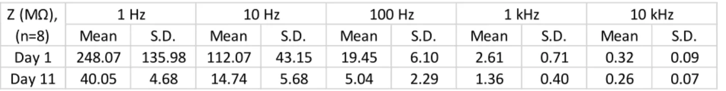
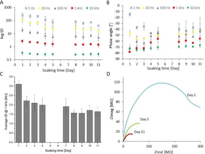
2.2.2 Electrochemical characterization ... 48
2.2.3 In vivo experiment ... 49
2.3 Results and discussion ... 51
2.3.1 Evolution of packaging ... 51
2.3.2 Electrochemical performance ... 53
2.3.3. In vivo of probe’s functionality ... 55
2.4 Conclusion and future concept ... 56
Thesis statement related to this chapter ... 57
14
Scientific paper related to this thesis statement ... 57
3 DURABILITY OF PLATINUM BLACK COATINGS ON NEURAL ELECTRODES ... 58
3.1 Introduction ... 58
3.2 Methods ... 59
3.2.1 Design, microfabrication and packaging ... 59
3.2.2 Electrochemical deposition and characterization ... 61
3.2.3 Cyclic Voltammetry measurements ... 63
3.2.4 Morphological investigations ... 63
3.2.5 In vivo experiments ... 64
3.3 Results and discussion ... 65
3.3.1 Electrochemical characterization ... 65
3.3.2 Stability assessment with mimicked in vivo conditions ... 73
3.3.3 Evaluation of electroactive surface area improvement with CV ... 74
3.3.4 Morphological investigations ... 76
3.3.5 In vivo SNR improvement ... 77
3.4 Conclusion and future concept ... 80
Thesis statement related to this chapter ... 81
Scientific paper related to this thesis statement ... 81
4 FLEXIBLE, TRANSPARENT ECoG DEVICES FOR MULTIMODAL NEUROIMAGING ... 82
4.1 Introduction ... 82
4.1.1 Targeted In vivo applications ... 83
4.2 Methods ... 85
4.2.1 Design, microfabrication and packaging ... 85
4.2.2 Optical characterization ... 87
4.2.3 Electrochemical characterization ... 88
4.2.4 Mechanical characterization ... 89
4.2.5 In vivo experiments on polyimide based ECoG in IOSI ... 93
4.3 Results and discussion ... 94
4.3.1 Optical evaluation ... 94
4.3.2 Electrochemical performance ... 95
4.3.3 Tolerance to cyclic bending loads ... 100
4.3.4 Performance of polyimide – based ECoG during in vivo experiments ... 104
15
4.3.5 Our results in comparison with other polymer materials for neural interfaces ... 106
4.4 Conclusion and future concept ... 107
Thesis statement related to this chapter ... 108
Scientific papers related to this thesis statement ... 108
5 BIBLIOGRAPHY ... 109
6 ACKNOWLEDGEMENT ... 128
7 LIST OF ACRONYMS ... 129
Appendix A – Microelectrode design for polyimide – based ECoG devices related to Chapter 3 ... 131
16
Preface
The microelectrodes act as an interface between the neural tissue and the artificial system. As microelectrodes have direct contact with biological tissue and are able to record extracellular biopotential signals or it can electrically stimulate neural tissue, they provide a powerful tool in the therapy of neurodegenerative diseases and psychiatric disorders (eg. Parkinson’s disease, essential tremor).
Substituting stiff, inorganic materials (eg. silicon) with soft, organic polymer materials (eg. polyimide) and combining their technology with standard microfabrication processes, allows the fabrication of considerably tiny and structurally diverse neurointerfaces.
The present thesis
The first Chapter, General Introduction, will present an overview of basic aspects related to the forthcoming chapters, starting from the understanding of the nervous system and the generation of neural electrical signals. As every neural interface presented in this thesis is for electrophysiological recording purposes, one part is dealing with the Requirements for Recording Electrodes and Materials for Implantable Devices. Substrate and conductive materials have been selected to best fulfill the requirements posed towards them, one part is giving an overview about Materials for Implantable Devices, pointing out the importance of the materials choice for the neuroimplantable devices.
The second Chapter is divided into three large groups (sub – Chapter), based on three different research objectives. At the beginning of each sub – Chapter there will be a short Introduction related strictly to the specific topic, and at the end of each sub – Chapter there will be a Discussion and a Conclusion about the main results achieved along the course of the related topic.
Main goals of the dissertation:
1) The sub – Chapter of Softening Polymer – based Implantable Microprobes, will focus on intracortical neural probes made of thiol – ene / acrylate softening polymer that change their elastic modulus under physiological conditions. These are promising candidates to mitigate neuroinflammatory response due to the reduced mechanical mismatch between the artificial interface and the brain tissue.
Reliability of brand new packaging technology is presented. Electrochemical stability of the proposed material composition is demonstrated and its recording performance in the hippocampus of rats is investigated.
17 2) The sub – Chapter of Durability of Platinum Black Coatings on Neural Electrodes, will focus on the investigation of electrodeposited platinum black and its stability on flexible neural interfaces (intracranial EEG and softening polymer – based microprobes). The attainable impedance improvement due to specific surface area enhancement is demonstrated. As a consequence of lower impedance values, higher signal – to – noise ratio (SNR) and consequently better electrophysiological signal quality are achievable when recording neural activity. Microelectromechanical System (MEMS) processes and protocols in details are presented, in contribution to electroplated implants without crack formation of the platinum black surfaces.
3) The sub – Chapter of Flexible, Transparent ECoG Devices for Multimodal Neuroimaging, will focus on flexible and transparent intracranial EEG devices that can be used in combined optical – electrical measurements. The importance of material choice from the perspective of its application will be identified.
Electrochemical and mechanical stability and optical characterization of the proposed material combinations will be evaluated.
18
CHAPTER 1
1 GENERAL INTRODUCTION
1.1 Brain signals and neural recording
1.1.1 Neurons and neural circuit
There are two main types of cells in the nervous system, neurons and glial cells. Neurons are cells that are specialized to transmit information through both electrical and chemical routes. Glial cells include oligodendrocytes, astrocytes and Schwann cells. Glial cells perform important functions in the brain, including providing structure and creating myelin sheath that speeds up action potential conduction velocity. Schwann cells provide the myelin in the periphery, while oligodendrocyte cells provide the myelin sheath in the central nervous system. Astrocytes help to set up the blood brain barrier. Glial cells can also regulate the response of synapses and neurotransmitters to injury, and likely perform many other vital functions. Our neural system is composed of nearly 100 billon cells, called neurons. Neurons come in many complex shapes, but generally they have a dendritic arbor, a cell body called soma and an axon. The soma is the metabolic center of the cell and the main site of protein synthesis. Dendrites receive information from other cells, inform the postsynaptic area for many incoming synapses. Dendrites often contain dendritic spines, which increase the surface area for synaptic connections. Each dendritic spine only receives information from one axon [1]. Figure 1. (a) shows a schematic of two connected neurons with their most relevant components. In the inset of Figure 1. (a), represents communication channel between two neurons, the so – called synapse. Electrical signals are translated into chemical signals first, then the
‘information’ can pass through the synaptic gap and reaches the other neuron, where the signal becomes electrical again.
1.1.2 Signal generation and propagation
A neuron is typically stimulated at dendrites and the signals spread through the soma. In resting state, there is a constant concentration difference of positively and negatively charged ions across the cell membrane. These concentration gradients are maintained by the sodium – potassium pump, which constantly brings potassium in and pumps sodium out of the cell. A permanent flow of ions is still maintained, but the net ionic transfer is zero, resulting in a constant transmembrane potential around
19 -70 mV (resting state potential). Excitatory signals at dendrites open ligand – gated sodium channels, and allow sodium to flow into the cell. This mechanism neutralizes some of the negative charges, and makes the membrane voltage less negative. It is known as depolarization, since the cell membrane becomes less polarized. The sodium diffuses inside the cell, and produces a current that travels toward the axon hillock.
If the summation of all input signals is excitatory and is strong enough, when it reaches the axon hillock, an action potential is generated. The axon hillock is also known as the cell’s “trigger zone”, since action potentials usually start here after being produced by voltage – gated ion channels that are mostly concentrated at the axon hillock. Voltage – gated ion channels form paths for ions to flow in and out of the cell, and as their name suggests, are regulated by membrane voltage. At threshold, sodium – channels open quickly followed by the opening of potassium channels somewhat later. As sodium ions rush into the cell, the intracellular charge distribution becomes more positive and this further depolarizes the cell membrane. The increase in voltage in turn causes even more sodium channels to open. This positive feedback continues until all the sodium channels are open and corresponds to the rising phase of the action potential. Note that the polarity across the cell membrane is now reversed. As the action potential approaches its peak, sodium channels begin to close. By this time, the slow potassium channels are fully open. Potassium ions rush out of the cell, and the membrane voltage quickly returns to its original resting value. This corresponds to the falling phase of the action potential. Note that sodium and potassium have now switched places across the membrane. As the potassium gates are also slow to close, potassium continues to leave the cell a little longer resulting in a negative overshoot called hyperpolarization. The resting membrane potential is then slowly restored thanks to diffusion and the sodium – potassium pump [2]–[7]. Representation of action potential generation and propagation along axon can be seen in Figure 1. (b & c). Action potential travels down the axon to the nerve terminal (pre – synaptic boutons).
From pre – synaptic boutons, vesicles of neurotransmitters are released and the neurotransmitter can act on the post – synaptic cell.
For an action potential to be generated, the signal must be strong enough to raise the membrane potential above a threshold, typically about -55 mV. This voltage level is the minimum required to open voltage – gated ion channels, and triggers a chain reaction that causes an action potential to fire and a neuron to relay messages to its own downstream synapses. Action potentials produce an electric field that is spreading from the neuron, and can be detected by placing electrodes nearby, allowing recording information represented by a neuron.
20 Figure 1. (a) Schematic drawing of two connected neurons, showing main structural components: axon, dendrites, synapses etc. Inset shows the communication at chemical synapses that requires the release of neurotransmitters [7]. (b) Mechanism of action potential generation and propagation along the axon [32]. (c) Time-dependent changes in membrane potential of an action potential: 1) stimulus applied, @ -55 mV the threshold reached and Na+ channels start to open, 1) – 2) depolarization: Na+ diffuses into the axon, the axon is more positive inside 2) - 3) @ peak Na+ channels begin to close and K+ channels are fully open, 4) repolarization: change from positive to negative inside, when K+ diffuses out of the neuron, 5) refractory period or hyperpolarization, where the impulse cannot go back in the same direction, 6) slowly restore and return to resting state [6].
21 1.2 Fundamentals of extracellular recordings
Cerebrospinal fluid (CSF) can be approximated as an ohmic, homogenous, frequency – independent and isotropic conductor medium. With respect to the cell membrane, which has high impedance, it has a high conductivity of 1.79 S/m at body temperature (37 °C) [8]. Neural tissue can be described as an ohmic conductor medium with inhomogenity and anisotropy. Neurons generate electric field, which can be measured with a sensor placing in the vicinity of signal sources. The measurable potential of volume conduction is inversely proportional to tissue conductivity and the generated electric field degenerates quickly with distance from the neural origin [9]. The challenge of recording network activity lies in the fact that each neuron communicates hundreds or thousands of others, and interrogation of all input and output signals is physically impossible. Extracellular signals are composed of local field potentials (LFPs) with a range of frequency from a few Hz to hundreds of Hz (~1 – 300 Hz), and action potentials (APs), which are detected at higher frequencies (few kHz) and often referred to as multi – or single unit activity (SUA) or briefly “spikes”. Amplitude of extracellular potential recorded from neurons is in the range of tens of microvolts [10].
1.2.1 Local field potential (LFP)
LFP is generated by synchronized low frequency summed inhibitory and excitatory postsynaptic potentials, and not only represents the superposition of action potentials, but holds information on slow glial potentials, calcium spikes after hyperpolarization phase following the action potentials [11], [12].
Recording LFP has the advantage that it characterizes population effects such as neural oscillations.
Similarly to electroencephalography (EEG) recordings, electrocorticography (ECoG) mainly sample electrical activity from pyramidal cells of the cortical layers 3 and 5. ECoG recordings are composed of LFPs and in very rare cases APs as well [13].
1.2.2 Action potential (AP)
If the neural cell membrane depolarization reaches the threshold level at the axon hillock, the neuron fires and an AP is generated and propagated in its axon. Nerve cell APs have a much smaller potential field distribution than LFPs and their duration is in the range of 1 – 2 milliseconds, consequently their contribution to intracranial EEG or ECoG signals is not remarkable. Because of the electrical properties of the brain tissue, the action potentials of neurons do not spread to large distance in the extracellular space.
The closer the active nerve cells are to the electrode sites, the greater the amplitude of the detected APs.
Electrode sites with appropriately small recording area should be placed no greater than 50 – 60 m far
22 from the neurons when the aim is to record single unit activity (or AP) and no greater than 100 – 150 m far from electrical signal sources considering multi unit activity recordings. The amplitude and shape of the recorded spikes increases the information content of extracellular recordings by displaying the function of different active neuron types. The spiking activity of a representative fraction of the neuron population in a small volume can be monitored with a sufficiently large density of recording sites.
1.3 Requirements for recording electrodes
The role of neural recording electrodes is to measure biopotential signals, spreading in the extracellular medium in form of ionic current, and transduce them to electrical signals. This conversion involving capacitive coupling (charging and discharging of the double layer) and faradaic reactions, when molecules of the electrode material and ions in the physiologic environment exchange electrons in a redox reaction [14], [15].
The mature technology behind neuroimplantable devices makes them now promising candidates for chronic implantation even in the human brain. Several factors that are enclosed in standards, developed by international organizations as FDA (U.S. Food and Drug Administration), ISO (International Organization for Standardization), ASTM (American Society for Testing and Materials), ANSI (American National Standards Institute) have to be considered for materials characterization to reduce the potential for adverse biological effects. Among ISO ad ASTM standards, one group is predominantly relevant in the characterization of neural electrodes: ISO 10993 that is Biological evaluation of medical devices and ASTM F1980-16, which is Standard Guide for Accelerated Aging of Sterile Barrier Systems for Medical Devices.
Based on international standards, neuroimplantable device materials are frequently tested in harsher – than – physiological conditions in vitro to assess preclinical data to demonstrate device reliability and effectiveness. Accelerated aging test method is an effective way to simulate the degradation mechanism of electrode material and determine degradation rate without longer time consumption. Our approach involves accelerated aging system, where elevated temperature was used and maintained during the whole period of experiment linked with daily impedance measurements to monitor changes in electrochemical and insulating performance of the proposed materials [16]. Rates of chemical reactions increase exponentially with increasing temperature. Based on a mathematical expression of the empirical observation, increasing the temperature by about 10 °C, roughly doubles the rate of many polymer reactions [17]. This empirical observation can be described as:
23 𝑡𝑠𝑖𝑚 = 𝑡𝑒𝑥𝑝∙ 𝑄10𝛥𝑇 10⁄ (1)
∆𝑇 = 𝑇𝑒𝑥𝑝− 𝑇𝑟𝑒𝑓 (2) 𝑡𝑠𝑖𝑚= 𝑆𝑖𝑚𝑢𝑙𝑎𝑡𝑒𝑑 𝑡𝑖𝑚𝑒 (𝑑𝑎𝑦𝑠)
𝑡𝑒𝑥𝑝= 𝐸𝑥𝑝𝑒𝑟𝑖𝑚𝑒𝑛𝑡𝑎𝑙 𝑡𝑖𝑚𝑒 (𝑑𝑎𝑦𝑠)
𝑄10= 𝐴𝑔𝑖𝑛𝑔 𝑓𝑎𝑐𝑡𝑜𝑟 𝑓𝑜𝑟 10 °𝐶 𝑖𝑛𝑐𝑟𝑒𝑎𝑠𝑒 𝑖𝑛 𝑇 𝑇𝑟𝑒𝑓 = 𝐵𝑜𝑑𝑦 𝑡𝑒𝑚𝑝𝑒𝑟𝑎𝑡𝑢𝑟𝑒 = 37 °𝐶
The aging factor (Q10) equals two for polymer materials [18].
1.3.1 Methods of electrochemical characterization
Common techniques for electrochemical characterization of neural microelectrodes are electrochemical impedance spectroscopy (EIS) and cyclic voltammetry (CV). These techniques can be applied, when the recording of local field potentials or the acquisition of single and multiple unit activity are aimed. In spite of DC methods, EIS with its AC wave stimuli has the advantage of slightly moving the cell away from its steady state, therefore the expected ion and solvent transport from the electrolyte to the conductive film and consequently the morphological and electrochemical transformation of the film is not significant. In previous Chapters the phrase of cell refered to the microscopic living organism, from this Chapter the phrase of cell will refer to electrochemical cell the assembly where electrochemical measurement takes place, consists of electrodes, electrolyte and the potentiostat.
Electrochemical Impedance Spectroscopy (EIS)
When our system reaches the equilibrium and forms the open circuit potential, no net current flows and only thermodynamic information is available. The potentiostat allows to drive the cell away from the equilibrium potential, and thus electrochemical reaction occurs. In Electrochemical Impedance Spectroscopy (EIS) small (amplitudes < 500 V), sinusoidal alternating current or potential of changing frequency is applied. An AC wave is defined by its frequency and amplitude. In EIS experiments, fixed amplitude and changing frequency is typically used. The frequency-dependence of different electrochemical processes allows to separate the contributions to the total response. Similarly to Ohm’s law, which defines the ratio of voltage and current as the resistance, in AC methods resistance is replaced with a more generic term, impedance. Impedance can be resistance, capacitance, inductance and diffusion as well, but it still defines the relationship between voltage and current. For example, AC stimulus applied as the voltage, AC current measured as the response, and the ratio in amplitude of two waves determines
24 its impedance level or the magnitude of impedance. The other parameter used for the characterization of the system is the phase or phase angle, and it represents the offset between the two waves. The current either leads or lags the voltage, and the shift between them is referred as phase angle θ.
The measured impedance characterizes the interface at the working electrode and electrolyte or extracellular medium. Current flows between the working and counter electrode, while the potential difference between the working and the counter electrode is such that the working electrode potential is at a set value with respect to a reference point. Frequency range for EIS measurements is selected to cover the range of interest. In neuroscience, it scales from 1 Hz to 10 kHz, depending on the neurophysiological information of interest. For instance, local field potential signals, that are including information on slow synaptic potentials, range between 1 – 300 Hz, while single – and multiunit activity are typically resolved at higher frequencies from 300 Hz to 10 kHz [12]. Bode plots will be used for data representation and analysis, where the magnitude of impedance and phase angle are plotted as a function of frequency.
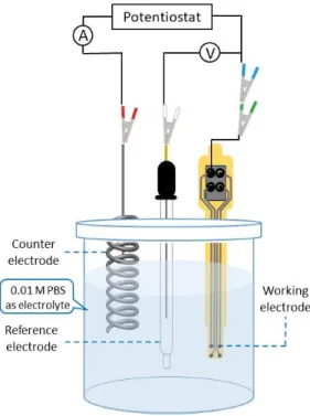
Information from high-frequency electrode kinetics, and from low-frequency diffusion or mass transport region can be obtained by analyzing Bode plots. Schematic drawing of a typical three compartment electrochemical cell that was used in EIS measurements can be seen in Figure 2.
Figure 2. Schematic drawing of three compartment electrochemical cell used in EIS measurements, platinum wire as counter, Ag/AgCl as reference and one recording site of our cortical microarray as working electrode respectively.
25 Equivalent circuit parameters at the electrode - electrolyte interface
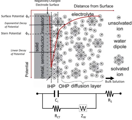
When an electrode is introduced to an electrolyte, it is initially electroneutral, however, chemical reactions immediately occur after. Due to these reactions, an electrical field develops that has an impact on the chemical reactions. When the competing reactions (oxidation – reduction) reach a steady-state, it is going to form an equilibrium, namely the open circuit potential. At this point currents still flow, electrochemical reactions still happen, but the net current is zero. According to the Gouy – Chapman model, the electric field also has an influence on the electrolyte, and an electrical double layer (DL) develops in the vicinity of the metal surface. The DL contains the Helmholtz planes (inner and outer) that contains ions adsorbed or electrostatically attracted to the surface and a diffuse layer. The charged metal surface attracts a layer of oriented water dipoles, which with the dehydrated (unsolved) ions adsorbed to the metal surface, defines the inner Helmholtz plane. Beyond this plane, a layer of hydrated ions is generated, closely attracted by the Coulomb force, known as outer Helmholtz plane (OHP). To sum it up, the electrochemical double layer exists, because the interface of a charged electrode in an ionic electrolyte forms a capacitor. The DL contains a less compact region that is the diffuse layer (or Gouy-Chapman layer) with mobile, solvated anions or cations distributed due to the contribution of the thermal forces and electrostatic interactions. Charge distribution of ions in a diffuse layer leads to an exponential drop of potential from the electrode surface to the bulk solution. The complete structure is electroneutral in a steady-state, since the net electric charge accumulated on the metal surfaces is balanced by the net electric charge in the diffuse layer. The theory that electrified electrode creates an interfacial charge distribution, developed by Helmholtz, resulted in the assumption that as an electrical circuit, the Helmholtz plane behaves like a parallel capacitor (linear potential drop across the Helmholtz plane), known as Helmholtz capacitance (CH):
𝐶𝐻=𝜀0𝜀𝑟𝐴
𝑑𝑂𝐻𝑃 (3) 𝐶𝐻 = 𝐻𝑒𝑙𝑚ℎ𝑜𝑙𝑡𝑧 𝑐𝑎𝑝𝑎𝑐𝑖𝑡𝑎𝑛𝑐𝑒 (𝑝𝐹)
𝜀0 = 𝐷𝑖𝑒𝑙𝑒𝑐𝑡𝑟𝑖𝑐 𝑐𝑜𝑛𝑠𝑡𝑎𝑛𝑡 𝑜𝑓 𝑣𝑎𝑐𝑢𝑢𝑚
𝜀𝑟 = 𝐷𝑖𝑒𝑙𝑒𝑐𝑡𝑟𝑖𝑐 𝑐𝑜𝑛𝑠𝑡𝑎𝑛𝑡 𝑜𝑓 𝑡ℎ𝑒 𝑒𝑙𝑒𝑐𝑡𝑟𝑜𝑙𝑦𝑡𝑒 𝐴 = 𝑆𝑢𝑟𝑓𝑎𝑐𝑒 𝑎𝑟𝑒𝑎 𝑜𝑓 𝑡ℎ𝑒 𝑒𝑙𝑒𝑐𝑡𝑟𝑜𝑑𝑒 (𝑛𝑚2)
𝑑𝑂𝐻𝑃= 𝐷𝑖𝑠𝑡𝑎𝑛𝑐𝑒 𝑓𝑟𝑜𝑚 𝑡ℎ𝑒 𝑂𝐻𝑃 𝑡𝑜 𝑡ℎ𝑒 𝑚𝑒𝑡𝑎𝑙 𝑒𝑙𝑒𝑐𝑡𝑟𝑜𝑑𝑒 (𝑛𝑚) = 0.2-0.5 nm (order of an ionic radius)
26 Considering the influence of thermal forces on the mobile ions in addition to the electric forces, a charge spread in an ionic cloud is formed near the interface. Distribution of diffused ions is taken into account with the Gouy – Chapman (diffusion) layer, where the potential drop is no longer linear, and with the Gouy – Chapman capacitance (CG):
𝐶𝐺=𝜀0𝜀𝑟
𝐿𝐷 𝑐𝑜𝑠ℎ (𝑧𝑉0
2𝑉𝑇) (4) 𝐶𝐺 = 𝐺𝑜𝑢𝑦 − 𝐶ℎ𝑎𝑝𝑚𝑎𝑛 𝑐𝑎𝑝𝑎𝑐𝑖𝑡𝑎𝑛𝑐𝑒 (𝑝𝐹)
𝐿𝐷= 𝐷𝑒𝑏𝑦𝑒 𝑙𝑒𝑛𝑔𝑡ℎ (𝑛𝑚) 𝑉0= 𝐴𝑝𝑝𝑙𝑖𝑒𝑑 𝑝𝑜𝑡𝑒𝑛𝑡𝑖𝑎𝑙 (𝑉) 𝑉𝑇 = 𝑇ℎ𝑒𝑟𝑚𝑎𝑙 𝑣𝑜𝑙𝑡𝑎𝑔𝑒 (𝑉)
𝑧 = 𝑁𝑢𝑚𝑏𝑒𝑟 𝑜𝑓 𝑒𝑙𝑒𝑐𝑡𝑟𝑜𝑛𝑠 𝑒𝑥𝑐ℎ𝑎𝑛𝑔𝑒𝑑 𝑖𝑛 𝑡ℎ𝑒 𝑟𝑒𝑑𝑜𝑥 𝑟𝑒𝑎𝑐𝑡𝑖𝑜𝑛
In the equation LD was used to represent the spatial decay of the potential:
𝐿𝐷= √𝜀0𝜀𝑟𝑉𝑇
2𝑛0𝑧2𝑞 (5)
𝑛0= 𝐶𝑜𝑛𝑐𝑒𝑛𝑡𝑟𝑎𝑡𝑖𝑜𝑛 𝑜𝑓 𝑖𝑜𝑛𝑠 𝑖𝑛 𝑡ℎ𝑒 𝑏𝑢𝑙𝑘 𝑠𝑜𝑙𝑢𝑡𝑖𝑜𝑛 (𝑖𝑜𝑛⁄𝑚3) 𝑞 = 𝐶ℎ𝑎𝑟𝑔𝑒 𝑜𝑓 𝑡ℎ𝑒 𝑖𝑜𝑛
The overall interface capacitance (CI) is the combination of CH in series with CG: 1
𝐶𝐼= 1 𝐶𝐻+ 1
𝐶𝐺 (6)
This ideal model is proposed for perfectly smooth electrode surfaces, however, the experimental conditions are never ideal. In order to model the imperfect or leaky capacitors due to the frequency dispersion, a new circuit element was introduced to substitute the interfacial capacitance, known as Constant Phase Element (CCPE). CPE is used as a replacement for the interfacial capacitance (CI) will always give a better fit to data, simply because offers one extra degree of freedom [19], therefore there is a single element fit with two different parameters. Impedance of a capacitor scales inversely with frequency, and this impedance of a CPE is expressed as:
𝑍𝐶𝑃𝐸(𝜔) = 1
𝑌(𝑖𝜔)𝛼 (7)
27 𝜔 = 𝐴𝑛𝑔𝑢𝑙𝑎𝑟 𝑓𝑟𝑒𝑞𝑢𝑒𝑛𝑐𝑦 (𝑟𝑎𝑑 𝑠𝑒𝑐⁄ ); 𝜔 = 2𝜋𝑓 (𝑓 = 𝑓𝑟𝑒𝑞𝑢𝑒𝑛𝑐𝑦 𝑖𝑛 𝐻𝑧)
𝑌 = 𝐶𝑜𝑒𝑓𝑓𝑖𝑐𝑖𝑒𝑛𝑡 𝑜𝑓 𝐶𝑃𝐸 (𝑆 ∗ 𝑠𝛼)(𝑓𝑟𝑒𝑞𝑢𝑒𝑛𝑐𝑦 − 𝑖𝑛𝑑𝑒𝑝𝑒𝑛𝑑𝑒𝑛𝑡 𝑝𝑎𝑟𝑎𝑚𝑒𝑡𝑒𝑟) 𝑖 = 𝐼𝑚𝑎𝑔𝑖𝑛𝑎𝑟𝑦 𝑢𝑛𝑖𝑡
𝛼 = 𝐶𝑜𝑛𝑠𝑡𝑎𝑛𝑡 (𝑓𝑟𝑒𝑞𝑢𝑒𝑛𝑐𝑦 − 𝑑𝑒𝑝𝑒𝑛𝑑𝑒𝑛𝑡 𝑝𝑎𝑟𝑎𝑚𝑒𝑡𝑒𝑟)
Constant α represents a ratio between capacitive and resistive behaviour of a non-ideal double layer formed on the surface of the conductive material, and it scales between 0 ≤ α ≤ 1. When α = 1, the equation describes the impedance of a pure capacitor, the coefficient Qα = C (the capacitance), and the measurable phase angle is -90°. For real surfaces with inhomogenities, the double-layer behaves like a CPE with α < 1.
For α = 0 CPE defines a pure resistance and for α = 0.5, it defines a Warburg element.
Figure 3. Schematic illustration of the electrode-electrolyte interface after the cell was driven away from its equilibrium (polarized). The inner Helmholtz or hydration layer contains ions adsorbed or electrostatically attracted to the surface, the outer Helmholtz layer contains hydrated (solvated) ions electrostatically attracted to the electrode’s surface as well. This double layer is followed by the diffuse layer contains mobile (solvated) ions. At the bottom equivalent circuit can be found with parameters as electrical representation of different interfacial layers.
Copied and modified from [285].
28 There are various theories that explain the physical correlation of α with surface roughness, charge uniformity, bulk properties of the coating or fluctuation of reaction rates along the electrode surface [20], [21]. The correlation between α and θ is given by
𝛼 =2𝜃
𝜋 (8) CCPE is proportional to the electrode surface area and the impedance goes with 1
𝐴𝜔
2𝜋
because of Equation 3.
Impedance of a given capacitor is higher when observing the lower frequency regions, and lower when at higher frequencies, therefore the interfacial capacitance (or CCPE) is the major contribution factor to the total response at lower frequencies. In order to describe the surface conditions in a more realistic way, another circuit parameter needs to be integrated in parallel to the capacitive elements, known as Charge-Transfer Resistance (RCT). RCT corresponds to faradaic reactions at the interface, lead to a net current flow across the electrode-electrolyte interface. Simplified equation of RCT for small signals is the following:
𝑅𝐶𝑇= 𝑅𝑇 𝑧𝐹𝐽0
= 𝑉𝑇 𝑧𝐽0
(9)
𝑅 = 𝑈𝑛𝑖𝑣𝑒𝑟𝑠𝑎𝑙 𝑔𝑎𝑠 𝑐𝑜𝑛𝑠𝑡𝑎𝑛𝑡 = 8.314 𝐽 𝑚𝑜𝑙𝐾⁄ 𝑇 = 𝐴𝑏𝑠𝑜𝑙𝑢𝑡𝑒 𝑡𝑒𝑚𝑝𝑒𝑟𝑎𝑡𝑢𝑟𝑒 (𝐾)
𝑧 = 𝑁𝑢𝑚𝑏𝑒𝑟 𝑜𝑓 𝑒𝑙𝑒𝑐𝑡𝑟𝑜𝑛𝑠 𝑒𝑥𝑐ℎ𝑎𝑛𝑔𝑒𝑑 𝑖𝑛 𝑡ℎ𝑒 𝑟𝑒𝑑𝑜𝑥 𝑟𝑒𝑎𝑐𝑡𝑖𝑜𝑛 𝐹 = 𝐹𝑎𝑟𝑎𝑑𝑎𝑦′𝑠 𝑐𝑜𝑛𝑠𝑡𝑎𝑛𝑡 = 96,485 (𝐶 𝑚𝑜𝑙⁄ )
𝑉𝑇 = 𝑇ℎ𝑒𝑟𝑚𝑎𝑙 𝑣𝑜𝑙𝑡𝑎𝑔𝑒 (𝑉)
𝐽0= 𝐸𝑥𝑐ℎ𝑎𝑛𝑔𝑒 𝑐𝑢𝑟𝑟𝑒𝑛𝑡 𝑑𝑒𝑛𝑠𝑖𝑡𝑦 (𝐴⁄𝑚2 )
Both CCPE and RCT are in the model to characterize the surface properties. I assume linear behaviour of the RCT when measuring impedance in vivo or in vitro, where the applied potential is zero or the potential is a small constant (eg. 25 mV) value, respectively. Besides the above described circuit parameters, further element, resistance of the solution or physiological environment, has to be taken into account. Spreading resistance (RS) is placed in series to the impedance of the interface. Equation 10. describes RS for circular electrode, which scales with 1
√𝐴𝑔𝑒𝑜 :
𝑅𝑆= 𝜌√𝜋 4√𝐴𝑔𝑒𝑜
(10)
29 𝜌 = 𝑅𝑒𝑠𝑖𝑠𝑡𝑖𝑣𝑖𝑡𝑦 𝑜𝑓 𝑡ℎ𝑒 𝑒𝑙𝑒𝑐𝑡𝑟𝑜𝑙𝑦𝑡𝑒 (𝑆)
𝐴𝑔𝑒𝑜= 𝐺𝑒𝑜𝑚𝑒𝑡𝑟𝑖𝑐 𝑠𝑢𝑟𝑓𝑎𝑐𝑒 𝑎𝑟𝑒𝑎 𝑜𝑓 𝑡ℎ𝑒 𝑒𝑙𝑒𝑐𝑡𝑟𝑜𝑑𝑒 (𝑛𝑚2)
RS generally describes the resistance of the bulk electrolyte combined with the internal, ohmic resistance of the metal contact sites and wiring of the working electrode. At high frequencies, ions are not able to follow the alternating electric field. Warburg element representing the frequency dependent impedance to ionic diffusion. Warburg impedance (ZW) is defined as:
𝑍𝑊= (1 − 𝑖) 𝜎
√𝜔 (11) 𝑖 = 𝐼𝑚𝑎𝑔𝑖𝑛𝑎𝑟𝑦 𝑢𝑛𝑖𝑡
𝜎 = 𝑊𝑎𝑟𝑏𝑢𝑟𝑔 𝑐𝑜𝑛𝑠𝑡𝑎𝑛𝑡 (Ω
⁄√𝑠𝑒𝑐) 𝜔 = 𝐴𝑛𝑔𝑢𝑙𝑎𝑟 𝑓𝑟𝑒𝑞𝑢𝑒𝑛𝑐𝑦 (𝑟𝑎𝑑 𝑠𝑒𝑐⁄ )
Although the effects of electrode impedance to the amplitude of extracellular recording and background noise is not thoroughly understood [22], we cannot ignore the effects of noise on the recorded waveforms. Most theories and experiments indicate that decreased impedance results in improved recording and stimulation capabilities [13], [23]–[26]. Thermal noise is thought to be the dominant noise source when performing cortical recording due to the high impedance of recording sites. Thermal noise arises from the thermal fluctuations of charge carriers within a conductor, and its root – mean – square (RMS) is proportional to the square root of resistive component of the impedance (marked as R in the equation). Thermal noise (Johnson – Nyquist noise, Johnson noise, or Nyquist noise) can be defined as:
𝑣𝑅𝑀𝑆= √4𝑘𝐵𝑇𝑅∆𝑓 (12)
𝑣𝑅𝑀𝑆 = 𝑅𝑜𝑜𝑡 − 𝑚𝑒𝑎𝑛 − 𝑠𝑞𝑢𝑎𝑟𝑒 𝑛𝑜𝑖𝑠𝑒 𝑣𝑜𝑙𝑡𝑎𝑔𝑒 (𝑉) 𝑘𝐵 = 𝐵𝑜𝑙𝑡𝑧𝑚𝑎𝑛𝑛 𝑐𝑜𝑛𝑠𝑡𝑎𝑛𝑡 = 1.38 ∙ 10−23 𝐽 𝐾⁄
𝑇 = 𝐴𝑏𝑠𝑜𝑙𝑢𝑡𝑒 𝑡𝑒𝑚𝑝𝑒𝑟𝑎𝑡𝑢𝑟𝑒 (𝐾)
𝑅 = 𝑅𝑒𝑠𝑖𝑠𝑡𝑖𝑣𝑒 𝑐𝑜𝑚𝑝𝑜𝑛𝑒𝑛𝑡 𝑜𝑓 𝑡ℎ𝑒 𝑖𝑚𝑝𝑒𝑑𝑎𝑛𝑐𝑒 𝑜𝑟 𝑅𝑒𝑠𝑖𝑠𝑡𝑎𝑛𝑐𝑒 (Ω)
∆𝑓 = 𝐵𝑎𝑛𝑑𝑤𝑖𝑑𝑡ℎ 𝑜𝑓 𝑓𝑟𝑒𝑞𝑢𝑒𝑛𝑐𝑦 (𝐻𝑧)
30 Schematic illustration and the inferred equivalent circuit parameters of the polarized electrode – electrolyte interface can be seen in Figure 3.
Cyclic voltammetry (CV)
Cyclic voltammetry is used for the characterization of the reactions on the electrode surface and for the assessment of stability on the deposited electroactive surface. It is also a powerful tool for reliable, homogenous electrochemical deposition of porous conductive films from its solution. Similarly to EIS, cyclic voltammetry measurements are carried out in three compartment electrochemical cells. The applied potential is cycled at a constant rate between two defined potential limits, while the current flows between the working electrode (in which the potential is applied with respect to a noncurrent-carrying reference electrode) and the counter electrode. The applied potential at the working electrode gives rise to electrochemical reactions eg. transport of charges through the test electrode – electrolyte surface, resulted in a measurable current. The position of measured current peaks gives quantitative information, while the area under current peaks provides qualitative information on the amount of charges transferred during the anodic (oxidation) or cathodic (reduction) reactions [27], [28].
Figure 4. Typical cyclic voltammogram of a porous platinum electrode. This figure was copied and modified from [286].
31 1.3.2 Strategies for higher signal – to – noise ratio (SNR)
Increasing the geometric surface area of the recording sites to reduce the impedance, would result in poor spatial localization of recorded action potentials from a neuronal ensemble. Geometric area improvement is also limited by the dimensions of microdevices. With smaller recording sites, it is possible to obtain higher spatial resolution by reducing the amount of spatial averaging of the LFP signals. For single-unit recording the microelectrode geometric surface area for penetrating probes should be maximum 2000 – 4000 m2 (d = 50 – 70 m) or much smaller [15]. As the site diameter decreases, the impedance increases. Higher impedance values contribute to lower signal – to – noise ratio (SNR), resulted in less sensitive recording where strong electrical noise components (eg. 50 Hz) suppress useful signals. In order to measure single-unit neural activity, the SNR should be above 5:1, and the impedance of recording electrodes should be between 50 kΩ to 1 MΩ at 1 kHz [15]. A trade-off has to be found between high spatial resolution (selectivity) and high SNR (sensitivity) of the recording. A feasibly strategy is the deposition of porous inorganic (eg. platinum black, [29]–[31]) or organic (eg. Poly(3,4- ethylenedioxythiophene) (PEDOT) [20], [32]–[37]) materials on sputtered, evaporated metal surfaces or on carbon nanotubes, nanowires. It is also an appropriate solution to nanostructure the conductive layer [38], [39]. This strategy enables small geometric surface area with increased electroactive area via the increased surface roughness of the electrode sites.
The electroactive surface area represents the surface area of an electroconductive material accessible for the electrolyte [40]. The deposited porous layer causes an extension in electroactive surface area. The improvement in effective surface area is characterized by the roughness factor. The roughness factor or the extent of inhomogenity, is determined by dividing the established effective surface area by the geometric surface area of an ideally flat, homogenous and polycrystalline metal electrode (standard value for platinum is 210 C/cm2 [41]). The amount of charges adsorbed on a rough surface, and consequently the electroactive surface area, is determined by analyzing the charge under the peaks of the hydrogen desorption area of cyclic voltammetric (CV) curves [42]. Both faradaic and non-faradaic currents scale linearly with the surface area, therefore improved effective surface area has an impact on equivalent circuit elements, namely the double-layer capacitance (non-faradaic) and charge-transfer resistance (faradaic). Electrical double-layer increases while resistance to charge-transfer decreases resulted in lower impedance values and consequently better SNR. A typical cyclic voltammogram of a porous platinum electrode can be seen in Figure 4.
32 To conclude this subsection, in order to obtain more localized sensing regions and better unit recording capabilities, small electrode sites of the lowest possible impedance values are needed. To lower the impedance, microscopic irregularities need to be introduced on the smooth surface of the microelectrodes for example with the electrodeposition of porous conductive materials.
1.3.3 Methods of mechanical characterization
The flexible micro – electrocorticography (ECoG) electrode arrays presented here are based on a polymer/(metal or metal – oxide)/polymer sandwich structure. Prior studies employed mostly tensile loads to evaluate the mechanical stability of the thin systems (all together few microns in thickness) [43]. To demonstrate the robustness of the proposed structures under bending loads and to identify unique failure mechanism if any occurs, an individual test procedure was developed, where integrity was measured by four wire resistance method. The repetitive deformation of these structures is simulated by cyclic bending loads. For these type of sandwiched structures, the bending stiffness is dominated by the conductive layer [44], which was placed at the neutral plane to enhance tolerance to bending loads [45]. The same strategy was applied with test structures and with ready – to – use devices.
1.4 Materials for implantable devices
In this Chapter, substrate and encapsulation materials for neural interfacing will be discussed. In many cases, these two layers are made of the same material composition. Substrate is the mechanical carrier for the electrical components. Substrate technology has a direct impact on achievable form factors, available assembly processes, and reliability and performance of the device. Rigid substrate technology are based on stiff materials eg. silicon (Si), glass, polyetheretherketone (PEEK) etc. Flexible substrate technology relies on flexible, mainly polymer films eg. polyimide (PI), liquid crystal polymer (LCP), poly(para – xylylene) (PPX), polydimethylsiloxane (PDMS), shape – memory polymers (SMP), nanocomposites (NCs) etc. Hybrid substrate technology offers the combination of rigid and flexible materials. In view of the rigorous clinical approval process, consideration of biological, mechanical, and material risk factors are challenging. Material for neural implants must fulfill general requirements:
• Biocompatibility
• Low toxic effect and attenuated long-term histological effects in the brain
• Flexibility (small Young’s modulus and large elongation)
• Mechanical durability (high tensile strength)
• Good electrical insulation
• Low moisture absorption and permeability
• Compatible with microfabrication techniques
33 Besides materials choices, the U.S. Food and Drug Administration (FDA) considers other factors in their decision in order to allow devices participating in human clinical trials eg. form factor, functionality, and implantation procedure. More detailed description on each applied polymer material will be given in the introduction of the related chapters.
1.4.1 Neural recording interfaces
Neural electrodes are interfacing the biological system to record signals generated in the active region of nervous system. They provide compact readouts of potential changes caused by the electrical activity of neural ensembles. These technology provide an important tool to better understand brain functions and organization of neural structures. The recording interfaces have also shown promise in treatment of neurological disorders and mental disabilities (for patients with intractable epilepsy for presurgical brain mapping and seizure foci localization [46], in the rehabilitation of lost motor functions [47]). Combination of the biological relevance of recording interfaces with recent advances in semiconductor fabrication process or microfabrication technology results in reliably small, densely packed microelectrode system with higher spatial resolution in the horizontal plane at the surface of the cerebral cortex [48], [49]. For long-term, chronic applications, electrode materials need to be improved to fulfill several requirements demanded during the interaction with living cells and organs. These requirements are (1) material (flexibility/rigidity, biocompatibility, molecular properties of building block, easily tunable chemical composition and mechanical properties) and design (shape, physical parameters) conformity to the neural tissues, (2) facile and reliable production with conventional microfabrication technologies, that uncomplicated the manufacturing of implantable devices with, (3) reliable recording over long period of time (foreign body response depends on leachable components from electrode materials, endotoxins, size, mechanical feature etc.), (4) the ability to simultaneously record potentials from various populations of neurons. Six different types of recording electrodes can be classified in the field of neural prosthesis regarding the targeted tissue and the location of electrodes:
1. Penetrating intracortical electrodes (microwires, cortical microelectrodes or shallow probes, depth electrodes)
2. Penetrating peripheral nerve electrodes (microwires, intrafascicular electrodes, microelectrode arrays, regenerative interfaces)
3. Non-penetrating cortical electrodes (planar or ECoG electrode arrays) 4. Non-penetrating peripheral nerve electrodes (cuff electrodes)
5. Endovascular probes or stentrodes 6. Neural dust
Summary of neuroimplantable devices and their position relative to brain layers can be seen in Figure 5.
34 Figure 5. Invasive (purple area) & non-invasive (blue area) neural recording interfaces and their location in reference to the brain (upper-left image), copied from [287]. Waveforms measured with different electrophysiological methods and their range of amplitude & frequency, copied and modified from [11] (upper-right image). The measured signal amplitudes for ECoG electrodes are larger compared to scalp EEG electrodes, and lower compared to penetrating electrodes. Main picture: Overview of neuroimplantable devices including FDA-approved devices, recent progress in academic field, and commercially available probes for nonhuman research purposes. Copied from [52].
35 Penetrating microelectrodes can be divided into two main groups. First one with metal core and a glass or polymer insulating layer, where the non – insulated metal contacts define the recording sites. The second one consists of silicon core and polymer or inorganic insulation while the tip of the semiconductor needles are covered with thin film of metal layer (eg. platinum). These three – dimensional electrode arrays are embodied by the Utah arrays. The other well – known example for silicon – based multielectrode arrays are known as Michigan arrays, where several recording sites are patterned along the length on each silicon shank. By using microfabrication and semiconductor technology, the issue of imprecise location and differences in physical parameters (shape, size) of recording sites has disappeared. Michigan and Utah electrode arrays were successfully applied to record from the cortex of animal subjects [50]–[52] however, they are prone to break easily, since their core material is brittle silicon having a Young’s modulus around 200 GPa. Moreover, because of the great mechanical mismatch at the interface of the array and the biological tissue, the implant causes strong immune response [53]–[57]. The localized tissue inflammation evolves as long as the array is present due to the continuous micromotion of the brain, resulted in a loss of signals at certain frequency ranges and degradation of neural recording reliability. Schematic representation of evolved foreign body immune response around stiff and compliant (flexible) probes can be seen in Figure 6. (a & b), from [57]. In order to address this issue and to maintain a stable recording over long period of time, more flexible materials were engineered as substrate and encapsulating layers, forming third major category among penetrating probes. These polymer materials have Young’s modulus in the few MPa or GPa range (Table 1.).
Table 1. Summary of the most relevant physicochemical properties of common neuroimplant materials (polymers:
PI – polyimide, Pary C – Parylene C, Pary HT – Parylene HT, LCP – liquid crystal polymer, PDMS – polydimethylsiloxane, SMP – shape memory polymer and Si - silicon as reference material).
36 Although these values are far (several magnitudes larger) from that of the biological tissue (EBrain = 3.15 – 10 kPa [57, 194],EPeripheral Nerves = 400 − 700 kPa [58], ENeuron = 0.1 – 8 kPa (depending on their position in the brain) [59]). Polyimide, Parylene, PDMS, Liquid Crystal Polymers, SU-8 etc. are more compliant with the soft neural tissue than their rigid counterparts (eg. silicon), elastic modulus of different natural and artificial materials are compared in Figure 6. (c). Nevertheless, polymer – based neuroimplants are also biocompatible and compatible with standard microfabrication processes. Standard biocompatible metals like platinum (Pt), indium – tin – oxide (ITO), titanium (Ti), iridium (Ir) and gold (Au) that were used with silicon for neural interfaces, can be combined with polymers to form the conductive layer for recording sites, contact pads and connecting traces. Penetrating electrodes with sub – micron diameter are less invasive than traditional silicon microelectrodes. With their physical dimensions, the extent of cell damage around the probe track is less severe, which implies that the neuroinflammatory response is less intense.
Figure 6. Schematic representation of neuroinflammatory response around stiff (a) and compliant (b) cortical implants, copied from [57]. (c) Mechanical scale representing the elastic (Young’s) modulus of natural materials related to brain Cell/tissue ensembles and artificial materials applied as substrate or coating materials for neural interfaces (PDMS – Polydimethylsiloxane, SMP – Shape Memory Polymer (thiol-ene/acrylete-based), PaC/HT – Parylene C/HT, PET - Polyethylene terephthalate, LCP – Liquid Crystal Polymer, Pt – Platinum, Si – Silicon, W – Tungsten).
37 This feature eventually allows more reliable long – term neural recordings. On the other hand, they are tend to bend and buckle easily during the implantation procedure that is an avoidable risk factor.
The problem with state – of – the – art intracortical devices is that they are fragile and they are still penetrating the brain (invasive). Clinical neurosurgeons are very reluctant to implant such devices into the human brain, because they can easily break. The answer to this challenge was the invention of a less invasive electrocorticography (ECoG) arrays. Neural multielectrode interfaces that are able to record neural activity from the cerebral cortex can be divided into two categories: electroencephalography (EEG), and intracranial EEG (iEEG) or electrocorticography or micro – electrocorticography (ECoG or ECoG).
Spatio – temporal resolution of different neural interfaces are illustrated on Figure 7., copied from [60].
EEG is a non – invasive technique, where multiple electrodes are placed on the external scalp of the experimental subject, and synchronized activity of large population of neurons is recorded. EEG electrodes are at remarkable distance from the neural cells. Due to the filtering property of skull, subcutaneous tissue Figure 7. Demonstration of the spatio-temporal resolution of current brain monitoring technologies (including electrophysiological and brain imaging-based methods). Copied from [60] (MEG - Magnetoencephalography, EEG - Electroencephalography, ECoG - Electrocorticography, fMRI - Functional Magnetic Resonance Imaging).
38 and the scalp, the signal is considerably smoothed. Information can only be acquired by applying electrodes with large contact area that means poor spatial resolution. High frequency signals are deteriorated by the skull and only low frequency components (below 60 – 80 Hz, depending on the thickness) can be captured [61]. It is notable that EEG has an excellent temporal resolution (millisecond range) among different non – invasive techniques.
Electrocorticography (ECoG) devices are placed directly onto the exposed surface of the brain, more precisely on the surface of the cerebral cortex, that is the thin, outer layer (1.5 – 5 mm) of the cerebrum [11]. ECoG can be implanted above or under the dura mater, mainly used for mapping of primary brain functions [52], discovering brain „connectome” and in human neurosurgery for the reliable localization of epileptogenic brain tissue during neurosurgery [62]–[67]. Implantation of these devices are less invasive in comparison to intracortical microelectrodes, as the brain tissue is not punctured and the evoked immune response to the artificial device is less intensive. Craniotomy is required to record signals that are composed of synchronized postsynaptic potentials [11]. By removing the skull, scalp and subcutaneous tissue, their filtering and signal attenuation effect is eliminated, creating a more information rich signals with higher spatial resolution than that of traditional EEG. When the aim is to fabricate epi– or subdural arrays that contain large number of electrodes with smaller electrode diameter, traditional techniques have proven to be very time consuming and the interelectrode spacing varied in space resulted in irregular recording patterns [68]. This irregularity complicates cortical mapping because of the spatially undefined electrode sites. With the evaluation of microfabrication processes, it has become possible to fabricate ECoG arrays assembled in a desired and predetermined way, that helps the data processing and in the localization of evoked potentials’ sources [52]. Microfabrication technologies have the advantage of constructing extracellular electrode arrays (ECoG) with very high density and with a diameter below 500
m (for human experiments) [68]. Due to the above mentioned precise location of densely packed, smaller recording sites with close proximity to neural cells, higher spatial resolution, better recording quality of high frequency activity and better SNR are available compared to EEG [69]. ECoGs are organic material – based, biocompatible devices with ultraconformable shaping possibilities (thickness of few micrometers is available), and hence the microtechnology, scalable design and fabrication is achievable with neuron – sized density (eg. 20 m diameter, 30 m interelectrode distance for rodents). However, the models used for data processing of EEG signals often fail when they applied for such small scales, ECoGs are still a promising candidates for the fabrication of brain – machine interfaces (BMIs) [70]–[72]. ECoG – based brain computer interfaces (BCIs) can participate in the treatment of neuromuscular disorders [73], [74] by
![Figure 4. Typical cyclic voltammogram of a porous platinum electrode. This figure was copied and modified from [286]](https://thumb-eu.123doks.com/thumbv2/9dokorg/877393.47221/30.918.127.793.595.918/figure-typical-cyclic-voltammogram-porous-platinum-electrode-modified.webp)

![Figure 6. Schematic representation of neuroinflammatory response around stiff (a) and compliant (b) cortical implants, copied from [57]](https://thumb-eu.123doks.com/thumbv2/9dokorg/877393.47221/36.918.201.708.453.933/figure-schematic-representation-neuroinflammatory-response-compliant-cortical-implants.webp)