An International Journal for Engineering and Information Sciences DOI: 10.1556/606.2020.15.3.5 Vol. 15, No. 3, pp. 49–59 (2020) www.akademiai.com
FOCUSING OF LIGHT PULSES BY DIFFERENT TYPES OF WAVY PARABOLIC MIRRORS
1 Gergely NYITRAY*, 2 Patrik ELTER
1 Department of Automation, Faculty of Engineering and Information Technology, University of Pécs, Boszorkány u. 2, H-7624 Pécs, Hungary, e-mail: nyitray@mik.pte.hu
2 Department of Electrical Networks, Faculty of Engineering and Information Technology University of Pécs, Boszorkány u. 2, H-7624 Pécs, Hungary, e-mail: elter@mik.pte.hu
Received 11 March 2020; accepted 9 September 2020
Abstract: The propagation of an ultra-short light pulse is studied in the framework of scalar diffraction theory. Light pulses are focused by different types of wavy parabolic surfaces. The temporal-spatial behavior of the two-dimensional wave field is computed in the vicinity of the focal plane. It is shown that the slightly perturbation from the perfect parabolic shape leads a space-time dispersion of the pulse in the neighborhood of the focus.
Keywords: Diffraction, Mirrors, Ultra-short light pulses
1. Introduction
Since the advent of the laser over sixty years ago, there has been intense interest in the quest to generate ultra-short laser pulses in the picosecond and femtosecond time scale. Nowadays great efforts have been devoted to generate and study pulses in the attosecond regime, based on highly nonlinear frequency conversion of femtosecond sources into the soft X-ray spectral region. As the period of one optical cycle in the near-infrared is just 2.7 femtoseconds, lasers with pulse widths in this range up to about 100 femtoseconds are generally termed, ‘ultra-fast’ lasers. As a pulse shorter than the period of the carrier frequency is basically a DC signal, optical pulses are now about as they are going to get. On the one hand a shorter optical pulse affords a higher time resolution in pump-probe measurements, allowing a wealth of physical processes to be studied as ultra-fast processes in chemical and biological materials, optical
* Corresponding Author
communications, medical imaging, ultra-fast time-resolved spectroscopy, and radio frequency signal processing. On the other hand a short optical pulse can produce extremely high peak powers with only moderate energies. A typical amplified Ti:Al2O2
ultra-fast laser system can produce 1 mJ pulses of 100 fs duration, which corresponds to roughly 10 GW of power. When these pulses are focused, it is simple to obtain intensities greater than 1015 W/cm2, where the electric field of the optical pulses is comparable to the binding field of electrons to ions. Many new nonlinear optical phenomena manifest themselves in this regime. The study of most nonlinear optical processes becomes routine, and even more exotic effects become accessible: high- harmonic generation, attosecond X-ray generation and relativistic nonlinear optics.
Over the past two decades, the propagation characteristics of ultra-short, and hence ultra-wide bandwidth pulses, including spectral changes, the distortion of the pulse time, shape etc. have been investigated. The temporal and spatial behavior of a focused short pulse was studied in [1]-[7]. The spatial profile of a femtosecond pulse front can suffer a considerable distortion upon propagation through a lens. The delay between the pulse and phase fronts is proportional to the difference between the group and phase velocity of the light in the material of the lens. It is also proportional to the path length of the ray in the material of the lens, therefore the delay is different for various regions of the lens cross section and it can be described by a parabolic function of the distance from the optical axis. According to the numerical calculations based on geometric optics the pulse front even may form a loop, which means that the marginal rays have already passed the focus, while axially propagating part has not reached it yet [2]. Calculations based on scalar diffraction theory supported the prediction of geometric optics and show that the intensity distribution in the focal plane is different from the Airy pattern. The diffraction pattern consists of rings, with continuously increasing radius. Perhaps, the most unexpected result of that investigation is that a spike appears on the optical axis in front of the horseshoe-shaped pulse front. The properties of the boundary wave pulse are studied in [2]. A direct explanation of the formation of the boundary wave pulse is given in [8].
The current work aims to visualize the light field in the focal plane given by the imperfect (wavy) parabolic mirror. The transverse intensity distribution of the focused pulse is controlled by the undulation of the mirror surface.
2. Focusing of continuous waves
The paraboloid mirror is an ideal focusing device. An optical instrument that collects the parallel incident light into a single focal point, within the accuracy of the Gaussian optics, is called an ideal focusing device. Paraboloid mirrors have neither chromatic nor spherical aberration, which is inevitably property of a common lens. The nearly full paraboloid capable of focusing within 4 solid angle as compared with lens that can focus light only within 2 solid angle. A rigorous diffraction theory of focused light from parabolic mirrors has been developed over the course of nearly a century, beginning with a treatment in 1920 by Ignatovsky [9]. Another theoretical approach was provided by Richards and Wolf [10], [11], where strongly focused beams were accurately described.
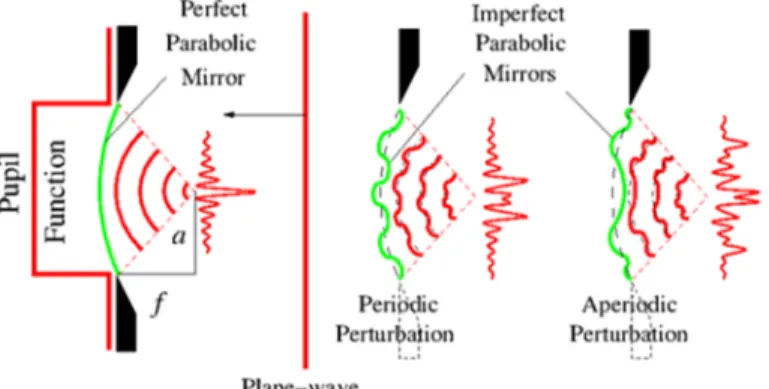
For further discussion about focusing and diffraction the reader may refer to books e.g. [12], [13]. The paraboloid and spherical mirrors as dispersion-less optical instruments play important role in the field of generation short pulses of a few optical cycles. As it is shown in Fig. 1, the mirror is assumed to lie in the ( , ) plane and the observation plane ( ′, ′) is shifted by from it.
Fig. 1. On the left: the perfect paraboloid mirror converts the monochromatic plane waves into spherical-like waves converging to the focal plane; on the right: the surface imperfection of the
mirror modifying the energy distribution
From a wave optical point of view a paraboloid mirror is curved surface which simply delays an incident wavefront by an amount proportional to the dependent variable of the paraboloid function at each point. Then the total phase delay suffered by the wave in reflecting back from the surface of the mirror may be written
2 , (1)
where 1, 2 / is the wavenumber, stands for wavelength and . The diameter of the mirror is 2 . The value of parameter is characterizes the paraboloid mirror shape.
The perfect paraboloid mirror converts the monochromatic plane waves into spherical-like waves having radius of curvature of converging to the focal point. If the mirror is unperturbed the Fourier transformation of the pupil function can be observed in the focal plane (see Fig. 1). The surface imperfection (waviness) of the mirror modifies the energy distribution of the focal plane as it can be seen in Fig. 1. The input is assumed to be uniformly illuminated by a normally incident, monochromatic plane wave of amplitude , in which case the disturbance incident on the mirror is
, , (2)
where , is the pupil function yielding an effective illuminated region in the input plane. Usually the pupil function has a circular symmetry hence , circ / , where is a radial coordinate in the plane of the aperture. By definition if the
circle function takes unit value. In case > the value of the circle function drops to zero and if its value is 1/2. The pupil function expresses the finite extent of the mirror in the transverse direction (limits the region of integration). One of the most remarkable and useful properties of a paraboloid is its inherent ability to perform two dimensional Fourier transforms in the focal plane. Let the radius of the mirror be . The Fourier-Bessel transform of a cylindrical pupil function is
! "# # / $ %&'()*()*+, (3)
where , is a radial coordinate in the plane of the observation and -. is the first order Bessel function of the first kind. The amplitude distribution in the focal plane is seen to be
/ 01234567789: )2;<7(%2&'=3)>3)>6/<6/<?+ . (4) The | / | intensity distribution in the focal plane is referred to as the Airy pattern. The | / | field distribution is circularly symmetric and consists of a central lobe and a series of concentric rings of diminishing amplitude. In case when the pupil function is one dimensional it can be expressed by a rectangle function
0#A /2 . The field distribution in the focal plane takes the following form:
/ 01234B67789: )2;<sinc G ;<)H6I. (5)
It is worth noting that the normalized sinc function is defined by JKL (H(H . The intensity distribution | / | in the focal plane is the so-called Fraunhofer diffraction pattern. Taking into account wavy mirrors the path delay can be written as
N O23PQ ℎO23ST5, (6)
where 2V 2 is the ideal parabolic phase distribution, and
WX> characterizes the imperfection (waviness) of the mirror. The quantity ℎ stands for the spatial modulation depth. It is assumed that the maximum value of the path deviation from the ideal mirror is small (10%). The function WX> can be called phase perturbation function, which can be periodic, quasi-periodic and aperiodic either.
Diffraction is a cornerstone of optical physics and has implications for the design of all optical system. According to the Huygens-Fresnel principle each point on the wavefront of a disturbance can be considered to be a new source of a secondary spherical disturbance 023>/ , where is the distance between points Y and Y/. For a monochromatic field . Y, A . Y, Z 0[2\] of frequency Z at a point Y, the diffraction field at a point Y/ is given by the Fresnel diffraction integral as follows:
< Y/, Z 2;.∬ . Y, Z XP_5/`> ab, (7) where ab is an infinitesimal patch of area, assuming the incident field plane and the observation plane to be , and /, / coordinate planes, respectively, . Y, Z is the complex amplitude of the incident field, and the distance is given exactly by
=cd / / . d is the distance of the observation plane from the aperture. To reduce the Huygens-Fresnel principle to a more simple and usable expression, one can introduce the Fresnel approximation. The approximation is based on the binominal expansion of the square root in the expression of . Retaining only the first two terms of the expansion takes the following form:
≈ d =H6[H?f 7 =g6[g?f 7. (8)
This approximation means that the spherical wavelets of the Huygens-Fresnel principle have been replaced by wavelets with parabolic wavefronts. It is worth noting that in the Fresnel approximation Eq. (7) is seen to be a convolution < .⨂i, where a ⨂ symbol between any two functions indicates that those functions are to be convolved and i 023>/ is referred as the point-spread function (impulse-response) [12]. A wide-frequency-bandwidth . Y, A field can be represented in the form of a Fourier integral:
. Y, A j[kk . Y, Z 0 [2\]aZ, (9)
where . Y, Z is the complex amplitude of monochromatic component with frequency Z and is given by the Fourier inversion formula
. Y, Z .(j[kk . Y, A 0[2\] aA, (10)
for the monochromatic field component . Y, Z , and from the Fresnel diffraction integral the diffraction field < Y/, Z can be derived. The spectral intensity of the diffraction field is l< Y′, Z m < Y′, Z m . Let us consider the following incident Gaussian-shaped pulse with amplitude n:
Y, A n0[ oL GpqI702\r], (11)
where Zn is the pulse central frequency and s is its time duration. The spectral distribution corresponding to the incident Gaussian-shaped pulse is
Y, Z nτu oL( 04[_v_r 7q7wxy7 9. (12)
The paraboloid mirror converts the monochromatic plane waves into spherical-like waves having radius of curvature of converging to the focal point, where is the wavenumber 2 / . For the sake of simplicity only two dimensional mirrors are studied (y dimension vanishes) hence the diffraction integral takes a simpler form
< Y/, Z 2;.j[)) Y, Z XP_5/`> a . (13)
The total phase delay takes the following form: 2 . The amplitude of the field of the pulse around the focus of the mirror can be calculated as the superposition of the fields of individual spectral components as
< /, A ℑ[.{ < Y/, Z |, where ℑ[. represents the inverse Fourier transformation.
Finally, the field distribution of the diffraction field is given by
< /, A .(j .>0}[ oL 4p6q9
7~2\r]6•
1Zn 4 ln2 G]•76I: a
)
[) , (14)
where Zn is the central frequency, s stands for the pulse duration, A/ expresses the time retardation A/ A /# N/# and is the amplitude distribution of the incident wave and N 2V/ . Taking into account wavy mirrors WX> in Eq. (6), it takes the following form:
WX> cos 2 ƒn ≈ ∑‰‡Šn [.… (†‡ !rH7…, (15)
where ƒn is the spatial frequency and the Taylor series of cosine function is needed for numerical calculation. Aperiodic phase distribution can be achieved by changing the local spatial frequency of the cosine function along the surface of the mirror, Fig. 2. The following function is chosen to expresses the nonlinear spatial chirp
WX> cos G.[‹ (†(†r|H|r|H|I, (16)
where the parameter Πis responsible for the rate of instantaneous frequency changing. It should be noted that in terms of computer implementation [14]-[16] the usage of the cubic spline interpolation of the chirped cosine function is appropriate for numerical calculation.
The perturbation can be emphasized in the center (or in the edges) of the mirror by applying the following functions: . ℎ•. WX> and ℎ• WX>, where
•. 0[47Ž7B79, (17)
• 11 0[47Ž7B79:. (18)
Easy to recognize that •. and • functions are Gaussian type ‘bell-curves’, where the full width at half maximum FWHM 2√2ln2•.
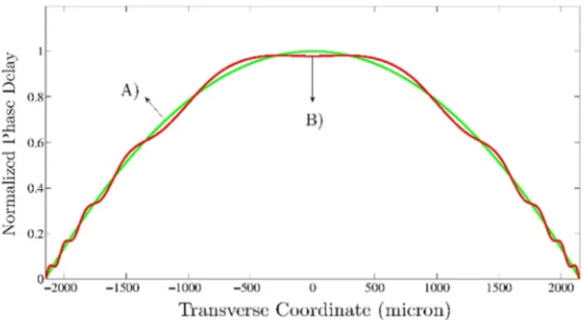
Fig. 2. Comparison of the unperturbed phase distribution (A) with an aperiodically perturbed phase distribution (B); the curve B) shows the cubic spline interpolation of the spatial chirp
function
3. Result of the calculation
Eq. (14) describes the temporal and spatial properties of the focused pulse in the vicinity of the focus. Plane waves (Fourier components) incident on the mirror and propagating toward the focal plane. The superposition of the diffraction patterns has been numerically integrated using the parameters corresponding to the parabolic mirror and the light pulse: # 0.3 μm/fs (speed of light), 0.5 μm (central wavelength), s 10 fs (pulse duration), 2150 μm (2 is the diameter of the mirror),
5 — 10[˜ 1/μm (responsible for the shape of the parabolic mirror), 5 — 10™ μm (focal plane), 2 ƒn 1 110⁄ μm[. (1 ƒ⁄ n 691 μm spatial period), ℎ 0.1 modulation depth, b 0.1 2⁄ ≈ 0.0159 žm[.(chirping parameter), FWHM 2.8841 — 10¤μm (spatial width of the Gaussian type bell-curve).
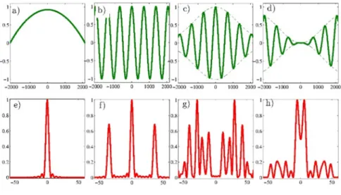
Fig. 3e shows that an unperturbed mirror (Fig. 3a) creates the Fourier transform (sinc function) of the rectangular pupil function as expected. Numerical calculations show that the slightly periodic deviation from the perfect mirror shape leads a spatial dispersion of the pulse in the neighborhood of the focus as it can be seen in Fig. 3f - Fig. 3h. The phase disturbance can be characterized by a harmonic function. Since the value of modulation depth is ℎ 0.1 the maximum deviation from the perfect parabolic phase delay is 10%. It turns out that the effects of the mirror waviness are similar to the effects of sinusoidal phase grating. A thin sinusoidal phase grating can be characterized by the amplitude transmittance function as follows:
A 0G2¥7JKL= (†¦§H?Irect GH)I, (19)
where for simplicity it is assumed that the grating structure is bounded by an aperture of width 2a. The parameter • represents the peak to peak change of phase transmittance across the screen, and ƒ¬W is the spatial frequency of the grating. If the grating is illuminated by a unit-amplitude, normally incident plane wave, then the field distribution immediately behind the screen is given precisely by Eq. (19). As it can be seen in Fig. 3f the introduction of the harmonic phase perturbation has thus deflected energy out of the zero order into multitude of higher orders. Note that the strengths of the various orders are symmetric about the zero order.
Fig. 3. An unperturbed parabolic phase distribution is depicted in plot a); the corresponding intensity distribution can be seen in plot e); plot e) shows the Fraunhofer intensity distribution of the pulse in focal plane; the following subplots in the top row b)-d) are periodic functions, which are modifying the original parabolic phase distribution; the subplots in the bottom row are the
relevant intensity distributions of the modulated pulses in the focal plane
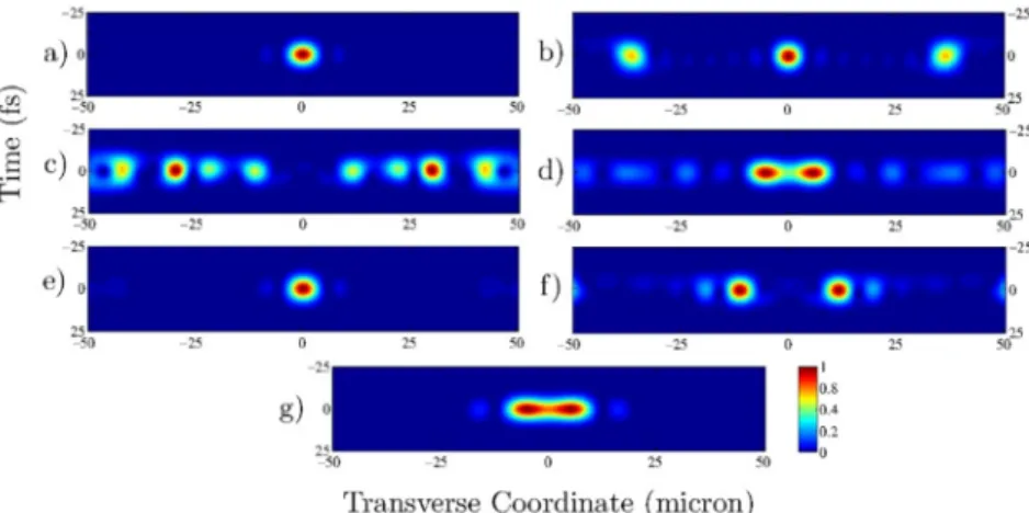
Introduction of the harmonic phase disturbance leads the redistribution of energy between the side lobes. Due to the field modulation the energy is scattered to a larger volume surrounding the focal point compared to the unperturbed case. As mentioned earlier there are many other possibilities to introduce phase-disturbance deviating from the perfect mirror shape, for example, the envelope of the harmonic phase perturbation function can be modulated by a Gaussian type bell-curve (see Fig. 3c). Aperiodic waviness can be realized by introducing spatially chirped cosine function instead of periodic one as it can be seen in Fig. 4a. In order to emphasize the perturbation in the center of the mirror let the envelope of the chirp function is a Gaussian type bell-curve (see Fig. 4b). Due to the aperiodic phase perturbation with the effect of amplitude diminishing towards the edges the energy may leave the central region (zero order) and forms a double peak in the vicinity of the optical axis as it depicted by Fig. 4e
and Fig. 5f. Creating dark central region on the optical axis can be useful because a beam of this kind has applications in optical tweezers for trapping particles with refractive index lower than the surrounding medium, where the gradient force will be directed toward the region of lowest intensity. Fig. 5 shows the complete temporal- spatial distributions of all pulses, which were shown only in the spatial regime in Fig. 3 and in Fig. 4.
Fig. 4. The subplots in the top row a)-c) are the non-periodic functions which are modifying the original parabolic phase distribution; the subplots in the bottom row d)-f) are the intensity
distributions of the aperiodically modulated pulses in the spatial domain
Fig. 5. Temporal-spatial intensity distribution of the focused pulses in the focal plane
If the amplitude of the chirp function increases towards the edges of the mirror two almost merged peak can be observed in the central region (see Fig. 4f and Fig. 5g).
During the simulation significant temporal broadening was not observed, however in case of extremely short pulses of a few optical cycles incident on a perfectly conducting spherical mirror under the focusing process significant temporal spreading was predicted, which avoids a fully compensated pulse [17]. In the current study the number of complete optical cycles is exactly six, which cannot be considered as a few optical cycles. The results of the current study may contribute to the field of generation and propagation of attosecond pulses [18]-[21].
4. Conclusion
The propagation of a focused ultra-short light pulse was studied in the framework of scalar diffraction theory. The light pulse was focused by an imperfect (wavy) parabolic mirror. Due to the harmonic and aperiodic phase perturbation the temporal and spatial behavior of the wave field is distorted in the vicinity of the focal plane. It turned out that the effects of the mirror waviness are similar to the effects of sinusoidal phase grating.
The phase perturbation leads the redistribution of energy between the side lobes. The harmonic phase perturbation has thus deflected energy out of the zero order into multitude of higher orders. It was shown that in case of aperiodic phase perturbation a double peak is formed close to the optical axis, creating dark central region on the optical axis can be useful because a pulse of this kind has applications in optical tweezers for trapping particles. Other possible areas of application are the surface processing and micro lithography.
Open Access statement
This is an open-access article distributed under the terms of the Creative Commons Attribution 4.0 International License (https://creativecommons.org/licenses/by/4.0/), which permits unrestricted use, distribution, and reproduction in any medium, provided the original author and source are credited, a link to the CC License is provided, and changes - if any - are indicated. (SID_1)
References
[1] Bor Zs. Distortion of femtosecond laser pulses in lenses and lens systems, Joural Modern Optics, Vol. 35, 1988, pp. 1907‒1918.
[2] Bor Zs., Horváth Z. L. Distortion of femtosecond pulses in lenses. Wave optical description, Optics Communications, Vol. 94, No. 4, 1992, pp. 249‒258.
[3] Kempe M., Stamm U., Wilhelmi B., Rudolph W. Spatial and temporal transformation of femtosecond laser pulses by lenses and lens systems, Journal of the Optical Society of America B, Vol. 9, No. 7, 1992, pp. 1158‒1165.
[4] Kempe M., Stamm U., Wilhelmi B. Spatial and temporal transformation of femtosecond laser pulses by lenses with annular aperture, Optics Communications, Vol. 89, No. 2-4, 1992, pp. 119‒125.
[5] Horváth Z. L., Bor Zs. Focusing of femtosecond pulses having Gaussian spatial distribution, Optics Communications, Vol. 100, No. 1-4, 1993, pp. 6‒12.
[6] Horváth Z. L., Bor Zs. Behavior of femtosecond pulses on the optical axis of a lens.
Analytical description, Optics Communications, Vol. 108, No. 4-6, 1994, pp. 333‒342.
[7] Horváth Z. L., Bor Zs. Reshaping of femtosecond pulses by the Gouy phase shift, Phys.
Rev. E, Vol. 60, No. 2, Pt. B, 1999, pp. 2337‒2346.
[8] Horváth Z. L., Bor Zs. Diffraction of short pulses with boundary diffraction wave theory, Phys. Rev. E, Vol. 63, No. 2, Pt. 2, 2001, Paper No. 026601.
[9] Ignatowsky V. S. Diffraction by a parabolic mirror having arbitrary opening, Trans. Opt.
Inst. Petrograd, Vol. 1, No. 4, 1919, pages 1‒30.
[10] Wolf E. Electromagnetic diffraction in optical systems, I, An integral representation of the image field, Proc. R. Soc. A, Math. Phys. Sci, Vol. 253, No. 1274, 1959, pp. 349‒357.
[11] Richards B., Wolf E. Electromagnetic diffraction in optical systems, II, Stucture of the image field in an aplanatic system, Proc. R. Soc. A, Math. Phys. Sci, Vol. 253, No. 1274, 1959, pp. 358‒379.
[12] Hecht E. Optics, Pearson Education, Harlow, 2017.
[13] Born M., Wolf E. Principles of optics, Cambridge University Press, Cambridge, 2019.
[14] Etlinger J., Rák O., Zagorácz M., Máder M. P. Revit add-on modification with simple graphical parameters, Pollack Periodica, Vol. 13, No. 3, 2018, pp. 73‒81.
[15] Szűcs Á. I. Improving graphics programming with shader tests, Pollack Periodica, Vol. 14, No. 1, 2019, pp. 35‒46.
[16] Honti R., Erdélyi J., Kopáčik A. Automation of cylinder segmentation from point cloud data, Pollack Periodica, Vol. 14, No. 3, 2019, pp. 189‒200.
[17] Anaya-Vera S., García-Martínez L., Rosete-Auiglar M., Bruce N. C., Garduño-Mejia J.
Temporal spreading generated by diffraction in the focusing of ultrashort light pulses with perfectly conducting spherical mirrors, Journal of the Optical Society of America A, Vol. 30, No. 8, 2013, pp. 1620‒1626.
[18] Ma G., Dallari W., Borot A., Krausz F., Yu W., Tsakiris G. D., Veisz L. Intense isolated attosecond pulse generation from relativistic laser plasmas using few-cycle laser pulses, Physics of Plasmas, Vol. 22, No. 3, 2015, Paper No. 033105.
[19] Hernández-García C., Popmintchev T., Murnane M. M., Kapteyn H. C., Plaja L., Becker A., Jaron-Becker A. Isolated broadband attosecond pulse generation with near- and mid- infrared driver pulses via time-gated phase matching, Optics Express, Vol. 25, No. 10, 2017, pp. 11855‒11866.
[20] Kessel A., Leshchenko E. V., Jahn O., Krüger M., Münzer A., Schwarz A., Pervak V., Trubetskov M., Trushin A. S., Krausz F., Major Zs., Karsch S. Relativistic few-cycle pulses with high contrast from picosecond-pumped OPCPA, Optica, Vol. 5, No. 4, 2018, pp. 434‒442.
[21] Jahn O., Leshchenko E. V., Tzallas P., Kessel A., Krüger M., Münzer A., Trushin A. S., Tsakiris D. G., Kahaly S., Kormin D., Veisz L., Pervak V., Krausz F., Major Zs., Karsch S.
Towards intense isolated attosecond pulses from relativistic surface high harmonics, Optica, Vol. 6, No. 3, 2019, pp. 280‒287.