FUNDAMENTAL TECHNIQUES: FLUIDS B. A . Toms
I. F l o w through Pipes 4 7 5 1. Experiments in Pipe F l o w 4 7 6
a. A p p a r a t u s 4 7 6 b. M e t h o d s 4 7 7 2 . D e r i v a t i o n of Pressure Gradient v s . R a t e of F l o w R e l a t i o n s 4 7 9
3. O c c u r r e n c e of Laminar F l o w 4 8 1 4 . Interpretation of O b s e r v e d Pressure Gradient v s . R a t e of F l o w R e l a t i o n s . . 4 8 2
I I . F l o w B e t w e e n Coaxial Cylinders 4 8 6
1. Apparatus 4 8 7 2 . E x p e r i m e n t s I n v o l v i n g S t e a d y R o t a t i o n 4 9 3
3. Experiments I n v o l v i n g O s c i l l a t o r y M o t i o n 4 9 6
N o m e n c l a t u r e 5 3 5
I. Flow T h r o u g h Pipes
W e are concerned here with the study of the isothermal flow of liquids through straight narrow pipes, a t y p e of investigation first introduced, with conspicuous and far-reaching success, b y Poiseuille1 just over a century a g o . T h e m o t i o n s of liquids, and m o r e especially of n o n - N e w t o n i a n liquids, in wide and in curved pipes are m o r e complicated and less well understood.
If steady laminar flow through a straight pipe of circular section (radius a) b e observed, the m a c r o s c o p i c rheological properties of the material can be deduced, in suitable cases, from simultaneous measurements of the v o l u m e rate of flow Q and the pressure gradient d o w n the pipe dp/dz.
I n the special case of a N e w t o n i a n liquid, the relationship between the measured quantities and the characteristic viscosity coefficient η' is ex- pressed b y Poiseuille's formula
, χα
4 dp λ / 1E q u a t i o n (1) also serves t o define an apparent viscosity coefficient for a non- N e w t o n i a n liquid in a single experiment, b u t this is an empirical quantity only, since it depends on the rate of flow and on the pipe diameter.
1 J. L. M . Poiseuille, Compt. rend. 1 1 , 9 6 1 , 1 0 4 1 ( 1 8 4 0 ) ; 12, 1 1 2 ( 1 8 4 1 ) ; 15, 1 1 6 7 ( 1 8 4 2 ) ; Wem. Savants Etrangers 9, 433 ( 1 8 4 6 ) .
475
476 Β . Α . T O M S
W h e n N e w t o n i a n behavior does n o t prevail, or if the rheological proper- ties are u n k n o w n (as in the case of a new artificial liquid), a different treat- ment of the observed Q, dp/dz data is required in order that information of fundamental significance m a y be procured. I n the absence of a defin- itive m e t h o d it is appropriate, in the present context, t o direct attention t o a recently proposed analytical p r o c e d u r e2 which merits exploitation, par- ticularly in relation t o the flow of suspensions of anisometric particles.
In principle, this new m e t h o d enables the stress v s . rate of strain relation in the bulk of the material remote from boundaries t o be d e d u c e d when the flow of a n o n - N e w t o n i a n liquid is complicated b y a wall effect.
W e shall n o w consider some aspects of the c o n d u c t and interpretation of exploratory experiments in pipe flow.
1. EX P E R I M E N T S I N PI P E FL O W
a. Apparatus
T h e restriction that an experimental pipe must b e " n a r r o w " is con- veniently imprecise, for in practice a variety of bore sizes will usually be needed. Capillary-bore tubes (a < 0 . 0 5 c m . ) are required for m o s t w o r k on low-viscosity liquids {η' < 0 . 1 poise, s a y ) , and their use is indicated when- ever information is sought on flow at large stresses; but flow at small stresses and m u c h of the behavior of liquids of large viscosity ( 1 < η' < 1 0 0 poise, say) are more easily studied in wider pipes. It is therefore peculiarly difficult t o select pipes for an extensive investigation of the flow of a non- N e w t o n i a n liquid with widely variable viscosity, and the choice has almost always t o be m a d e empirically.
T h e length I of an experimental pipe is also subject t o restriction. T h i s matter will be discussed later (see Section I, 2 ) .
T h e characteristics of the bore of the pipe must always be k n o w n as exactly as possible (determination of the mean radius a, for instance, is especially important, since Q α α4) . T h e required observations are facilitated b y having the ends of the pipe cut off square with respect t o the main axis of the b o r e : the length of the bore is then well defined, and its true cross section exposed. T h e shape and principal dimensions of the cross section at b o t h ends can b e determined directly with a measuring m i c r o s c o p e ; b u t a better indication of the uniformity of the bore, and a m o r e accurate esti- mate of a, can o b v i o u s l y be secured, after the flow experiments have been completed, b y cutting the pipe i n t o several pieces and then examining the ends of these in turn. Destruction of the pipe can, of course, be a v o i d e d . In the case of capillary glass pipes, for example, b o t h a and the uniformity of the bore are c o m m o n l y determined b y the classic 'mercury-thread'
2 J. G . O l d r o y d , J. Colloid Sei. 4, 333 (1949).
method. In the case of pipes which are not of capillary bore a can be de- duced b y determining the difference in mass between the pipe and a solid cylinder made of the same material and having identical external dimen- sions; the density of the material must, of course, be known with sufficient accuracy, and the necessary assumption that the bore is a right circular cylinder should be justified.
These topics, and the correction of equation (1) for ellipsicity and conical- ness of the pipe bore, are discussed b y B i n g h a m4 and Barr.5
Smooth-bore pipes having 0.05 c m . < a < 0.5 c m . will often be satis- factory for the kind of work envisaged here. Such pipes are nowadays manu- factured from a variety of metals b y methods which ensure that the bore is both unrestricted and very nearly a right circular cylinder; "precision- b o r e " glass pipes, with internal dimensions accurately specified b y the makers, are available.6
b. Methods
Fundamentally, every quantitative experiment in pipe flow entails si- multaneous observations of the volume rate of flow Q ( c m .3/ s e c . ) through the pipe and the associated difference of hydrostatic pressure Ap ( d y n e s / c m .2) between its ends. It is always best t o measure these quan- tities as directly as possible. W e shall refer briefly t o t w o general methods, one introduced b y Brückner7 and the other b y C o u e t t e :8 these are readily applicable, and both have been widely used with a variety of empirical modifications.
It must always be arranged that the liquid enters and leaves the pipe bore in a well-defined (and therefore reproducible) manner: this can be achieved, with the practical advantage of having similar conditions of entry and exit, b y fixing the ends of the pipe into t w o vessels of the same shape and size.
In Bruckner's method, this simple assembly, with the pipe horizontal, is partially filled with the experimental liquid and joined in a pneumatic circuit designed so that the air pressure a b o v e the liquid surface in one reservoir can be varied independently of that in the other. (For example, it might be arranged, as shown in Fig. 1, that one reservoir is open t o the atmosphere while the other is connected to a large vessel in which a constant air pressure, different from atmospheric, is maintained). T h e liquid can then be caused t o flow through the pipe at constant rate, and in either direction ;
3 G. Jaeger, Wiss. Abhandl. physik. tech. Reichsanstaldt 2, 381 (1895).
4 E . C . Bingham, "Fluidity and P l a s t i c i t y . " McGraw-Hill, N e w Y o r k , 1922.
5 G. Barr, " A Monograph of V i s c o m e t r y . " Oxford Univ. Press, N e w Y o r k , 1931.
6 Anonymous, / . Sei. Instr. 22, 116 (1945).
7 H . Brückner, Wied. Ann. 42, 287 (1891).
8 M . Couette, Compt. rend. 107, 388 (1888); Ann. chim. phys. 21, 433 (1890).
478 Β . Α . T O M S
Air reservoir Manometer
h'-
ho
F I G . 1. A n experiment in p i p e flow. (After Brückner.7)
Q is determined b y measuring the time required for a known quantity of liquid, indicated b y t w o level marks (Λ', h")y t o enter or leave one of the reservoirs. If the liquid surface stands m i d w a y between the level marks when the air pressure is the same (e.g., atmospheric) in b o t h reservoirs, the net change of hydrostatic pressure resulting from the transference of liquid will b e zero: Ap can then b e measured directly b y means of a suitable m a n o m e t e r in the pneumatic circuit. T h e principle of this m e t h o d has found important application in precision v i s c o m e t r y ; it has also been e m - p l o y e d in experiments i n v o l v i n g relatively large values of Q .11
W h e n data on flow through t w o (or m o r e ) different lengths of pipe having the same radius are required (see Section I, 2 ) , it will often b e convenient if the necessary observations can b e m a d e in a single experiment. T h e es- sential features of C o u e t t e ' s m e t h o d , which enables this t o b e d o n e , are represented schematically in Fig. 2 . I t is seen that the basic vessel-pipe- vessel assembly is repeated so that the mainstream, flowing at constant rate Q, passes through the different pipes successively. ( A variety of meth- ods exists for controlling the mainstream, and for measuring Q: several of these are described b y B i n g h a m4 and Barr,5 and there is the n o t e w o r t h y procedure of C o e1 2. ) T h e relevant hydrostatic pressures are indicated b y manometers set in this hydraulic circuit: the value of Ap for each p i p e can thus be d e d u c e d p r o v i d e d the density of the experimental liquid is k n o w n . (As indicated in Fig. 2, the working range of the m a n o m e t e r s can b e ex- tended b y uniformly v a r y i n g the effective atmospheric pressure.) T h i s
9 T . T h o r p e and J. R o d g e r , Phil. Trans. Roy. Soc. A185, 397 (1894).
1 0 E . C . Bingham and G . F. W h i t e , Z. physik. Chem. 80, 670 (1912).
11 B . A . T o m s , J. Colloid Sei. 4, 511 (1949).
1 2 J. R . Coe, Physics 4, 274 (1933).
Air r e s e r v o i r
t
h
h-I r—
h—>I
F I G . 2 . A n experiment in p i p e flow. (After C o u e t t e .8)
m e t h o d has been used in precision v i s c o m e t r y ,8 , 13 t h o u g h its application is n o t restricted in principle t o cases in which Q is small.
I n e v e r y experiment, the temperature of the experimental liquid m u s t b e k n o w n and maintained constant : this can b e achieved b y immersing the flow apparatus in a b a t h of a liquid the temperature of which can b e c o n - trolled t o within, say, ± 0 . 0 1 ° .
2. DE R I V A T I O N O F PR E S S U R E GR A D I E N T V S . RA T E O F FL O W RE L A T I O N S
A n experiment in pipe flow yields, in the first instance, related values of the observable quantities Ap and Q (see Section I, 1 ) . If o n l y one pipe is used, the corresponding values of dp/dz and Q, w h i c h are required t o define the viscosity of the material [see equation ( 1 ) ] , can be deduced directly from the primary data only b y assuming (i) that viscous flow prevails uniformly throughout and is confined t o the bore of the pipe, and (ii) that energy is expended solely in o v e r c o m i n g the v i s c o u s resistance, or friction, of the liquid. B u t in practice neither of these assumptions is valid, for w h e n a liquid is caused t o flow through a pipe from one vessel t o another, there occurs (a) relative m o t i o n between elements of liquid before t h e y enter the pipe, and (b) anomalous flow w h i c h arises at, and persists for s o m e distance downstream of, the pipe entrance (i.e. steady laminar flow does n o t d e v e l o p instantaneously); and, of course, the t e m p o r a r y acquisition of kinetic energy b y the liquid must also b e taken into a c c o u n t . I t follows that n o t
1 3 S. E r k , Forschungsarb. Ver. deut. Ing. N o . 2 8 8 ( 1 9 2 7 ) ; S. E r k and A . S c h m i d t , Physik. Ζ. 37, 4 8 9 ( 1 9 3 6 ) .
480 Β . Α . T O M S
all of the energy expended in an experiment is used t o maintain steady laminar flow within the pipe. A n d so, although the error incurred b y putting dp/dz = Ap/l m a y well be negligible if Q is sufficiently small and the pipe is sufficiently long and narrow (cf. Poiseuille1), it is in principle necessary t o correct a crude observation of Ap before evaluation of η can be under- taken; and, of course, the need for correction grows as Q is increased and I decreased. A t the present time, however, it is n o t k n o w n h o w t o m a k e the required correction in the case of a n o n - N e w t o n i a n liquid. Indeed, only approximate solutions of the relevant h y d r o d y n a m i c a l problems have so far been achieved in the simpler case of a N e w t o n i a n liquid.5 -1 4 T h e p r o b - lem of analyzing pipe flow data must therefore be approached in another w a y if extensive studies in n o n - N e w t o n i a n flow are t o be undertaken.
W h e n a liquid flows through a pipe at constant rate, its kinetic energy and the magnitude of the "entrance effects" (more generally, " e n d effects") are determined b y the v o l u m e rate of flow; they d o n o t depend upon the length of the pipe. It follows that the difficulties resulting from end effects and the gain of kinetic energy b y the liquid can be entirely eliminated b y combining suitable observations of ap and Q obtained from experiments with different separate lengths of pipe, all of the same form and all having the same bore radius. T h u s , if the pressure heads required t o maintain a v o l u m e rate of flow Q in each of t w o lengths of pipe Γ, l" (Z" > / ' ) , b o t h of radius a, are Apf, Ap", respectively, then the relationship
dp _ Ap" - Ap , .
Tz ~ V - V [ ]
will b e valid p r o v i d e d that steady flow is achieved within the length of the shorter pipe. In order t o discover whether this essential condition has been satisfied or not, Ap"'(ff) must b e measured in a third length of pipe V"
( > Z " ) ; only if
Ap — Ap _ Ap — Ap _ Ap — Ap , . I" - V V" - V V" - V { }
will it b e justifiable t o use equation ( 2 ) t o evaluate dp/dz(Q). I t is seen that this ingenious procedure, which was first introduced b y C o u e t t e ,8 enables the proper relationship between Q and dp/dz t o be constructed for any liquid and for a n y t y p e of steady flow.
I n practice, and particularly in w o r k with n o n - N e w t o n i a n liquids for which entrance effects can b e v e r y large, it will sometimes be necessary t o increase the lengths of experimental pipes until (3) is satisfied. Pipes for which 100 < l/a < 1000 are generally serviceable, b u t o p t i m u m lengths have almost always t o be fixed empirically.
1 4 S. Goldstein ( e d . ) , " M o d e r n D e v e l o p m e n t s in Fluid D y n a m i c s , " V o l . 1, Oxford U n i v . Press, N e w Y o r k , 1950.
3. OC C U R R E N C E O F LA M I N A R FL O W
W h e n laminar flow prevails in a pipe (i.e., w h e n e v e r y particle of the fluid m a y b e assumed t o m o v e in a straight line parallel t o the axis of the p i p e ) , the pressure gradient is proportional t o the first p o w e r of the v e l o c i t y , and the distribution of v e l o c i t y across a section of the bore is p a r a b o l i c .14 T h i s special kind of fluid m o t i o n seldom occurs in wide pipes and n o t always in narrow o n e s : w h e n it is replaced b y nonlaminar flow, none of the condi- tions mentioned is fulfilled and, of course, (1) ceases t o be the relevant rela- tionship between pressure gradient and rate of flow. It is therefore of c o n - siderable practical importance t o b e able t o distinguish laminar from nonlaminar flow and also t o b e apprised of the conditions under which each regime m a y b e expected t o persist. T h e s e matters h a v e received consider- able attention in the literature.
T h e circumstances of the transition from laminar t o nonlaminar flow in pipes were first elucidated b y Osborne R e y n o l d s15 w h o discovered that the m o d e of m o t i o n can b e indicated (in a transparent p i p e ) b y introducing a filament of colored liquid into the mainstream. If laminar flow prevails, the filament extends d o w n the pipe in a straight line, increasing in width o n l y v e r y slowly through diffusion. B u t if the speed of flow is increased, a stage is reached at which the straight-line m o t i o n breaks d o w n : the colored fila- m e n t then mixes with the mainstream and the pipe appears t o b e filled with color, while a close examination reveals that the stream is constantly varying, with irregular m o t i o n s across the bore. B y c o m b i n i n g this elegant m e t h o d of detection with appropriate analysis of the corresponding pressure gradient v s . rate of flow data, R e y n o l d s was able t o s h o w that the conditions for the change from laminar t o nonlaminar flow, and v i c e versa, can b e defined in terms of a dimensionless parameter (the Reynolds number),
which is seen t o d e p e n d u p o n the diameter of the p i p e b o r e , the density and viscosity of the fluid, and the mean v e l o c i t y of flow.
Experiments with N e w t o n i a n liquids1 5"17 h a v e shown that the t y p e of nonlaminar flow which is ordinarily regarded as turbulence c a n n o t persist in a p i p e unless R > 2000, a p p r o x i m a t e l y . L a m i n a r flow, on the other hand, occurs w h e n e v e r R < 1000, and usually remains the preferred t y p e of m o t i o n until R = 2000, a p p r o x i m a t e l y . S o m e cases of departure from
1 5 O . R e y n o l d s , Phil. Trans. Roy. Soc. 174, 935 (1883); Sei. Papers, 2 , 51.
1 6 T . E . Stanton and J. R . Pannell, Phil. Trans. Roy. Soc. A214, 199 (1914).
1 7 L. Schiller, Physik. Z. 3, 412 (1920); 25, 541 (1924); Forschungsarb. Ver. deut.
Ing. N o . 248 (1922).
( 4 )
4 8 2 Β . Α . T O M S
strictly rectilinear m o t i o n when 1 0 0 0 < R < 2 0 0 0 h a v e been r e p o r t e d ,1 8 , 19 b u t there is other e v i d e n c e1 5 , 20 that laminar flow can persist at v e r y large values of R ( 1 04, or m o r e ) if special care is taken t o a v o i d a n y disturbance in the first reservoir or at the entry t o the p i p e . H o w e v e r , in ordinary prac- tice b r e a k d o w n is t o b e anticipated w h e n R > 2 0 0 0 .
W h i l e it is reasonable t o suppose that these conclusions are relevant t o the behavior of n o n - N e w t o n i a n liquids, it is n o t k n o w n h o w R should b e calculated for an experiment i n v o l v i n g a liquid of variable viscosity coeffi- cient. Nevertheless, there are grounds for thinking that R = constant can be m a d e a criterion for the b r e a k d o w n of laminar flow if an apparent vis- cosity coefficient appropriate t o the experimental conditions is substi- t u t e d for η' in equation ( 4 ) . T h u s the b r e a k d o w n of laminar flow in certain p o l y m e r solutions has been shown t o occur at Ri = 2 0 0 0 (i.e., the same criti- cal R e y n o l d s n u m b e r as found for the solvent—a N e w t o n i a n liquid—
under the same conditions) b y assuming that the relevant viscosity coeffi- cient was that measured at large rates of shear i.e., η\ (see Section I, 4 ) , and a similar result has been obtained in the case of a benzopurpurin s o l .21
4 . IN T E R P R E T A T I O N O F OB S E R V E D PR E S S U R E GR A D I E N T V S . RA T E O F FL O W RE L A T I O N S
W h e n the pressure gradient αφ/dz in the region of steady laminar flow is k n o w n as a function of the v o l u m e rate of flow Q for a straight pipe of radius a (see Section I, 2 ) , the characteristic rheological properties of the material remain t o be d e d u c e d . T h i s is easily accomplished for a N e w - tonian liquid; b u t in the case of a n o n - N e w t o n i a n liquid, the possibility that the experimental observations m a y b e c o m p l i c a t e d b y anomalous behavior near the pipe wall has always t o b e considered, for the wall intro- duces a preferred direction in the material, and it m a y happen that the rate of shear near the wall is consequently n o t a function of shear stress alone.
( I t is conceivable, for example, that an otherwise isotropic material might b e h a v e anisotropically in a thin layer close t o a wall if the rotational free- d o m of rod- or platelike particles in the material were restricted b y p r o x - imity t o a rigid b o u n d a r y2 2. ) T h u s in principle one must b e able b o t h t o detect and measure a wall effect in pipe flow and t o d e d u c e the charac- teristic rheological properties in the bulk of the material r e m o t e from boundaries (i.e., in an isotropic c o n d i t i o n ) when a wall effect is present.
1 8 A . H . Nissan, / . Inst. Petroleum 28, 257 (1942).
1 9 R . R . R o t h f u s and R . S. Prengle, Ind. Eng. Chem. 44, 1683 (1952).
2 0 Η . T . Barnes and E. G. Coker, Proc. Roy. Soc. (London) A74, 341 (1905).
2 1 A . M . Binnie, Proc. Phys. Soc. (London) 57 , 390 (1945); A . M . Binnie and J. S.
Fowler, Proc. Roy. Soc. (London) A192, 32 (1948).
2 2 F . R . Eirich, H . Margaretha, and M . B u n z l , Kolloid-Z. 75, 20 (1936).
T h e nature and extent of present achievement in the theoretical treatment of this difficult p r o b l e m are indicated b y 0 1 d r o y d ;2 2a the earlier d e v e l o p - ments h a v e been e x p o u n d e d b y S c o t t B l a i r23 and R e i n e r .24 F r o m the experimental standpoint, w e m a y profitably consider a n e w analytical procedure suggested b y O l d r o y d ,2 for this has certain advantages o v e r others and m a y replace t h e m .
It is possible t o detect anomalous flow of a n o n - N e w t o n i a n liquid near a rigid b o u n d a r y b y plotting the apparent fluidity 1/77' [as given b y equation (1)] against the shear stress at the wall τα( = ^ α dp/dz), or s o m e function of TA , in laminar flow through pipes of various diameters. If the properties of the liquid in shear are everywhere specified b y a unique stress v s . rate of strain relationship (i.e., there is no wall effect), all the plotted points should lie o n a single curve, Ι/η' = F(TA), in the region of laminar flow (the points for the different pipes will, of course, separately depart from this curve at values of τα larger than that corresponding t o the b r e a k d o w n of laminar flow in each p i p e ) . A wall effect is indicated if distinct (1/V, τα) curves arise from different diameters of p i p e ; it can b e measured b y an effective slip coefficient f ( r0) , which is the effective v e l o c i t y of slip per unit shear stress at a wall, p r o v i d e d the relative displacements of the curves are consistent with the general relation
- , = ^ + F ( r . ) ( 5 ) η a
In such a case, and if the curves are sufficiently well defined, equation (5) can b e used t o obtain F(TA) and f ( ra) , for if Ι/η' is plotted against 1/a for selected constant values of ra , the points so obtained should lie on a straight line with slope 4 f ( ra) and intercept F(TA) on the 1/77' axis. T h u s the magni- tude of the wall effect can b e assessed, and the curve 1/V = F(ra) can be constructed and used, as for a liquid n o t showing wall effects, t o obtain the stress v s . rate of strain relationship for the material remote from boundaries. T h e m a c r o s c o p i c flow properties of the material are then specified completely.
T h i s m e t h o d of interpreting observed pressure gradient v s . rate of flow relations is laborious, b u t it has already served t o detect and measure a wall effect in solutions of a linear p o l y m e r .11 W e shall n o w consider this application, partly t o illustrate O l d r o y d ' s m e t h o d and partly t o indicate that results obtained b y it are consistent with those deduced b y another
2 2a J. G. O l d r o y d , in " R h e o l o g y , T h e o r y and A p p l i c a t i o n s " (F. R . Eirich, ed.), V o l . I, C h a p t e r 16, A c a d e m i c Press, N e w Y o r k , 1956.
2 3 G . W . S c o t t Blair, " I n t r o d u c t i o n t o Industrial R h e o l o g y . " Churchill, L o n d o n , 1938.
2 4 M . Reiner, " D e f o r m a t i o n and F l o w . " L e w i s , L o n d o n , 1949.
484 Β . Α . T O M S
150
100
50
0Q
0 0.05 0.10 0.15 0.20 0.25 0.30
FI G . 3. O b s e r v e d relations between Ι/η' and l/r0 in the case of a N e w t o n i a n l i q u i d . ( R e p r o d u c e d b y c o u r t e s y / . Colloid Set.)
oq
150 ι . a
itu
1 ο ' Csi
^ 100 _ | u
' < £
50
> o o0 c to
U 1 I I I I I
0 0.05 0.10 0.15 0.20 0.25
Ι / τ .
FI G . 4. O b s e r v e d relations between Ι/η' and l/ra in the case of a n o n - N e w t o n i a n liquid. N o wall effect. ( R e p r o d u c e d b y c o u r t e s y J. Colloid Sei.)
procedure of similar scope which was proposed earlier b y Schofield and S c o t t B l a i r .2 3 , 25
T o m s1 1 observed the flow of dilute solutions of poly (methyl methacrylate) in monochlorbenzene [(η) = 39 liter/gm.] through straight metal pipes of t w o diameters at 25°. T h e experimental results, some of which are displayed in Figs. 3 t o 5, were represented b y plotting Ι/η' against l / ra (i.e., a c o n - venient function of the shear stress at the wall) for Tube A (a = 0.202 c m . )
2 5 R . K . Schofield and G . W . S c o t t Blair, Phys. Chem. 34, 248 (1930); 35, 1212 (1931).
0 . 0 0 5 ι 0 . 0 1 0
ι
0 . 0 1 5 1 / τα
ι
0 . 0 2 0 0 . 0 2 5
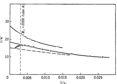
FIG. 5. Observed relations b e t w e e n Ι/η' and 1/τα in the case of a n o n - N e w t o n i a n liquid. Wall effect present ( R e p r o d u c e d b y c o u r t e s y J. Colloid Sei.)
and Tube Β (α = 0 . 0 6 45 c m . ) . T h e a c c u r a c y and consistency of results o b - tained with the t w o sizes of pipe are indicated in Fig. 3 which refers t o ex- periments with the pure solvent. M o n o c h l o r b e n z e n e is seen t o b e a N e w - tonian liquid (as is well k n o w n ) , and the observed constant value, Ι/η' — 132, is in g o o d agreement with the k n o w n fluidity of the material at 25°.
It is also evident that b r e a k d o w n of laminar flow occurred in b o t h pipes at the same R e y n o l d s number, Rx = 2000, and this, of course, is the critical value c o m m o n l y observed when the ends of the pipe are cut off square as in the present case.
T h e results obtained with a solution containing 2.5 g m . of p o l y m e r per liter are shown in Fig. 4. T h e fact that a single s m o o t h curve can b e drawn through all the points corresponding t o laminar flow is evidence that there was n o anomalous behavior near a wall; and the significant departure of this curve from the form Ι/η' = constant is a measure of the extent t o which the liquid was n o t N e w t o n i a n . T h e analytical procedure of Schofield and S c o t t Blair also indicated the absence of a wall effect and g a v e the same limiting value, 1/η\ = 75, for the fluidity at v e r y large stresses (i.e., l/τα —> 0 ) . It is n o t e w o r t h y that the critical value of R e y n o l d s number p r o v e d t o be 2000 in b o t h pipes when the observed value of η\ was used in the calculations (see Section I, 3 ) .
T h e distinct ( 1 / V , l / ra) curves in Fig. 5, which refer t o experiments with a solution containing 10 g m . of p o l y m e r per liter, are consistent with the o c - currence of a wall effect of the t y p e envisaged b y O l d r o y d . T h e broken curve in the same figure represents Ι/η' = F ( l / ra) and gives 1/η\ = 15: as before, when this limiting value is used t o calculate R e y n o l d s number, Äi = 2000
486 Β . Α . T O M S
marks the b r e a k d o w n of laminar flow, at a n y rate in T u b e A (the critical conditions were n o t attained in the narrower p i p e ) . T h e effective slip c o - efficient increased with r0 and attained, at large values of τα , a limiting value fi = 0.2, w h i c h means that the effective v e l o c i t y of slip in these ex- periments was n o t b o u n d e d but tended t o infinity with the shear stress at the wall. It is therefore interesting t o note that w h e n the experimental data were analyzed b y the m e t h o d of Schofield and S c o t t Blair, the presence of a wall effect was confirmed, and their slip parameter σ0 could be identified with f ι .
II. Flow B e t w e e n C o a x i a l C y l i n d e r s
W e are concerned here with the study of certain aspects of the behavior of a liquid when it is sheared isothermally in a narrow annulus between long vertical coaxial cylinders. Under these conditions, the material is observed in (as nearly as possible) a simple shearing m o t i o n , and it can b e arranged that end effects are relatively small.
It is well k n o w n that experiments in which one cylinder (preferably the outer o n e2 6) is rotated at various k n o w n constant speeds, and the torque o n the other cylinder is measured, can readily be interpreted t o give the vis- cosity of the liquid as a function of rate of shear, or shear stress; moreover, wall effects can be detected and measured b y comparing observations on the same liquid in annular gaps of different widths. B u t a single variable viscosity coefficient associated with an effective slip coefficient (which, of course, m a y b e zero) does not suffice t o specify completely the properties in shear of an elasticoviscous liquid (a mobile liquid with elasticity of shape is envisaged). It is therefore convenient, and of considerable importance, that liquid elasticity can be detected and measured b y maintaining the outer cylinder in forced harmonic oscillations of small amplitude and recording the periodic torque on the inner one, or its m o t i o n when c o n - strained b y a suitable torsion wire. Experiments of this t y p e , which are n o t y e t practiced widely, depend on the fact that an elastic liquid, unlike an inelastic one, is able t o transmit transverse elastic w a v e s .2 2a
E v i d e n t l y , a suitably designed coaxial-cylinder apparatus has important advantages over a simple pipe, particularly when it is necessary t o discover the rheological properties of a liquid, or there is qualitative evidence of elasticity (e.g., in certain p o l y m e r solutions, air bubbles can b e seen t o recoil when stirring is stopped a b r u p t l y ) .
T h e first coaxial-cylinder viscometer was constructed b y C o u e t t e ,27 and the subsequent d e v e l o p m e n t of this t y p e of apparatus can b e followed in
2 6 G . I. T a y l o r , Phil. Trans. Roy. Soc. A223, 289 (1922); Proc. Roy. Soc. (London) A157, 546 (1936).
2 7 M . C o u e t t e , Ann. chim. phys. 2 1 , 433 (1890).
the accounts b y B a r r5 and M e r r i n g t o n .28 T h e recent introduction of the coaxial-cylinder elastoviscometer29'™ is an innovation w h i c h promises t o en- hance our k n o w l e d g e of the rheological properties of a variety of real liquids. I t is therefore appropriate t h a t w e should consider here h o w a liquid, and particularly an elastic liquid, can b e characterized in a simple shearing m o t i o n b y observing its behavior in an apparatus of this kind.
1. AP P A R A T U S
T h e coaxial-cylinder elastoviscometer described b y O l d r o y d , Straw- bridge, and T o m s3 2 consists essentially of (i) a vertical outer cylinder which can either b e rotated steadily at a n y speed within a wide range or put into forced harmonic oscillations at a w i d e range of k n o w n frequencies, with one of several possible k n o w n amplitudes; (ii) an inner cylinder, one of three with slightly different diameters, w h i c h can b e accurately aligned coaxially with the b o r e of the outer cylinder. In steady rotation, the torque on the inner cylinder is measured at different speeds. In oscillatory m o t i o n , the amplitude of oscillation of the inner cylinder, when constrained b y a torsion wire, is measured at different frequencies. ( I t is less easy t o arrange, alternatively, that the inner cylinder remains perfectly stationary while the forces on it are recorded.) In e v e r y experiment the temperature of the liquid in the annulus is k n o w n and maintained constant.
a. The Coaxial-Cylinder Assembly
T h e general appearance of this unit and the steel framework in w h i c h it is m o u n t e d are represented in F i g . 6; i m p o r t a n t details of the construction are shown in Figs. 7 and 8.
T h e coaxial-cylinder assembly is held in cross pieces extending between t w o tall pillars w h i c h are set in a b e d plate b o l t e d t o a concrete b l o c k . T h e cross pieces, which slide u p o n the pillars, are held apart and in position b y steel sleeves of the correct lengths. T h e t o p end of each pillar is threaded so that the whole framework can b e locked together rigidly b y tightening t w o hexagonal nuts. This m e t h o d of assembly facilitates adjustment and repair of the apparatus.
T h e outer cylinder, or " p o t , " w h i c h is m a d e entirely of stainless steel, is m o u n t e d in t w o ball bearings, and the setting is such that its longitudinal
2 8 A . C . Merrington, " V i s c o m e t r y . " Arnold, L o n d o n , 1949.
2 9 J. R . V a n Wazer and H . Goldberg, / . Appl. Phys. 18, 207 (1947).
3 0 H . Goldberg and O. Sandvik, Anal. Chem. 19, 123 (1947).
3 1 T . Nakagawa, Kagaku 20, 327 (1950) ; Chem. Soc. (Japan) 72, 759 (1951). [From Chem. Abstr. 46, 3368, 5933 (1952)].
3 2 J. G . O l d r o y d , D . J. Strawbridge, and B . A . T o m s , Proc. Phys. Soc. (London) B64, 44 (1951).
3 3 H . M a r k o v i t z , P . M . Y a v o r s k y , R . C . Harper, Jr., L . J. Zapas, and T . W . D e W i t t , Rev. Sei. Instr. 23, 430 (1952).
488 Β . Α . T O M S
Compressed A i r
Sleeve Torsion Head Sliding Oosspiece Locking Ring Upper Chuck
Lower Chuck Mirror Pülleu
x A i r Bearing Bob Spindle
VMater Jacket
Gland Mirror
Poî Drivino Shaft Sleeve
Steel Pillar Base Plate Concrete Bed 12 inches
7 + Γ
30 cm.
FI G . 6. T h e c o a x i a l - c y l i n d e r assembly and supporting framework. E l e v a t i o n . ( R e p r o d u c e d from Proc. Phy. Soc. b y kind permission of the Physical S o c i e t y . )
axis is as nearly vertical as possible; essentially, it is a t u b e closed at the b o t t o m end b y a plug, a d o w n w a r d extension of which forms the driving shaft (Fig. 7 ) . T h e interior has the form of a right circular cylinder and is 29.90 c m . in depth measured from rim t o floor. E a c h inner cylinder, or
" b o b , " is basically a solid right circular cylinder of D u r a l u m i n alloy, but the b o t t o m end is shaped t o a cone of large apical angle terminating in a cylindrical spigot (Fig. 7 ) : this design ensures that the b o t t o m end effect is small and that air bubbles are not trapped when the annulus is filled with liquid (see b e l o w ) . T h e three inner cylinders differ in diameter ( T a b l e I )
Air Bearing,
Boss
1Vtoter-îighî Gland Tap
FIG. 7. T h e coaxial-cylinder assembly. Detail. (After Oldroyd, Strawbridge, and T o m s .3 2) (Redrawn from Proc. Phys. Soc. b y kind permission of the Physical Society.)
490 Β . Α . T O M S
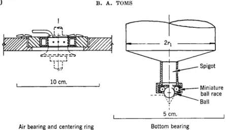
Air bearing and centering ring Bottom bearing
FIG. 8 . Details o f bearings supporting inner cylinder. (After 0 1 d r o y d , Strawb ridge, and T o m s .3 2) (Redrawn from Proc. Phys. Soc. b y kind permission o f the Physical Society.)
b u t h a v e the same length measured from the t o p surface t o the end of the cylindrical b o d y (25.40 c m . ) , or t o the end of the spigot (26.80 c m . ) .
T h e design and dimensions of the cylinders were chosen so that (1) liquids with viscosities between 10~2 and 102 poise, approximately,
could b e investigated;
(2) the radii of the inner and outer cylinders did n o t differ b y m o r e than 5 % , approximately, and annular gaps less than 0.05 c m . in width were a v o i d e d (the possible error in the alignment of long cylinders m a y n o t b e negligible with v e r y narrow gaps and, moreover, these are difficult t o fill with liquid) ;
(3) in oscillatory experiments, end effects, and particularly the b o t t o m end effect, could reasonably b e ignored (see Section I I , 3 ) .
T h e high degree of precision that was required, and achieved, in making the cylinders is shown b y the fact that, when t h e y had been h o n e d s m o o t h , the
T A B L E I
CHARACTERISTICS OF CYLINDERS AND ANNULI
Moment of Annulus
Cylinder Radius Inertia* Length L Width
(cm.) (gm. cm.2) (cm.) (cm.)
Outer 2.1712 — _ —
Inner I 2.1212 2677 25.40 0.0500
Inner I I 2.0701 2468 25.40 0.1011
Inner I I I 1.9691 2098 25.40 0.2021
* W i t h fittings attached (see F i g . 7 ) .
variation of diameter along the length of each was less than 0.0001 in. (the dimensions were specified in inches).
T h e provision of special bearings (Fig. 8 ) enables an inner cylinder t o be m o u n t e d inside the outer so that the vertical axes of the t w o ( v e r y nearly) coincide, and there is almost n o hindrance t o the proper m o v e m e n t of the inner cylinder. A miniature thrust ball bearing serves t o locate the b o t t o m end of the inner cylinder centrally with respect t o the b o r e of the the outer; the ball-race is attached t o the spigot of the inner cylinder and the steel ball (0.5 c m . diameter) is located in a conical depression at the center of the floor of the outer cylinder. T h e t o p end of the inner cylinder is located b y means of an air-lubricated bearing which is self-centering and almost ideally frictionless. T h e air bearing consists of t w o parts, one a cylindrical boss fitted on a spindle inserted into the t o p end of the inner cylinder (Fig. 7 ) , and the other, an annular air chamber having t w e l v e radial holes, each 0.08 c m . in diameter, drilled symmetrically around the inner periphery. T h e air chamber fits a thick brass centering ring which is set in a cross piece (Fig. 6) so that its inner surface is coaxial with the bore of the outer cylinder. T h e position of the boss on the spindle is adjusted so that the air chamber surrounds it like a collar (Figs. 6 and 8 ) , with an annular gap 0.0064 c m . in w i d t h between t h e m . W h e n air is supplied under pressure t o the chamber (so that the excess pressure inside is 0.5 atm., a p p r o x i m a t e l y ) , it issues from the holes and impinges on the boss, keeping the spindle in a central postion relative t o the ring. ( T h e escaping air mingles with the atmosphere a b o v e and below the gap, and the d o w n draught is prevented from entering the outer cylinder b y a skirt at the b o t t o m of the boss.) There is s y m m e t r y a b o u t the vertical axis and n o resultant torque on the boss.
W h e n a torsion wire has been fitted (see b e l o w ) the effects caused b y friction and minute irregularities in the miniature ball bearing can b e virtually eliminated b y slightly retracting the c h u c k attached t o the tor- sion head (Fig. 6) so that the weight of the inner cylinder is entirely sup- ported b y the torsion wire. W i t h this i m p r o v e m e n t in its m o u n t i n g (which can b e achieved, b y fine adjustment, w i t h o u t observable detriment t o the centering c a p a c i t y of the b o t t o m bearing), the inner cylinder responds s m o o t h l y t o v e r y small couples.
Liquid is introduced into the space between the cylinders b y forcing it upward through an axial hole in the driving shaft of the outer cylinder (Fig. 7 ) . I n the end of the shaft there is a tap, and b e l o w this, a tapered socket into w h i c h a standard glass cone attached t o a pneumatically operated filling apparatus can b e inserted. T h e level of the liquid in the annular gap is d e d u c e d from observations of its level in a vertical sight t u b e attached t o the filling apparatus. These arrangements m a k e it possible t o
492 Β . Α . T O M S
fill the annulus with liquid t o any desired level without entrapping air bubbles and without altering the relative positions of the cylinders.
T h e temperature of the coaxial cylinder assembly is controlled b y sur- rounding the outer cylinder with a lagged jacket (Fig. 6) through which water at k n o w n constant temperature is circulated continuously. During an experiment, a removable cover, which encloses the t o p of the assembly but does not interfere with the m o v e m e n t s of the cylinders, serves t o im- p r o v e temperature control within the annulus and t o reduce evaporation of the contained liquid.
b. The Driving Mechanism and Measuring Devices
T h e outer cylinder is m o v e d a b o u t its vertical axis b y connecting its driving shaft (Fig. 6) with a mechanism actuated b y an electric m o t o r . T w o kinds of m o t i o n are possible, as required. B y fixing a pulley on the driving shaft and connecting it, b y means of a belt, with a driven pulley, the cylinder can be rotated steadily at any speed between 0.3 and 3000 r.p.m. Alternatively, an angular m o t i o n , which is almost exactly simple harmonic, can be maintained at any frequency between 0.25 and 25 c.p.s.
with a n y one of five amplitudes in the ratios 1 : 2 : 4 : 8 : 1 6 , the smallest of which corresponds t o an amplitude of the outer cylinder equal t o 0.005 rad. Oscillatory m o t i o n is achieved b y fixing one end of a relatively long horizontal rigid b e a m t o the driving shaft, and connecting a slot in the other end of the b e a m t o a part of the mechanism which m o v e s with simple harmonic rectilinear m o t i o n in a horizontal plane and normal t o the length of the b e a m (for details, see the original p a p e r3 2) . Speeds and frequencies are determined only when the m o t i o n of the outer cylinder is steady or uniformly oscillatory; they are measured stroboscopically.
It is arranged that one of t w o other observations can b e made, depending on the t y p e of m o t i o n executed b y the outer cylinder. W h e n this is m a d e t o oscillate, angular displacement of the inner cylinder is constrained b y means of a torsion wire, and the amplitude of the uniform oscillatory m o t i o n assumed b y the inner cylinder under these conditions is then o b - served as a function of the frequency. W h e n the outer cylinder rotates steadily, the torque on the inner cylinder is measured at different angular velocities. F o r each experiment, a suitable torsion wire is chosen from a set of nine with torsional constants approximately in geometrical progression between 0.0037 Χ 1 06 and 7.25 Χ 1 06 d y n e - c m . / r a d . [The constants of the wires and the m o m e n t s of inertia of the inner cylinders ( T a b l e I ) were determined b y a dynamical method.] T h e torsion wires, which are straight and have different diameters and lengths, were made from a beryllium- copper alloy; the ends of each wire are permanently fixed in cylindrical bushes which fit in the collets of chucks attached t o the t o p of the spindle of the inner cylinder and t o an adjustable torsion head held in a m o v a b l e
cross piece (Fig. 6 ) . If the torque on the inner cylinder becomes t o o large when the outer cylinder rotates and its speed is increased, the restoring force produced by a torsion wire can be supplemented with a suitable couple applied to a pulley on the spindle of the inner cylinder (Figs. 6 and 7 ) . This is done b y attaching two threads t o the periphery of the pulley and passing them over auxiliary pulleys fixed on opposite sides of the frame- work: b y loading the threads equally, a known axial couple can be applied t o the b o b spindle without introducing a resultant force tending t o displace the vertical axis of the inner cylinder.
Angular movements of the inner cylinder about its vertical axis are o b - served with the aid of an optical lever 100 c m . in length. A beam of light is reflected from a vertical plane mirror attached to the top of the inner cylinder spindle (Figs. 6 and 7 ) , and is focussed on a horizontal curved scale engraved on a flexible strip of translucent bakélite 100 c m . in length. Angu- lar movements of the outer cylinder can also be observed, and on the same scale, b y reflecting a beam of light from a plane mirror fixed t o the side of the driving shaft (Fig. 6) ; thus, in oscillatory experiments, the amplitudes of the inner and outer cylinders can be compared directly once the number of scale divisions corresponding to each fixed amplitude of the outer cylinder has been determined.
2. EX P E R I M E N T S IN V O L V I N G ST E A D Y RO T A T I O N
T h e observations made when the outer cylinder is rotating steadily and the flow is laminar can be interpreted to give the viscosity of a liquid as a function of rate of shear (or of shear stress). In addition, wall effects, if present, can be detected and measured.
In order t o eliminate end effects, t w o experiments, in which the annular gap is filled to different heights (h' and h!' measured on an arbitrary scale), are performed on each liquid.34 T h e couples (?', G" exerted on the stationary inner cylinder in a steady state are recorded as functions of the angular velocity Ω of the outer cylinder, and the relation between torque and angular v e l o c i t y in each experiment is then defined b y drawing a s m o o t h curve through a p l o t of the observed values (Fig. 9 ) . F o r a N e w t o n i a n liquid, the viscosity η' is given b y the formula
, ( r22 - η2) [ ( Γ ( Ω ) - g' ( 0 ) ] ( ,
V IwnWih" - h')Q W
where rx, r2 are the functional radii of the inner and outer cylinders, re- spectively ( T a b l e I ) ; C . G . S . units are used in all calculations, and Ω is measured in r a d . / s e c , so that η' is obtained in poises. M e a n measures of the
3 4 L . G u r n e y , Phys. Rev. 26, 98 (1908); G . F . C . Searle, Proc. Cambridge Phil. Soc.
16, 600 (1912).
494 Β . A . T O M S
0 0.025 0 . 0 5 0 0.075 0 . 1 0 0 Ω (radians/sec.)
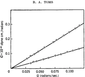
FIG. 9. Relations between G and Ω observed in two experiments at 2 5 ° with a solu- tion in pyridine containing 36.40 gm. of poly (methyl methacrylate) per liter; Inner cylinder I I I , h"-hf = 11.90 cm. (Redrawn b y courtesy Trans. Faraday Soc.)
rate of shear D ( s e c .- 1) and the shear stress r ( d y n e - c m .- 2) are conveniently calculated at r = (rir2)112: they are given b y
D (7)
G"(Q) - g ' ( Q )
2 m ra( A " - A') (8)
and, of course, η' = τ/D. W h e n the liquid is n o n - N e w t o n i a n and the annular g a p is narrow, the same formulas (6) t o (8) give the relations b e t w e e n vis- cosity, rate of shear, and shear stress parametrically, with o n l y a second- order error. I n this case τ has the same physical significance as before, and D is a first-order approximation t o the rate of shear at r = ( r i r2)1 /2 (reckon- ing the annulus v s . diameter ratio as a first-order small q u a n t i t y ) , so long as wall effects are absent.
W a l l effects can b e detected b y plotting η against D (or r ) , as given b y equations (6) t o ( 8 ) , for different annular gaps. A n y appreciable wall effect w o u l d m a k e the curves for different gaps distinct, b u t if wall effects are absent the curves should coincide with o n l y a second-order error.2 2a
T h e results of some steady-state experiments carried out with the appara- tus described in Section I I , 1 are displayed in Figs. 9 and 10. T h e s e d a t a3 5 , 36 refer t o a series of elasticoviscous liquids prepared b y dissolving poly (methyl methacrylate) in pyridine; the solutions contained 2 t o 5 % of p o l y m e r , and
3 5 B . A . T o m s and D . J. Strawbridge, Proc. 2nd Intern. Congr. Rheol. Oxford p . 99 (1953).
3 6 B . A . T o m s and D . J. Strawbridge, Trans. Faraday Soc. 49, 1225 (1953).
100
5
I I I I I I I I o i l
Ι Ο "1 10
D t s e c r1)
FIG. 10. Observed relations at 2 5 ° between viscosity and rate of shear in a series of dilute solutions of poly (methyl methacrylate) in pyridine. (Redrawn from Proc.
2nd Intern. Congr. Rheol. b y courtesy of Butterworths Scientific Publications.)
[η] = 43 l i t e r / g m . T h e G against Ω plots in Fig. 9, which refer t o solution 3 of Fig. 10, illustrate the a b o v e m e t h o d of determining r\' and indicate the consistency of t y p i c a l experimental observations. T h e relations d e d u c e d b e - tween l o g η' and l o g D are represented in F i g . 10. I t is seen t h a t the vis- cosity of each liquid was constant (i.e., N e w t o n i a n behavior prevailed) at sufficiently small rates of shear: this fact is i m p o r t a n t (see Section I I , 3 ) , for it means that the b e h a v i o r in steady shear can b e characterized b y a limiting viscosity coefficient η0. ( T h e value i?0 = 4 can b e d e d u c e d from the data of Fig. 9.)
T h e a c c u r a c y of a determination of η must, of course, b e k n o w n . T h e m o s t exact absolute determinations of liquid viscosity y e t m a d e with a coaxial-cylinder apparatus are p r o b a b l y those of L e r o u x ,37 w h o claimed t o h a v e measured the viscosity of water at various temperatures with an error n o t exceeding 1 part in 200. T h i s degree of precision must b e regarded as extraordinary for its achievement necessitated extreme experimental precautions. I n the present c o n t e x t it is interesting t o n o t e that, in testing their coaxial-cylinder elastoviscometer, O l d r o y d , Strawbridge, and T o m s3 2 obtained the mean value q' = 0.128 (standard deviation 0.002) from nine distinct experiments with a N e w t o n i a n liquid for w h i c h the corresponding value η = 0.130 had previously been determined b y means of a standard capillary viscometer. T h e degree of precision thus indicated is adequate for w o r k of an exploratory character.
3 7 P . L e r o u x , Ann. phys. 4, 163 ( 1 9 2 6 ) .
496 Β . Α . T O M S
η (c/s)
FI G . 11. R e l a t i o n s between d and η observed when the outer cylinder of the elasto- viscometer was oscillated w i t h amplitudes 0.01 radian ( # ) and 0.02 radian ( O ) . Experiments at 25° with the p o l y m e r solution referred t o in F i g . 9. (Coincident points are d e n o t e d € ) . ) ( R e d r a w n b y c o u r t e s y Trans. Faraday Soc.)
T h e stability of laminar flow between relatively rotating coaxial cylinders has been investigated b y T a y l o r ;26 the earliest experiments bearing on this matter were those of C o u e t t e .27
3 . EX P E R I M E N T S IN V O L V I N G OS C I L L A T O R Y MO T I O N
Results obtained w h e n the outer cylinder is oscillating uniformly are more difficult t o interpret. T h e elastic properties exhibited b y any particular liquid are measured b y comparing experimental results with appropriate theoretical predictions for a series of idealized liquids characterized b y different elastic constants. Since different m o d e l liquids can be visualized, agreement between t h e o r y and experiment must b e rigorously tested : it is t o b e considered satisfactory o n l y if the deductions from experiments with one inner cylinder and one torsion wire can b e used t o predict correctly the behavior of the same (real) liquid with different cylinders and wires. In order t o illustrate this procedure, w e shall follow the m e t h o d a d o p t e d b y T o m s and S t r a w b r i d g e8 5 , 36 for investigating the elasticity of certain p o l y - mer solutions. T h e theoretical basis of this particular m e t h o d has been ex- p o u n d e d b y O l d r o y d ,38 and its applicability in a real case w a s first d e m o n - strated b y O l d r o y d , Strawbridge, and T o m s .3 2
Oscillatory experiments are carried out with the annular gap completely filled with liquid. T h e outer cylinder of the elastoviscometer is oscillated with a fixed small amplitude (e.g., 0.01 rad.) at different frequencies, and the amplitude of oscillation of the inner cylinder, with a suitable torsion wire in position, is observed as a function of frequency. T h e results of such an experiment are represented by plotting defined as the ratio of the
3 8 J. G . O l d r o y d , Quart. J. Mech. Appl. Math. 4, 271 (1951).
amplitudes of the inner and outer cylinders, against the frequency η measured in cycles per second. T h e amplitude of the outer cylinder must be small enough for the observed relationship between û and η t o be (very nearly) independent of the absolute value of the amplitude (Fig. 1 1 ) . Several (n, # ) curves corresponding t o different inner cylinders and wires are obtained for each individual liquid (Fig. 1 3 ) .
Predicted (n, # ) curves appropriate t o each experimental setup are o b - tained b y considering a m o d e l elasticoviscous liquid whose behavior in os- cillatory shearing m o t i o n at small amplitudes is characterized b y three constants, a coefficient of viscosity η0, a relaxation time λ ι , and a retarda- tion time λ2. A linear relation between the shear stress r, the rate of shear D, and their rates of change r, D is assumed:
r + λιτ = m(D + λ2Ζ>). ( 9 )
T h e solution of equation (9) required in calculating &(n) at different fre- quencies, with selected values of 770, λ ι , and λ2, has been given b y Old- r o y d .38 T h e calculation of (η, &) curves is a considerable task, even w h e n 770 can b e assumed constant (cf. Fig. 14) ; the values of λι and λ2 which give the best agreement between theory and experiment in the case of a single inner cylinder and torsion wire can b e estimated t o within a b o u t 5 % . ( I n their w o r k on p o l y m e r solutions, T o m s and Strawbridge were able t o limit c o m p u t a t i o n b y preparing solutions with selected values of η0 (cf. F i g . 10) : families of predicted (n, # ) curves could then b e constructed ( O l d r o y d3 8) , enabling approximate values of λι and λ2 t o b e d e d u c e d b y interpolation.36 I n making theoretical predictions, the amplitude of oscillation is supposed
FI G . 12. T h e relations b e t w e e n & and η in the case of a N e w t o n i a n l i q u i d (liquid paraffin B . P . ; 2 5 ° ) . ( R e p r o d u c e d from Proc. Phys. Soc. b y kind permission of the P h y s i c a l S o c i e t y ) .
498 Β . A . T O M S
τ 1 Γ
FI G . 13. Observed relations between û and η in the case of a solution of poly- (methyl m e t h a c r y l a t e ) in pyridine for which p = 0.98 g m . / m l . and η0 = 7.9 poises (25°). ( R e p r o d u c e d from Proc. Phys. Soc. b y kind permission of the Physical S o c i e t y . )
t o b e small, so that the ratio of the amplitudes of the inner and outer cylinders is independent of the amplitude, and η0 can b e identified with the viscosity observed in steady rotation at v e r y l o w rates of shear (see Section I I , 2 ) . T h e full length L of the annulus is assumed filled with liquid, and end effects are ignored.
T h e relation (9) represents the behavior of a t y p e of material which in- cludes as particular cases the Maxwellian elasticoviscous liquid ( λ2 = 0 ) and the N e w t o n i a n viscous liquid (λι = 0, λ2 = 0 ) . I t is seen that the re- laxation and retardation times h a v e the physical significance that if the m o t i o n is suddenly stopped, the shear stress d e c a y s as exp ( — t/\i), and if the stress is r e m o v e d the rate of strain d e c a y s as exp ( — Ζ / λ2) .
T h e agreement between theory and experiment in the case of a N e w t o n - ian liquid (liquid paraifin B . P . of density 0.877 g m . / m l . and viscosity 1.76 poises at 2 5 ° ) is illustrated in Fig. 1 2 .32 I n this diagram, typical experi- mental points obtained at 25° using the inner cylinder I I (see T a b l e I ) , with amplitude 0.01 rad. and a torsion wire of restoring constant 2.79 Χ 1 06 d y n e - c m . / r a d . , are shown in relation t o the theoretical curve. Inset in the figure are shown s o m e of the individual experimental points near the peak, on an increased frequency scale, as an indication of consistency. T h e fre- q u e n c y n0 of free oscillation of the wire and inner cylinder is indicated. I t is seen that $(n) attains a m a x i m u m value, w h i c h does n o t exceed unity, at
FIG. 14. T h e predicted relations between û and n in the case of an idealized elasti- co-viscous liquid for which ρ = 0.98 g m . / m l . , η0 = 7.9 poises, λι = 0.065 s e c , λ2 = 0.015 s e c . ( R e p r o d u c e d from Proc. Phys. Soc. b y kind permission of the P h y s i c a l S o c i e t y . )
a frequency almost exactly equal t o no : these are characteristic features of â(n) in the case of an inelastic liquid;35 moreover, the observed peak height â = 1.00 is consistent with 770 > 0.5. T h e agreement appears to justify the neglect of end effects in the theory of small oscillations, as well as to indicate the accuracy achieved in this kind of experiment with the apparatus de- scribed in Section II, 1.
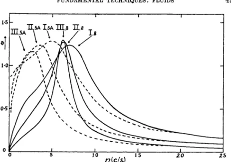
T h e detection and measurement of elasticity in a real liquid are illus- trated b y Figs. 13 and 14.32 T h e experimental results (Fig. 13) refer to a solution of highly polymerized methyl methacrylate in pyridine [(77) = 55 liter/gm.] containing 30.5 g m . of polymer per liter, and with density 0.98 g m . / m l . at 25°. T h e oscillatory experiments were carried out at 25° with the inner cylinders I, II, and I I I (Table I ) and t w o torsion wires (numbers 5A and 8) with restoring constants 0.171 X 10⁶ and 2.79 X 10⁶ dyne- cm./rad.; the amplitude of oscillation of the outer cylinder was 0.01 rad.
throughout (the curves obtained with amplitude 0.02 rad. did not differ significantly from those of Fig. 13).
T h e elasticity of the polymer solution is indicated b y the fact that, in every experiment, & attained a maximum value exceeding unity [charac- teristically, the peak of each observed curve occurs at a frequency greater than no, and when n = n0, # = 1.00 (cf. Fig. 11)]. Non-Newtonian behavior was observed in steady-state experiments, but at very small rates of shear the viscosity was constant and equal t o 7.9 poises (cf., Figs. 9 and 10).
500 Β . Α . T O M S
Assuming η0 = 7.9 and ρ = 0.98, the theoretical curves shown in F i g . 14 were obtained b y determining the values of λι and λ2 which g a v e the best
"fit" for the experimental curve labeled " I I , 8 " (Fig. 13) and then using these same values (viz., λι = 0.065 s e c , λ2 = 0.015 sec.) t o predict curves appropriate t o the other experimental conditions. T h e agreement between theory and experiment appears t o justify the conclusion that, t o a first ap- proximation, the p o l y m e r solution under consideration can b e characterized b y an equation of state of the form ( 9 ) — v a l i d in a simple shearing m o t i o n confined t o sufficiently small rates of shear—with relaxation time 0.065 sec.
and retardation time 0.015 sec. at 2 5 ° .
T h e results of an oscillatory experiment can also b e interpreted t o give the viscosity coefficient 170 : the slope of the (n, # ) curve is measured at the origin, and then appropriate numerical substitutions are m a d e in the equa- tion
*7o
K(r22 - n2)
L
η ^ Ο ηJ (10)
where (as before) η , r2 are the functional radii of the inner and outer cylinders, respectively, Κ is the restoring constant of the torsion wire and L is the length of the annulus.38 T o m s and S t r a w b r i d g e36 h a v e shown that values of 770 determined in this w a y , t h o u g h less accurate, are reasonably consistent with those measured b y the standard m e t h o d (see Section I I , 2 ) .
N o m e n c l a t u r e
a R a d i u s of the b o r e of a p i p e .
c C o n c e n t r a t i o n of solute D A measure of rate of shear Ap Difference of h y d r o s t a t i c
pressure b e t w e e n the ends of a pipe
dp/dz Pressure gradient d o w n a pipe
77' Coefficient of v i s c o s i t y
M fesp/J, w h e r e (1 +
778p) is the relative vis- c o s i t y of a p o l y m e r solu- t i o n
G C o u p l e exerted on the in- ner, or stationary m e m - ber, of t w o r e l a t i v e l y m o v i n g coaxial cylinders
h A distance measured v e r - t i c a l l y on an arbitrary scale
Κ R e s t o r i n g c o n s t a n t of a torsion wire
I L e n g t h of the bore of a pipe
L L e n g t h of the annulus b e - tween coaxial cylinders λι Stress relaxation time λ2 R a t e of strain relaxation
t i m e , or retardation time η F r e q u e n c y of oscillation Ω Angular v e l o c i t y of outer
of t w o r e l a t i v e l y - m o v i n g coaxial cylinders
Q V o l u m e rate of flow t h r o u g h a pipe
Radii of inner and outer of two coaxial cylinders Reynolds number Density
Shear stress
Shear stress at a pipe wall
û R a t i o of amplitudes (in- ner/outer) of t w o c o - axial cylinders in rela- tive oscillatory motion.
f ( ra) Effective velocity of slip per unit shear stress at a
(pipe) wall