Research Article
Real Flight Application of a Monocular Image-Based Aircraft Collision Decision Method
Peter Bauer ,1Antal Hiba ,2and Tamas Zsedrovits 3
1Senior Research Fellow, Systems and Control Laboratory, Institute for Computer Science and Control, Hungarian Academy of Sciences (MTA SZTAKI), H-1111 Budapest, Kende u. 13-17, Hungary
2Junior Research Fellow of Hungarian Academy of Sciences, Computational Optical Sensing and Processing Laboratory, Institute for Computer Science and Control, Hungarian Academy of Sciences (MTA SZTAKI), H-1111 Budapest, Kende u. 13-17, Hungary
3Faculty of Information Technology and Bionics, Pazmany Peter Catholic University, H-1083 Budapest, Prater u. 50/a, Hungary
Correspondence should be addressed to Peter Bauer; bauer.peter@sztaki.mta.hu Received 29 November 2018; Accepted 25 March 2019; Published 16 May 2019 Academic Editor: Jacopo Serafini
Copyright © 2019 Peter Bauer et al. This is an open access article distributed under the Creative Commons Attribution License, which permits unrestricted use, distribution, and reproduction in any medium, provided the original work is properly cited.
This paper considers real flight application of a monocular image-based aircraft collision decision algorithm developed in a previous paper. First, it briefly summarizes the theory based on the previous paper and extends the results with a detailed evaluation of possible special cases. Second, it introduces the UAVs andflight test scenarios together with the camera system and the steps of image processing used inflight testing. A brief analysis about intruder detectability is also provided referencing a more exhaustive work of the authors. The main contribution is the detailed comparison of the image-based estimated collision parameters to the flight trajectory-based ones together with threshold selection for collision decision. Different threshold combinations are evaluated offline, andfinally, realflight decision results based on one of the threshold combinations are also discussed. The paper ends with the setup of future research directions.
1. Introduction
Sense and avoid (S&A) capability is a crucial ability for future unmanned aerial vehicles (UAVs). It is vital to integrate civil- ian and governmental UAVs into the common airspace according to [1] for example. At the highest level of integra- tion, airborne sense and avoid (ABSAA) systems are required to guarantee airspace safety [2].
In thisfield, the most critical question is the case of non- cooperative S&A for which usually complicated multisensor systems (see [3–6] for example) or radar-based solutions (see [7, 8] for example) are developed. However, in the case of small UAVs, the size, weight, and power consumption of the onboard S&A system should be minimal. Monocular vision-based solutions can be cost and weight effective and therefore especially good for small UAVs [9–16]. These sys- tems measure the position (bearing) and size of the intruder aircraft (A/C) camera image without range and physical
intruder size information. This scale ambiguity makes the decision about the possibility of collision (collision means both mid-air collision or near mid-air collision in this article) complicated (see, e.g., [9] where a conservative assumption on intruder’s minimum size is used to make the decision pos- sible but this can lead to false alarms). In another source [13]
where the task is to follow a leader aircraft based on a mon- ocular camera, special maneuvers are required to provide range observability. However, [10] points out that the relative distance of the intruder from the own A/C called the closest point of approach (CPA) well characterizes the possibility of collision together with the time to closest point of approach (TTCPA) and there is a chance to estimate these parameters without any physical intruder information. In the literature, there are several works dealing with TTCPA estimation based on opticflow orfirst-order motion models such as [17–19]. However, it is hard tofind references about the estimation of CPA. For example, [9, 20] target to estimate
Volume 2019, Article ID 7191839, 16 pages https://doi.org/10.1155/2019/7191839
the absolute distance between the A/C the former with the conservative intruder size assumption and the latter by assuming known intruder position and relative velocity.
Consequently, previous efforts of the authors [21–24]
focused on the estimation of TTCPA and CPA values together with the direction of CPA from solely the monocu- lar image parameters. The only restrictive assumption was that the aircraft follows straight flight paths with constant velocities (in these previous works, TTCPA was sometimes referenced as TTC (time to collision)). Formulae to obtain these values with forward looking and even with oblique cameras (see our system in Figure 10) were developed and tested mainly in software in-the-loop (SIL) simulations. The proposed simple solution is based on a least squares (LS) optimal linefit method which well serves real-time execution needs. Error analysis considering image pixelization errors was done in [21].
Our latest work [24] presents the theory of evaluation of the collision situation in three dimensions (3D) estimating TTCPA, horizontal and vertical CPA, and the direction of the horizontal one (βCPA) as it is not necessarily perpendicu- lar to the own A/C forward body axis (see [23] and Figure 2).
The only information lost is the absolute distance between the two A/C; the relative CPA values are determined instead, but this information is appropriate for the decision about the possibility of collision and for the design of an avoidance maneuver. SIL test results are presented, but in-flight testing of such methods is also very important as underlined by [4, 13] for example.
So, the main goal of the current article is to test the developed method on real flight data. That is why after a summary of the theory published before (to make this arti- cle self-contained) and the additional evaluation of special cases, it introduces our real flight test system (A/C and camera system) and applies the derived 3D collision char- acterization on real flight image data. Knowing the sizes and real flight GPS trajectories of the A/C, the obtained camera-based results (TTCPA, CPA, and βCPA) are com- pared to the real data. Finally, suggestions are done for decision threshold selection and real flight decision results based on one possible combination of the thresholds are evaluated. The structure of the paper is as follows. Section 2 briefly summarizes the 3D collision characterization from our previous article [24] by possibly partly reproduc- ing the wording used there. Then it includes detailed eval- uation of the possible special cases. Section 3 introduces our test UAVs and the test scenarios. Section 4 presents our camera system together with the image processing issues. Section 5 summarizes the results of collision situa- tion evaluation in real flight and presents some results about intruder detectability. Finally, Section 6 concludes the paper.
2. Theory of 3D Collision Possibility Decision This section includes a summary of the results obtained in [24] estimating first the horizontal closest point between the A/C and the related vertical distance (P1) and second the vertical closest point and the related horizontal distance
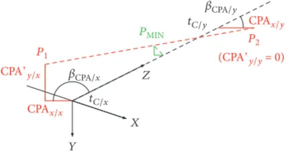
(P2). These points are shown in Figure 1 together with the own aircraft body X,Y,Z coordinate system. The dashed lines symbolize the aircraftflight paths. Note that the order of body coordinate system axes differs from aerospace con- vention to better match camera coordinate system conven- tions of the image processing community.
Considering the interpolation between P1 and P2, the real 3D minimum CPA can be obtained by applying the normalized equivalent of the formula presented in [20]
equation (E4).
The underlying assumption of all of the derivations is that the A/C fly on straight paths with constant velocities.
The collision situation is evaluated relative to the X,Y,Z body coordinate system of the own A/C. TheXC,YC,ZCsep- arate camera coordinate system will be used to characterize camera orientation relative to the body if it is not aligned with the body system (see, e.g., Figure 3).
The horizontal situation in the Z-X plane of the own body coordinate system is shown in Figure 2 denoting also P1, the horizontal closest point. To evaluate this situation (obtain P1), one has to determine tCPA/x, CPAx/x=Xa/R, and βCPA/x. Here, subscriptx denotes that it is a horizon- tal parameter, while the second subscript /x denotes that the parameter is determined by looking for the horizon- tal minimum distance. Xa is the absolute minimum hor- izontal distance while R is the characteristic horizontal intruder size.
In the horizontal plane, the A/C can be modeled as a disc in the same way as in [9]. Considering that the camera of the S&A system can be oblique relative to the body coordinate system (see our system in Figure 10), the disc projection model of the sense and avoid situation is shown in Figure 3.
For a detailed derivation of the disc-based camera projection model for an oblique camera, see [22].
Finally, a system of equations (1) results which includes the modified image parametersSx=Sx cosβ1+ cosβ2 and x=x 1− S2x/ 16f2 . Where x is the horizontal position and Sx is the horizontal size of the intruder image,f is the camera focal length,βCis the camera angle, andβ1and β2 are the view angles of the edges of the intruder image as shown in Figure 3. Allx,Sx,β1,β2are measurable parameters in the image and f, βC are known. The other parameters tCPA/x,CPAx/x, andβCPA/xand the constant intruder relative
P1
PMIN Z
Y
X
P2 tC/y𝛽CPA/y
𝛽CPA/x tC/x
CPAx/y
CPAx/x CPA’y/x
(CPA’y/y = 0)
Figure1: Special points along the 3D A/C trajectories. The dashed line betweenP1andP2is the straight trajectory of the intruder. Note thatβCPA/xis in theX-Zhorizontal plane.
P1 𝛽CPA/x
∼ tCPA/
x ∼ tCPA/x
R
Xa X
Z
Figure2: DefinetCPA/x(TTCPA),CPAx/x=Xa/R, andβCPA/x(intruder: red on the left, own A/C: blue on the right, andP1: the horizontal closest position of the intruder).
ZC
XC 𝛾x
𝛾x 𝛽C 𝛽
Z1
Z2 x1
x2 𝛽1
𝛽2 Z
l
X (X, Z) (XC, ZC)
P f V
r
Figure3: Oblique camera disc projection model.
ZC
YC (Y) 2r
𝛼10 𝛼1 𝛼2
𝛼20 2h
P f
Figure4: Vertical camera ellipse and disc projection models.
3 2
1
Figure5: Three crossing possibilities of the own horizontal plane (red cross: intruder; blue circle: own A/C).
Figure6: Sindy, twin-engine own aircraft.
Figure7: Ultrastick single-engine intruder.
1 2 2
1
Figure8: Almost straight close (1) and far (2) trajectories.
2
2 1
1
Figure9: Oscillating close (1) and far (2) trajectories.
velocitiesVx,Vzare unknown (note thatβCPA/xis shown in Figure 2 and its estimation will be discussed later).
1
Sx = CPAx/x 2
sinβC
f − VxsinβC+VzcosβC 2f R tCPA/x, x
Sx = CPAx/x
2 cosβC− VxcosβC−VzsinβC
2R tCPA/x
1
In the vertical situation, the unknown parameters to obtainP2decrease totCPA/y,CPAy/yas the relative angle will be surely 90°up or down. In the vertical plane, the A/C can- not be modeled as a disc since it is rather similar to an ellipse (length almost equal to the horizontal size of the intruder and height equal to the height of the intruder). However, the pin- hole camera projection model of the ellipse is very compli- cated and later interpolation for the 3D minimum point requires normalization with the same size in the horizontal and vertical CPA. Thus, an extension to the same disc size R= 2r as in the horizontal plane is done considering also the distortion effect dependent on theαangles. This is shown in Figure 4. For details, see [24]. Finally, the extended vertical size in the image plane can be denoted asSy′.
This leads to a similar system of equations as in the horizontal case (see (1)) with modified image parameters Sy′=Sy′ cosα10+ cosα20 and y=y 1− S′2y/ 16f2 .
1
S′y= CPAx 2
sinβC
f − VxsinβC+VzcosβC 2f R tCPA, y
S′y= CPAy′ 2 −Vy
2RtCPA
2
The first equation is exactly the same as that in the horizontal plane so the mean value of the two equations can be considered. Summarizing the results up to now leads to three image parameter-based equations from which the first two characterize the horizontal situation (P1) while the last characterizes the vertical situation (P2):
1 2
1 Sx+ 1
Sy′ = CPAx/x 2
sinβC
f − VxsinβC+VzcosβC 2f R tCPA/x, x
Sx =CPAx/x
2 cosβC−VxcosβC−VzsinβC
2R tCPA/x,
y
Sy′= CPA′y/y 2 −Vy
2RtCPA/y
3 In this system of equations, the unknowns areCPAx/x, CPA′y/y,tCPA/x, andtCPA/y. The terms such as the camera angle βCand focal lengthf, the relative velocitiesVx,Vy,Vz, and the intruder size R are all constant. Considering this and tCPA/x=tC/x−t,tCPA/y=tC/y−t, one gets another form of the equations in (4) and (5). Note thattis the actual varying absolute time while tC/x and tC/y are the constant absolute times when the intruder is closest to the own A/C in the horizontal and vertical planes, respectively.
1 2
1 Sx + 1
Sy′ = sinβC f
CPAx/x
2 −a1tC/x+a1t=c1+a1t, x
Sx = cosβCCPAx/x
2 −a2tC/x+a2t=c2+a2t, 4
Image capture:
USB3 vision camera Processing:
Tegra K1: NVIDIA Kepler GPU + quad- core ARM
2 GB DDR3 memory Data recording:
128 GB SSD (SATA) Communication with control:
USB/RS232 Neutral density filter
IR cutoff filter 2 filters:
Global shutter Resolution: 1280×960 (i)
(iv)(i) (i)
(i)
(ii) (i) (ii)
(iii)(ii)
Figure10: Vision system mounted on Sindy UAV.
y
Sy′ =CPA′y/y
2 −a3tC/y+a3t=c3+a3t 5 The horizontal minimum CPAx/x and the related tC/x can be determined from (4). Fitting LS optimal linear curves to the expressions on the left side with independent variable tgivesa1,a2,c1,c2, and this leads to a system of linear equa- tions for CPAx/x /2andtC/x:
sinβC f −a1
cosβC −a2
CPAx/x 2 tC/x
= c1
c2
6
This system gives a solution forCPAx/xandtC/xconsid- ering the crossing of the body-fixedx-axis by the intruder as the closest point. However, as Figure 2 shows, this is not necessarily the closest point. Perturbing the camera angle to getβ′C/x=βC+ΔβC/x(this means−ΔβC/x virtual rotation of the body system), one can derive the optimal value ofΔ βC/x which gives real minimum CPAx/x and the related tC/x andβCPA/x in the horizontal plane.
sin βC+ΔβC/x
f −a1
cos βC+ΔβC/x −a2
CPAx/x 2 tC/x
= c1
c2
,
minΔβC/x
CPAx/x ⇒tanΔβC/x= −a2 cosβC/f −a1sinβC
−a2 sinβC/f +a1cosβC, βCPA/x=−ΔβC/x+ sign CPAx/x π
2
7
Turning back to the vertical situation from (5), that equation characterizes CPA in the vertical plane. In the case where Vy= 0, a3= 0 and CPA′y/y≠0 can be determined simply from the time average of y/Sy′ values. For this case, the A/C flight paths are parallel in the vertical plane. In the other case,Vy≠0and a3≠0mean thatCPAy/y′ = 0will be the closest vertical point as the trajectories cross each other in the vertical plane. For this case, c3= CPAy/y′ /2 − a3tC/y=−a3tC/y. Doing a line fit to the y/Sy′,t data pairs will give c3 and a3 from which tC/y can be determined:
tC/y=−c3/a3 .
It can be proven that ifVy= 0andCPAy/y′ ≠0, the clos- est horizontal pointP1 will also be the closest 3D point (for details, see [24]). Its coordinates result as follows (where v stands for the vertical parameter and h for the horizontal parameter):
tCMIN=tC/x, tCPAMIN=tCMIN−t, CPAvMIN′ = CPA′y/y, CPAhMIN= CPAx/x, βCPAMIN=βCPA/x
8
In the other case, if Vy≠0, one should determine the vertical position of the intruder (CPA′y/x) in pointP1 while the horizontal position is at tC/x, CPAx/x, and βCPA/x and also determines the horizontal position ofP2while the ver- tical position is attC/yand CPA′y/y= 0.
InP1,CPAy/x′ can be determined from (5) by substituting tC/xintoc3obtained from LS optimal linefit. InP2,CPAx/y and the relatedΔβC/y(and soβCPA/y) values should be deter- mined. This can be done considering the system of equations for the averaged image size and horizontal data from (4) and (7) (β′C/y=βC+ΔβC/y).
sinβ′C/y f −a1
cosβC/y′ −a2
CPAx/y 2 tC/y
= c1
c2
9
AstC/yis known, the system can be reformulated having the known values on the right-hand side:
sin βC+ΔβC/y CPAx/y
2f =a1tC/y+c1=b1, cos βC+ΔβC/y CPAx/y
2 =a2tC/y+c2=b2,
10
where the unknowns are CPAx/y and ΔβC/y. Depending on the values ofb1andb2, there can be different solutions. For details, see [24].
Summarizing the developments, one has two points, P1with parametersCPAx/x,βCPA/x, CPA′y/x,tC/x andP2with CPAx/y,βCPA/y, CPAy/y,tC/yas shown in Figure 1.
The coordinates of pointsP1andP2in the body coordi- nate system (X,Y,Zin Figure 1) so result as follows:
P1
Z1= cosβCPA/xCPAx/x, X1= sinβCPA/xCPAx/x, Y1= CPA′y/x,
11
P2
Z2= cosβCPA/yCPAx/y, X2= sinβCPA/yCPAx/y, Y2= 0
12
An interpolated point betweenP1 and P2 can be repre- sented as follows. Note that the given representation with
the tM parameter makes extrapolation before P1 or after P2 also possible.
ZM=Z1+tM Z2−Z1
tC/y−tC/x =Z1+tMΔZ, XM=X1+tM X2−X1
tC/y−tC/x =X1+tMΔX, YM=Y1+tM
Y2−Y1
tC/y−tC/x =Y1+tMΔY
13
Minimizing the 3D distanceD= Z2M+X2M+Y2M gives tM=− Z1ΔZ+X1ΔX+Y1ΔY/ΔZ2+ΔX2+ΔY2 which is exactly the same as thetCPAvalue calculated in [20] (E4) from absolute trajectory parameters, but here, this is an extension of the formula relative to CPA distances. Consider- ing this result, the time of minimum 3D distance and the related relative CPA values in case the A/C trajectories cross the vertical plane can be determined as follows:
tCMIN=tC/x+tM, tCPAMIN=tCMIN−t, CPAvMIN′ =YM, CPAhMIN= X2M+Z2M, tanβCPAMIN=XM
ZM
14
Finally, CPAvMIN related to the H real vertical size (Syreal vertical image size) of the intruder should be calcu- lated fromCPAvMIN′ (calculated from the extendedSy′vertical image size) considering the ratio kbetween horizontal and vertical sizes and taking its time averagek:
k=H R ≈Sy
Sx, CPAvMIN= Ya
H = 1
kCPAvMIN′
15
The approximation in (15) shows that there can be differ- ent distortions ofSyandSx. A method to correct this is pro- posed in [24] and so k should be calculated based on the corrected values.
2.1. Possible Special Cases. After developing the formulae, they should be examined for special cases to avoid any singu- larity in the calculations. Sources such as [25, 26] point out that a critical special case in A/C collision avoidance is the case of collision with zero miss distance where the intruder A/C will be steady in the pilot’s view. For this case, it will be also steady in the camera system’s view and so this can be a problematic case in image-based S&A also. Considering an oblique camera setup, three special cases can occur in the horizontal plane:
Case 1. Xa= 0, Vx= 0, andβC≠0which means a head-on scenario with zero miss distance and an oblique observer camera.
Case 2.Xa= 0,Vx≠0, and βC= 0which means a crossing scenario with zero miss distance and a forward-looking camera.
Case 3. Xa= 0, Vx= 0, andβC= 0which means a head-on scenario with zero miss distance and a forward-looking camera.
These cases are examined in the sequel considering also the possible vertical situation and thatCPAx/x= 0in all cases becauseXa= 0.
2.1.1. Case 1 (Vx= 0,βC≠0). In this case, the horizontal equations from (3) and (4) degrade to
1 2
1 Sx + 1
Sy′ =−VzcosβC
2f R tCPA/x=−a1tC/x+a1t=c1+a1t, x
Sx =Vz sinβC
2R tCPA/x=−a2tC/x+a2t=c2+a2t 16 This shows that the LS optimal line fits can be done flawlessly and so a1,a2,c1,c2 are obtained witha1=Vzcos βC/ 2f R and a2=VzsinβC/ 2R theoretical values.
Substituting these into the expression ofΔβC/xin (7) gives
tanΔβC/x= VzsinβCcosβC/ 2f R − VzsinβCcosβC/ 2f R Vzsin2βC/2f R/ 2f R + Vzcos2βC/ 2f R
= 0
17 This givesΔβC/x= 0and the following form of the equa- tion system to be solved from (7) (considering alsoc1=−a1
tC/xandc2=−a2tC/xtheoretical values):
sinβC f −a1
cosβC −a2
U= −a1tC/x
−a2tC/x 18 It is easy to derive the solution as
U= 0
tC/x , 19
which givesCPAx/x= 0andtC/x. ConsideringβCPA/xfrom (7), one getsβCPA/x= 0as−ΔβC/x= 0andsign CPAx/x= 0 = 0.
Considering now the possible vertical situations ifVy= 0, it is eitherCPA′y/y= const≠0orCPA′y/y= 0if the A/Cfly in the same horizontal plane y= 0→y= 0 . The calculation of both of them is straightforward from the mean value of
y/Sy′and will be the same in the further two cases also. The only vertical scenario left is the crossing of the own horizon- tal plane by the intruder with CPA′y/y= 0 and Vy≠0. For this case, after determining tC/y, CPAx/y should be deter- mined from (10) considering that b1=a1 tC/y−tC/x , b2= a2 tC/y−tC/x . The relation oftC/yandtC/xgives three possi- ble cases shown in Figure 5.
The vertical crossing can be earlier than the horizontal one (in front of the own A/C) (tC/y<tC/x; no. 1 in Figure 5), and it can be at the same time (tC/y=tC/x; no. 2 in Figure 5) or later (behind the own A/C) (tC/y>tC/x; no. 3 in Figure 5).
In the second case,b1= 0,b2= 0, andCPAx/y= 0according to [24]. In the other cases, b1≠0 and so the formula from [24] can be used to determineΔβC/y
tanΔβC/y= cosβC− b2/ b1f sinβC
sinβC+ b2/ b1f cosβC 20 Substituting the theoretical values ofa1,a2intob1,b2and the latter into (20) equation gives
tanΔβC/y= cosβC+ tanβCsinβC
sinβC−tanβCcosβC =∞ 21 This gives ΔβC/y=π/2 and CPAx/y can be calculated from this. Finally, βCPA/y=−π/2 + sign CPAx/y π/2 which is either 0 or −π radian giving the expected in-front or behind crossing.
Finally, the calculation of the 3D minimum distance with interpolation should be examined for the special case. The final parameters are βCPA/x= 0, CPAx/x= 0, CPAy/x′ ≠0, βCPA/y= 0or−π, andCPAx/y≠0(CPA′y/xcan be determined from (5) knowingc3andtC/x). This gives the coordinates of points P1 and P2 as Z1= 0,X1= 0,Y1= CPA′y/x and Z2= ± CPAx/y,X2= 0,Y2= 0from (11) and (12), respectively. Con- sidering the interpolation, the only singular case istC/y=tC/x where the horizontal and vertical crossing coincides and this gives immediately the 3D minimum. Otherwise, there is no problem in calculating the minimizingtM parameter withΔ Z≠0,ΔX= 0, andΔY≠0.
2.1.2. Case 2 (Vx≠0,βC= 0). In this case, the LS optimal line fits can also be done flawlessly and so a1,a2,c1,c2
are obtained witha1=Vz/ 2f R and a2=Vx/ 2R theoret- ical values. Substituting these into the expression of ΔβC/x in (7) gives
tanΔβC/x=− Vx/ 2f R
Vz/ 2f R =−Vx
Vz ≠0 22 This is the calculation formula that resulted from a forward-looking camera in [23] so it is natural to get this result. Now, the equation system to be solved from
(7) results as (considering also βC= 0,c1=−a1tC/x,c2=−a2
tC/x)
sinΔβC/x f −a1
cosΔβC/x −a2
U= −a1tC/x
−a2tC/x , 23 giving again
U= 0
tC/x , 24
which gives CPAx/x= 0 and tC/x. ConsideringβCPA/x from (7), one gets βCPA/x=−ΔβC/x= 0 as sign CPAx/x= 0 = 0.
This is only a theoretical value because CPAx/x= 0and has no definite direction.
Considering the only special vertical case withCPA′y/y= 0 andVy≠0, no. 1 and no. 3 cases withb1≠0give the following:
tanΔβC/y= Vz
Vx 25
From this,ΔβC/y=−π/2−β∞v andΔβCPA/y=π/2 +β∞v + sign CPAx/y π/2.β∞v = constis the view angle of the intruder from the own aircraft if Xa= 0and can be obtained from tanβ∞v =−Vx/−Vz(for details, see [23]). Sofinally, the cross- ing of horizontal plane will be along the line characterized by β∞v in this direction or in the opposite direction.
Regarding the calculation of the 3D minimum distance with interpolation, the final parameters here result as βCPA/x≠0, CPAx/x= 0, CPA′y/x≠0, βCPA/y=β∞v or β∞v +π, and CPAx/y≠0. This gives the coordinates of pointsP1and P2 asZ1= 0,X1= 0,Y1=CPAy/x′ andZ2≠0,X2≠0,Y2= 0 from (11) and (12), respectively. Considering the interpola- tion, the only singular case istC/y=tC/xwhere the horizontal and vertical crossing coincides and this gives immediately the 3D minimum. Otherwise, there is no problem in calcu- lating the minimizing tM parameter with ΔZ≠0, ΔX≠0, andΔY≠0.
2.1.3. Case 3 (Vx= 0,βC= 0).In this case, (16) further sim- plifies and the LS optimal line fits will give a1,c1,a2= 0, c2= 0byfitting the second line on a constant zero parameter.
This leads to
tanΔβC/x= 0 a1
= 0, 26
which givesΔβC/x= 0and soβCPA/x= 0. Thefirst equation in (7) simplifies to
0 −a1
1 0 U= −a1tC/x
0 , 27
giving again
U= 0
tC/x , 28
which givesCPAx/x= 0andtC/x. Considering the only special vertical case withCPA′y/y= 0andVy≠0, no. 1 and no. 3 cases withb1≠0,b2= 0give the following:
tanΔβC/y=1
0 =∞ 29
This givesΔβC/y=π/2as in Case 1 andβCPA/y=−π/2 + sign CPAx/y π/2 which is either 0 or −πradian giving in- front (of the own A/C) or behind crossing.
Regarding the calculation of the 3D minimum distance with interpolation, thefinal parameters here have the same result as in Case 1, βCPA/x= 0, CPAx/x= 0, CPAy/x′ ≠0, βCPA/y= 0orπ, andCPAx/y≠0. From this point, the same deduction can be done.
2.1.4. Summary about Special Cases.All of these derivations show that original formulae (4), (5), (7), (10), and (13) can be well applied in these special cases without any modifica- tion. This is underlined by the Monte-Carlo test run in [24]
where Case 2 and Case 3 scenarios are included both with specialtC/y=tC/x and crossing in-front and behind vertical setups and there were no singularity or any problem with the formulae. Of course, for real data, the theoretical values will be corrupted by noise but considering multiple measure- ments will smoothen this out in some extent.
After developing a method to determine the 3D mini- mum distance (relative to intruder size) between two A/C in an encounter scenario, it should be tested in detail. Refer- ence [24] presented promising results of a SIL Monte-Carlo simulation campaign. The current article presents results based on realflight data. This will be done in Section 5 after introducing the test A/C and scenarios and the used camera system and image processing methods.
3. Test Aircraft and Scenarios
Realflight tests are conducted with two UAVs on an airfield near Budapest (Hungary). The own A/C is a large 3.5 m wingspan, about 10-12 kg twin-engine A/C called Sindy (see Figure 6) developed in our institute (SZTAKI) to carry large payloads such as the sense and avoid system (for details and building instructions (as it is an open source project), see [27]).
The intruder A/C is a small 1.27 m wingspan 1.5-2 kg single-engine A/C which is the E-flite Ultra Stick 25e (see Figure 7). The small size of the intruder makes detection and decision about the collision difficult as the numerical results will show. However, as the S&A system works accept- ably in this scenario which is close to the worst case, the sys- tem will perform even better as the conditions get better.
Both A/C are equipped withIMU + GPS + Pitot tubeand an air pressure sensor and an MPC5200 onboard microcon- troller with attitude estimation and autopilot algorithms.
Waypoint or trajectory tracking (constructed from straight lines and arcs) is also possible with them. For the details of the sense and avoid hardware/software system on Sindy, see Section 4.
The S&A test flights were conducted in October/- November 2016 byflying the two A/C on parallel, horizontal, straight flight paths with 15 m (close flight) and 30 m (far flight) horizontal side distances between them. The flying on nonparallel paths would be much more complicated as [28] points out. The own A/C air relative velocity was set to be 20 m/s while that of the intruder was 17 m/s giving 37 m/s closing speed in the ideal case. During thefirst set of testflights, the avoidance was deactivated to make in detail offline algorithm evaluation possible. Note that if an avoid- ance maneuver is done, the own A/C trajectory is modified and it is impossible to evaluate the closest point as if there was no avoidance. In the second set of testflights, avoidance in the horizontal plane (only consideringP1parameters) was activated and maximum bank turn avoidance maneuvers were done when required. Setup of a safety altitude separa- tion (15 m for close test and 10 m for far test) was mandatory in the first set and advised in the second (that is why only horizontal avoidance was applied). Depending on the initial conditions, actual wind disturbance, and turbulence, the tracking of the straight line can show some oscillatory behav- iour which can compromise camera data and the precision of the S&A algorithm. A close test case and a far test case with almost straight trajectories are shown in Figure 8 while oscil- lating ones are shown in Figure 9.
4. Camera System
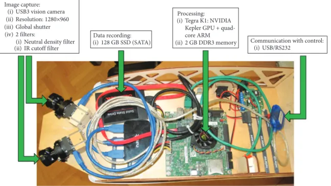
Figure 10 presents the camera system hardware and the main characteristics of the components. The system includes two Basler dcA 1280 cameras which have a 65.4° field of view (FOV). They are setup withβC= ±30°camera angles which givesfinally±62.7°total FOV. This is in good agreement with the±60°angle range suggested for pilots to scan for intruders in [25]. The NVIDIA Jetson TK1 board is responsible for image processing and decision making. This hardware is capable of processing and saving the 2x HD monochrome video input at about 8 fps. Communication between the auto- pilot and camera system is minimal. The autopilot sends the orientation of the aircraft while the camera system sends only an evasion alert and suggested avoidance direction.
4.1. Image Processing.Recent papers onflying object detec- tion and tracking utilize deep neural networks [29]. The accuracy of these methods is impressive; however, these tech- niques have too large computational complexity for onboard real-time computation. The evolution of new hardware and research on more efficient neural network design will lead to robust flying object detection in the future; however, now, different methods were applied. Here, we introduce our approach which was used in the realflight tests. The task of detectingflying objects in images is easier being against the sky than against the ground. All objects which are not a cloud or the sun and have no connection to the ground areflying objects and can be determined on a single frame. Against
the ground, we could detect and track objects which are moving compared to the background considering multiple frames for the detection. Our method now focused on detec- tion against sky background with the following three stages:
sky-ground separation, blob detection against sky back- ground, and false objectfiltering.
4.1.1. Sky-Ground Separation.We perform sky-ground sepa- ration by horizon detection. The basic method was published in [30]. The main idea is to calculate a horizon line based on the orientation of the aircraft and the known relative orienta- tion of the camera. This horizon line is not accurate enough, because of the small airframe deformations during maneu- vers and calibration errors, but this makes it very easy to cre- ate a good sky-ground separation (Figure 11).
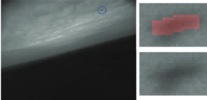
4.1.2. Blob Detection against Sky Background. Algorithm 1 is an example preprocessing method to extract candidate objects. Candidate objects include real flying objects with false positives (cloud edges and so forth). A successfully detected aircraft and its enlarged and shaded region can be seen in Figure 12. Thus, an object filter is applied to classify flying objects.
4.1.3. Object Filter.Most of the false sky objects can be elim- inated efficiently with simplefiltering rules. The main rule defines threshold on the pixel variance in the neighborhood of the object mask which eliminates cloud edges. These hand- crafted rules were enough for successfulflight tests in good conditions (homogeneous clear or cloudy background);
however, in some cases, we had still too many false positive objects which can cause false evasions. With the next- generation faster NVIDIA TX1-based camera system, classi- fication of candidate objects could be performed with a small convolutional neural network.
4.1.4. Parameters to the Collision Decision.Finally, the hori- zontal and vertical centroid positions (x,y) and object sizes (Sx,Sy) are obtained after detection. From these parameters, a rectangle is created which is egomotion compensated (see [10]). This means rotation from the camera to the body, from the body to the trajectory, and then from the trajectory to the camera coordinate system. The trajectory system is a body system rotated to be parallel to the straightflight trajectory.
This way, the intruder direction is evaluated relative to the trajectory direction irrespective of the current orientation of the own aircraft. After egomotion compensation, (x,y) and (Sx,Sy) are recalculated and then passed to the algorithm in Section 2.
5. Real Flight Test Results
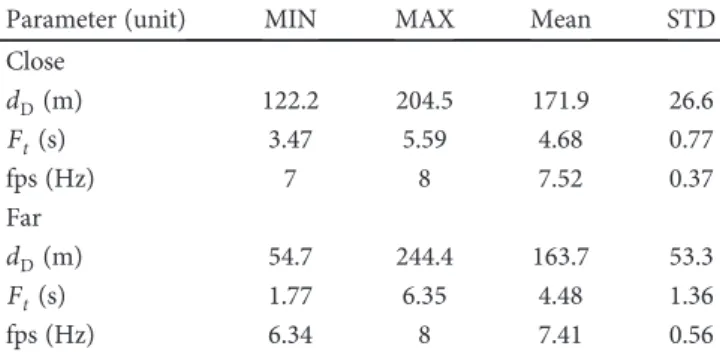
From thefirst set offlight tests (without avoidance), several important parameters can be evaluated such as the detection distancedDof the intruder, the time frameFtto make a deci- sion and execute avoidance (from time of detection to time of CPA), and the fps (frames per second) rate of the camera system. 8 close and 9 far encounters were flown, and data synchronization between the two A/C was done considering the global GPS UTC (coordinated universal time) time stamps. Note that the GPS frequency is 5 Hz so the time res- olution of data is 0.2 s. The minimum, maximum, and mean values and the standard deviations (STD) of the above parameters are summarized in Table 1 for the close and far encounters.
Figure11: Horizon detection in the image with radial distortion. The blue line represents the horizon calculated from orientation, and the red line corresponds to the improved sky-ground separation.
1. Step:5 × 5erosion (grayscale) 2. Step:13 × 13Gaussianfilter
3. Step: adaptive threshold: pixelthreshold = 9 × 9 average−2 4. Step:5 × 5erosion (binary)
5. Step:5 × 5dilation (binary).
Algorithm1. Preprocessing.
Figure12: Aircraft detection. The red region in the enlarged image shows the object mask from preprocessing.
Considering the data in the table, thefpsof the camera system with onboard image processing and decision making is between 6.3 and 8 Hz with a mean of about 7.5 Hz. This is about half or less than the 15-20 Hz in [12], but in that paper, they did ground-based calculations with a laptop computer while we applied an onboard system carriable by the Sindy A/C and making the S&A system autonomous. Future hard- ware developments can easily increase this rate.
The detection distance is between 122 and 204 m in the close scenarios while it is between 55 and 244 m in the far ones. Here, detection means that the tracking of the intruder by the camera system is stable and continuous from that point. The mean values are 172 and 164 m, respectively.
Regarding the means, these results outperform the 60-70 m detection distance of a 1.6 m wingspan A/C in [12] (note that our intruder wingspan is only 1.27 m). The very small (55 m) detection distance in the far scenarios is an outlier (the mean 164 m is close to the close scenario 172 m mean), and we could not figure out what caused it. Theflight trajectories were good, and so, the intruder could not move out of the camera system FOV so possibly some image blur or distor- tion could cause it.
The time frame to make a decision is 3.47-5.59 s for close and 1.77 6.35 s for far scenarios because of the same reasons as fordD. The means are 4.7 s and 4.5 s, respectively, which do not provide too much time to make a decision and execute avoidance. Considering the later selected 3 s TTCPA thresh- old which provides 2 to 4 s real time until the closest point and the required 2-3 s convergence time of our algorithm, it would be better to have 6-7 s from observation until the clos- est point. That is why such a small A/C as an Ultrastick air- craft is a critical case which makes avoidance with large safety distance impossible. On the contrary, our article [31]
points out that for general aviation A/C (7 m and above wingspan), the time from detection to the closest point is at least 7 seconds which can provide enough time for successful avoidance. It is also worth noting that approximately 10 s [25] and 12.5 s [26] are the required time for a human pilot to detect, identify, and avoid an intruder which is outper- formed by the 6-7 s time of our system. From dD and Ft, the average closing speed of the A/C can be calculated which results between 31 and 40 m/s with a mean of about 36.5 m/s close to the theoretical 37 m/s value.
5.1. More Details about Intruder Detectability.An exhaustive study about the detectability of intruders with different
camera systems, sizes, and speed is published in [31]. Some of the observations deduced there are repeated here to put our previous observations into context. At first, it is worth to mention that the detectability of an object by a camera mainly depends on the sensor area occupied by the image on the sensor. This area can be directly related to the object pixels through the so-called pixel pitch parameter. Another possibility can be to use the subtended angle of the object, but this suffers from distortion by approaching the edges of the image plane. Sofinally, the covered area (size) was con- sidered in [31]. Table 2 repeats the considered camera parameters from there.
Our camera in the flight tests is the Basler dcA 1280.
Considering the R= 1 27 m size of the Ultrastick aircraft and the Z= 164 m average detection distance makes it possible to calculate the average detectable size in pixels as S= f⋅R/Z ≈8 px. Considering the pixel pitch, this gives about 30μm size on the sensor. The MIN sizes for the other cameras in the table were calculated from this value. The minimum and maximum detection distances for several aircraft sizes were calculated considering the worst (dcA 1280) and best (acA 2040) cameras as shown in Table 3.
For the Ultrastick A/C, the worst distance (159 m) is close to our mean detection distance (164 m) which is not surpris- ing as we calculated the parameters from this. Our maximum detection distance (244 m) is very close to the best result (245 m) which means that even the worst camera can give superior results in some cases but, of course, using higher- resolution cameras can improve the results. These tests in [31] and the pinhole projection formulaZ=f ⋅R/Sshow that the camera should have a large focal length (f) and small detectable occupied sensor areaS. That is why acA 2040 out- performed acA 2500 becauseSis much larger and the focal length is almost the same in the latter case.
The time to the closest point of approach at the time of A/C detection strongly depends on the speed of the own and intruder A/C. A thorough evaluation of this problem is done in [31].
5.2. Results and Thresholding with Flight Test Data.Thefirst set offlights (without avoidance) makes it possible to com- pare S&A system estimates with real physical data. Real 2D (only horizontal) and 3D closest points were calculated from GPS data for all close and far encounters. Then the calcu- lated distances were normalized by intruder wingspan b= R= 1 27 mand heightH= 0 33 m(the real height/size ratio thus results as k= 0 33/1 27 = 0 26) to finally get tCPAMIN, CPAvMIN′ , CPAhMIN,βCPAMIN. As the A/C fly on horizontal paths, there is no crossing in the vertical plane and so the verticalCPAvMIN′ ≠0and the 2D horizontal CPA is the same as the that of the 3D. So, it is enough to compare the esti- mated and real 3D results.
The S&A algorithm was run offline for all close and far encounters, and the estimates are compared to the A/C trajectory-based real values in Figures 13–19. The LS linefits were done on 7 data points to consider about 1 s data (fps is about 7.5).
Table1: Basic essential parameters of S&A system application.
Parameter (unit) MIN MAX Mean STD
Close
dD(m) 122.2 204.5 171.9 26.6
Ft(s) 3.47 5.59 4.68 0.77
fps(Hz) 7 8 7.52 0.37
Far
dD(m) 54.7 244.4 163.7 53.3
Ft(s) 1.77 6.35 4.48 1.36
fps(Hz) 6.34 8 7.41 0.56
Figure 13 shows the estimatedtCPAMINon the horizontal axis and the error realtCPAMIN−estimatedtCPAMIN on the vertical axis. Note thattCPAMINchanges withtin every time
step as the intruder approaches the own A/C. These tCPAMIN time series values are plotted together with their instantaneous errors in the figure. If the error is positive, there is more time to CPA than estimated. This representa- tion is advantageous to consider the possibilities for decision threshold (THS) selection. Thefigure shows thatfirst (when the estimatedtCPAMINis large), the TTCPA is overestimated and then, as the intruder approaches, it is underestimated.
Table 4 summarizes the observations.
According to the table, an estimatedtCPAMINTHS of 3 s will result in a decision between 2 and 4 s real time before
3 2 1 0
0 1 2 3 4 5
−1
−2
−3
Estimated tCPAMIN (s) tCPAMIN estimation errors
tCPAMIN error (s)
Figure13: Estimation errors of 3D TTCPA (red x: close encounters;
blue circle: far encounters).
0 5 10 15 20 25
Estimated CPAhMIN (−) CPAhMIN estimation errors 20
10 0
−10
−20 CPAhMIN error (−)
Figure14: Estimation errors of 3D horizontal CPA (red x: close encounters; blue circle: far encounters).
0 0.5 1 1.5 2 2.5 3 3.5
Estimated tCPAMIN (s) tCPAMIN-CPAhMIN nomogram 60
50 40 30 20 Estimated CPAhMIN 10
Figure 15: TTCPA-horizontal CPA nomogram (red x: close encounters; blue circle: far encounters).
Table2: Camera data.
Type Basler dcA 1280 Basler acA 1440 Basler acA 2040 Basler acA 2500
Pixel count (Mp) 1.2 1.6 3 5
Camera resolution 1280 × 960 1440 × 1080 2048 × 1536 2592 × 1944
Pixel pitch (μm) 3.75 3.45 3.45 2.2
Focal lengthf (px) 997.3 1217.4 1739.1 1818.2
View angle (°) 65.4 61.2 61 71
MIN sizeS(px) 8 9 9 14
Table3: Camera system detectability results.
AC type Size (m) Worst range (m) Best range (m)
Boeing 747 68 8477 13140
Boeing C-17 52 6482 10048
Embraer ERJ-145 25 3117 4830
MQ-9 Reaper 15.6 1945 3014
MQ-8 Fire Scout 7.7 960 1488
Ultrastick 1.27 159 245
0 0.5 1 1.5 2 2.5 3 3.5
Estimated tCPAMIN (s) tCPAMIN-CPA'vMIN (R relative) nomogram 40
35 30 25 20 15 10 5 0 Estimated CPA'vMIN
Figure 16: TTCPA-vertical CPA (Rrelative) nomogram (red x:
vertical far encounters; blue circle: vertical close encounters).