1
Numerical Analysis of VVER-440/213 Concrete Biological Shield
Yuliia Khmurovskaa, Petr Štemberka*, Tamás Feketeb, Tapani Eurajokic
a Czech Technical University in Prague, Faculty of Civil Engineering, Department of Concrete and Masonry Structures, Thákurova 7, 166 29 Prague 6, Czech Republic
b MTA Centre for Energy Research, 1121 Budapest, Konkoly Thege M. út 29-33, Hungary
c Fortum Power and Heat Oy, Keilalahdentie 2-4, P.O.Box 100, FI-00048 FORTUM, Espoo, Finland
* Corresponding author, E-mail: stemberk@fsv.cvut.cz Abstract
The numerical approach for the coupled damage-creep modeling of concrete biological shield, which combines the current and the past knowledge regarding the effects of irradiation and temperature on concrete with the real measured and calculated neutron fluence and temperature distribution for VVER-440/213 reactors, is described in detail in this study. The proposed approach takes into account the real structural geometry as well as the real neutron fluence and temperature distribution and the latest knowledge about the effect of irradiation and temperature on concrete strength and stiffness. The radiation induced volumetric expansion and the thermal expansion of concrete are modeled. According to the results of the numerical simulation, the analyzed structure reaches critical damage within the time interval from 10.00 to 35.25 years of normal operation.
The damage of the concrete biological shield of the VVER reactor will not affect the load-bearing function of the containment building, since the biological shield is self-bearing. The shielding properties of the biological shield may be reduced due to the appearance of the radial cracks, however, the concrete wall, which is situated right behind the biological shield, will ensure the necessary shielding. Therefore, the concrete biological shield of the VVER reactors can be considered as sacrificial structure and can be damaged without significant consequences. However, this study implies the importance of capability to predict the behavior of those PWR reactor biological shields which serve both the load-bearing and shielding purposes.
Keywords: Biological shield; Concrete; Creep; Damage; Neutron fluence; Temperature; VVER 1. Introduction
This study focuses on the numerical analysis of the structural response of a real nuclear power plant (NPP) biological shield which takes into account the real irradiation and temperature conditions. Three examples of NPPs, besides others of the same reactor type, can be mentioned which may benefit from this study.
Dukovany Nuclear Power Plant is situated in the Czech Republic and consists of four units of VVER-440/213 reactors. The operation of the oldest Unit 1 started in 1985 year. The design operation life of this type of reactors is thirty years and expired in 2015. Recently, (in 2016-2017), the operation license of all four units was extended for an indefinite period with the next planned inspection in 2025. The situation in Hungarian Paks Nuclear Power Plant is similar. It also consists of four units of VVER-440/213 reactors. The Unit 1 is under the operation since 1982. During 2012 and 2017, all the units were granted a license-extension for additional 20 years of operation.
2
Consequently, their total permitted operation time is 50 years. Loviisa Nuclear Power Plant in Finland consists of two units of VVER 440/213 reactors. The Unit 1 is under operation since 1977 and similarly to the above described Dukovany and Paks nuclear power plants it has an operation license till 2027, which corresponds to 50 operational years. The Unit 2 of the Loviisa NPP also has an operation license for 50 years, i.e. to the end of year 2030. As a difference from the Dukovany and Paks NPPs, at Loviisa NPP 36 outermost fuel assemblies are replaced with “shield elements” therefore the neutron flux and operation temperature are lower.
There are two significant factors which lead to development of this study. Firstly, there is no precedent of such a long-term radiation exposure to concrete which would be well documented and with the neutron flux similar to that in operating NPPs. Secondly, there is no possibility to investigate the real-scale structural elements under long-term irradiation conditions, mainly due to safety restrictions and cost. Therefore, the only possible way to predict the behavior of concrete biological shield is to use available data from accelerated tests on small-scale concrete specimens obtained in test reactors and to extrapolate these data to real scale by numerical simulation.
This paper then presents a numerical approach to predict the VVER-440/213 concrete biological shield behavior under long-term irradiation, which also considers the temperature and creep effects. The presented numerical approach utilizes the latest research results related to concrete degradation under irradiation and operation temperature as well as the real experimental measurements and numerical estimations of the neutron flux and temperatures generated by VVER-440/213 reactors during their normal operation. The ultimate goal of this study is to assess the possible mechanical response and the state of the concrete biological shield under normal power plant operational condition.
2. Problem description 2.1. Geometry
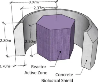
The concrete biological shield of VVER-440/213 reactor is a self-bearing cylindrical wall with the inner radius of 2.37 m, the outer radius of 3.07 m and the height of 2.8 m. The upper 0.6 m of the cylindrical wall is truncated from the outer side upward at an angle of 45 degrees as shown in Fig. 1.
Fig. 1. Geometry of concrete biological shield of VVER-440/213 reactor.
3
Fig. 2. Neutron flux distribution: (a) height neutron flux distribution and neutron flux attenuation, (b) azimuthal neutron flux distribution.
2.2.Neutron flux
In order to obtain the neutron flux distribution on the inner surface of the concrete biological shield, detailed 3D neutron transport calculations were performed for the volume residing between the outer boundary layer of the active core and the inner boundary layer of the concrete biological shield, using the MCNP4C code with the appropriate Evaluated Nuclear Data File cross-section libraries. The neutron flux distributions on the core-volume interface were generated by detailed 3D reactor-physics calculations for the core. The Monte Carlo N-Particle neutron transport calculations for the given volume take into account the real 3D structure of the core baffle, the downcomer, the reactor pressure vessel wall and the cavity, so the neutron flux and neutron fluence results for the inner boundary layer of the concrete biological shield are adequate. The obtained neutron flux with the maximum value of 4.95·1010 n/cm2/s for the fast neutrons (>0.1 MeV) corresponds to the direct flux measurements.
Fig. 3. Neutron fluence distribution on inner surface of concrete biological shield over time.
4
The 60-degree symmetry of the azimuthal flux distribution was assumed due to the hexagonal shape of VVER reactor active core, (Košťál et al., 2016; Tóth et al., 2006). The height and the azimuthal neutron flux distribution are shown schematically in Fig. 2(a) and Fig. 2(b), respectively.
The accumulated neutron fluence at different time intervals was calculated as the sum of the flux, with the realistic assumption of 300 operational days per year. The total neutron fluence on the inner surface of the biological shield is shown in Fig. 3.
The neutron flux over the thickness of concrete decreases due to the attenuation which, as the first and crude estimation, is defined by the exponential neutron attenuation law
surf Rd
f d f e , (1)
where f(d) is the neutron flux at a given depth under the inner surface of the biological shield, fsurf
is the neutron flux on the inner surface of the biological shield, ΣR = 0.191 1/cm is the neutron removal cross section which corresponds to Portland concrete and is in accordance with (Esselman and Bruck, 2013) and d is the depth under the inner surface of the biological shield given in cm, (Khmurovska and Štemberk, 2018; Willam et al., 2013). The neutron flux attenuation effect is schematically shown in Fig. 2(a).
In this way, the neutron flux and, subsequently, the neutron fluence can by defined at any point on the inner surface as well as under the inner surface of the biological shield at any given time instant.
2.3. Temperature
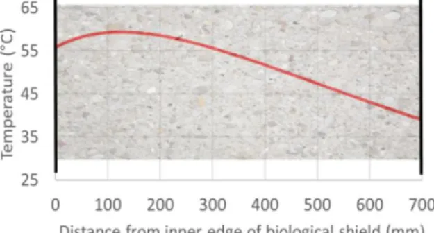
The temperature distribution was obtained from a 1D numerical analysis of Loviisa Nuclear Power Plant biological shield and represents the “full” core, thus corresponding to the temperature at the Dukovany and Paks NPPs and slightly overestimating that at the Loviisa NPP. The 1D temperature field is used with the assumption of insignificant temperature gradient in azimuthal and vertical directions. The calculated temperature field is in accordance with the measured reference values at Dukovany and Paks NPPs and is shown in Fig. 4. It should be noted that the highest temperature is located inside the biological shield and not on the surface due to the consideration of gamma radiation heating.
Fig. 4. Temperature distribution in concrete biological shield in operation.
2.4. Concrete degradation caused by irradiation
According to the current and past research the properties of concrete change due to neutron irradiation, while gamma irradiation does not affect concrete properties significantly, (Hilsdorf et al., 1978; Field et al., 2015; Maruyama et al., 2018). Neutron irradiation causes the so-called metamictization (amorphization in some literature) of mineral crystal structures. Since the cement paste consists mostly of the amorphous calcium silicate hydrate gel, it is believed that the neutron
5
irradiation affects the cement paste only slightly (Kontani et al., 2010). Metamictization of aggregates composed of crystalline minerals causes the so-called radiation induced volumetric expansion (RIVE) (Hilsdorf et al., 1978; Field et al., 2015; Kontani et al., 2010). The RIVE depends on the crystal structure of minerals which constitute the aggregates. The random distribution of the expanding aggregates in concrete mass causes crack formations and, consequently, reduction in concrete strength and stiffness, (Hilsdorf et al., 1978; Field et al., 2015;
Maruyama et al., 2017).
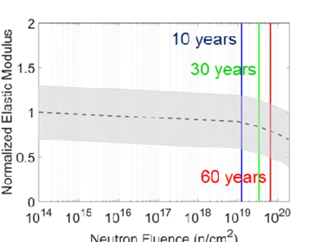
Fig. 5. Concrete elastic modulus degradation caused by irradiation.
Fig. 6. Concrete compressive strength degradation caused by irradiation.
6
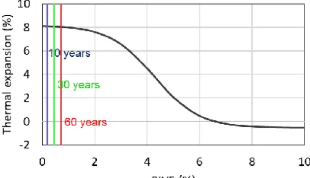
Fig. 7. Concrete tensile strength degradation caused by irradiation.
Since the aggregate type varies from study to study, the degradation of concrete properties are expressed as a normalized value at a given neutron fluence, (Field et al., 2015), see Figs. 5-7, where the gray area denotes 90 % confidence interval of the experimental measurements, the black dashed curve indicates an average trend and the blue, green and red lines denotes maximum neutron fluence on the surface of the VVER-440/213 biological shield after 10, 30 and 60 years of operation, respectively. The best fitting of the average trends can be expressed analytically as follows (Le Pape, 2015)
0 exp a
irr irr
RE E E b , a4.025 10 1, b4.073 10 22cm2/n, (2)
0 exp a
irr irr
fc c c
R f f b , a1.582, b7.253 10 21cm2/n, (3)
0 exp a
irr irr
ft t t
R f f b , a4.364 10 1, b8.649 10 21cm2/n, (4) where R is the reduction factor, E, fc, ftare the elastic modulus, the compressive and the tensile strength, respectively, the superscript 0 indicates the initial value and the superscript irr denotes the value after irradiation at a given fluence, Φ is the neutron fluence, a and b are fitted material constants according to (Le Pape, 2015).
The radiation induced elastic modulus degradation is shown in Fig. 5 and the average trend which is used in the modeling, is expressed by Eq. 2. Similarly, the radiation induced compression and tension strength degradation is shown in Figs. 6 and 7 and is expressed by Eqs. 3 and 4, respectively.
2.5. Concrete degradation caused by operation temperature
The temperature, at which an NPP normally operates, along with the gamma radiation heating can cause non-uniform thermal expansion of aggregates and cement paste and the subsequent degradation of concrete. Heating up to 120°C affects slightly concrete properties, (Lee et al., 2009).
Elevated-temperature induced elastic modulus degradation under stressed condition shows a linear trend and can be expressed as, (Willam et al., 2009; Nielsen et al., 2004),
0 1 0.1
temp temp
RE E E ,
T T 0
100, 0 10, (5)where T is the specimen temperature in °C and the superscript temp denotes the value of specimens under thermal load at given temperature, while the superscript 0 indicates the initial value.
The change of the concrete compressive strength under elevated temperature shows a parabolic reduction and can be expressed as follows, (Nielsen et al., 2004; Willam et al., 2009),
0 2
1 0.016
temp temp
fc c c
R f f , 0 7.9. (6)
The concrete tensile strength degradation is expressed by a piecewise linear function, (Phan et al., 1996; Willam et al., 2009),
0 1
temp temp
ft t t
R f f , 20 C T 50C,
0 1 0.1356
temp temp
ft t t
R f f , 0 6.4, (7)
0 0.2
temp temp
ft t t
R f f , 640 C T 800C.
2.6. RIVE
Due to the fact that the concrete biological shield is a self-bearing structure, i.e. it supports only itself, the RIVE of aggregates becomes the primary acting load. The RIVE depends on aggregate
7
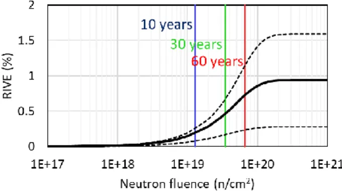
composition, as was mentioned above. All existing data regarding the RIVE are collected in (Hilsdorf et al., 1978; Field et al., 2015; Kontani et al., 2010; Maruyama et al., 2017). Since the data regarding serpentinite and barite, either of which were used as the coarse aggregate in the concrete in Dukovany, Paks and Loviisa NPPs, are limited, the data available in (Le Pape, 2015) for structural concrete were used in present modeling and were expressed by the so-called Zubov function, (Zubov and Ivanov, 1966),
max max
RIVE e 1
k ke
, (8)
where εRIVE is the RIVE strain, εmax = 0.936 % is the maximum RIVE strain, k = 0.968 % and δ = 3.092·10-20 cm2/n are material parameters according to (Le Pape, 2015).
Fig. 8. RIVE of structural concrete.
Eq. 8 is visualized in Fig. 8 with the black full line, while the black dashed lines denote the minimum and the maximum RIVE which cover the 90 % confidence interval of the existing experiments, which are explained in detail in (Le Pape, 2015). The blue, green and red lines in Fig.
8 denote the maximum fluence on the inner surface of the biological shield after 10, 30 and 60 years of operation, respectively.
2.7. Thermal expansion
Another significant load which affects the concrete biological shield is the thermal expansion.
The experimental data regarding the effect of irradiation on the coefficient of thermal expansion is limited. The data for α-quartz aggregates (Le Pape et al., 2016) are used in the presented numerical approach as the most comprehensive of the available data and are expressed by
0 1
1 1
1
RIVE C RIVE L C aggr
e e
, (9)
where αaggr is the coefficient of thermal expansion of α-quartz aggregates, α0 = -0.52·10-6 1/°C is the coefficient of thermal expansion of α-quartz after phase transformation due to elevated temperature, α1 = 8.63·10-6 1/°C, εC = 0.85 % and εL = 4.27 % are fitted material parameters according to (Le Pape et al., 2016).
Fig. 9 shows the change of the coefficient of thermal expansion of α-quartz as a function of RIVE with indication of the maximum RIVE on the surface of the biological shield after 10, 30 and 60 years in blue, green and red, respectively.
The total coefficient of thermal expansion of concrete, which considered its dependence on RIVE, was calculated as
8
aggr aggr cem cem
V V
, (10)
where αcem is the coefficient of thermal expansion of cement independent of irradiation, Vaggr and Vcem are the volume fractions of aggregate and cement paste in concrete mixture, respectively.
It should be noted that the empirical curve defined by Eq. 9 is valid for quartz only, however, the change is insignificant (see Fig. 9) and rather it shows the possibilities of the code.
Fig. 9. Coefficient of thermal expansion of irradiated α-quartz.
3. Numerical approach and verification
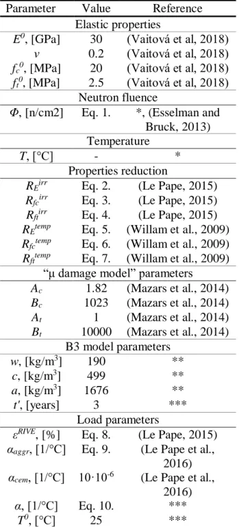
In order to carry out the numerical simulation of the biological shield, the nonlinear finite element method code was written in MATLAB. The basic parameters which are used in the analysis are summarized in Table 1, where ν is Poisson's ratio, Ac, Bc, At, Bt are the damage model constants which define the shape of the stress-strain diagram, w, c and a are water, cement and aggregate (fine and coarse) content in kg in 1 m3 of concrete, respectively, t' is the age of concrete at the beginning of loading in years.
The biological shield was modeled in 3D using the 12-degrees of freedom linear tetrahedrons.
The problem was considered as quasi-static.
When the degradation of the concrete properties due to irradiation and operation temperature was determined, it was possible to define the concrete properties at any point of biological shield at any time by
^ irr temp 0
E E
E R R E , (11)
^ irr temp 0
c fc fc c
f R R f , (12)
^ irr temp 0
t ft ft t
f R R f , (13)
where the superscript ^ denotes the value after irradiation at operation temperature.
Mazars’ “μ damage model”, which is based on Mazars damage model (Mazars and Pijaudier- Cabot, 1989; Mazars et al., 2014), was used in the presented numerical approach. The Mazars damage model can be used for radiation induced damage analysis and shows acceptable results according to (Le Pape, 2015). The isotropic mechanical damage Dmech is calculated using the “μ damage model” as
(1 )
mech mech
RE D , (14)
0
irr temp mech
E E E
ER R R E , (15)
where REmech is the reduction factor due to mechanical damage. The damage surface then can be defined after specification of the reduced elastic modulus, the compressive and tensile strength.
Eq. 15 is mathematically equal to
9 (1 ) 0,
1 (1 irr)(1 temp)(1 mech),
E D E
D D D D
(16)
presented in (Willam et al., 2013;Nechnech et al., 2002), where (1 – Dirr ) = REirr and (1 – Dtemp )
= REtemp represent the isotropic damage due to irradiation and the operation temperature effect, respectively. The following approach assumes irradiation-induced damage and mechanical damage independent, however, it may be overly conservative.
In the study presented by Gray (1971), the influence of neutron irradiation on concrete creep was investigated and it appeared to be insignificant, nevertheless, the final conclusion is difficult to draw from this experiment. According to Denisov et al. (2012), the creep of the irradiated samples is approximately seven times higher in comparison with the control samples, however, an increase in the creep is explained by the high temperature (240 °C) which accompanied irradiation in the test reactor. The research presented by Dubrovskii et al. (2010) also concludes that the increase in creep is caused by the elevated temperature only. Therefore, the effect of irradiation on concrete creep may be neglected and the commonly accepted B3 model (Bažant and Jirásek, 2018) can be used. Since the steel liner, which covers concrete biological shield, prevents concrete drying, only the basic creep was taken into account with the assumption of constant relative humidity in the concrete body. Then, according to the B3 model, the basic creep of concrete depends on the concrete composition, the concrete stiffness, the stress level, the load duration and the age of concrete structure.
The interaction between the damage model and the creep model was carried out by coupling the models using the staggered algorithm with the following constitutive equation
( tot temp irr cr)
E , (17)
where σ is the stresses, E is the elastic modulus defined by Eq. 15, εtot is the total strain, εtemp is the thermal strain, εirr is the linear strain due to the RIVE and εcr is the creep strain defined as follows
3
temp RIVE irr
cr cr
T
J
, (18)
where α is the coefficient of thermal expansion defined by Eq. 10, ΔT is the temperature change, εRIVE is the RIVE strain defined by Eq. 8, Jcr is the creep compliance defined by B3 model (Bažant and Jirásek, 2018).
Since the mechanical damage may grow even under constant stresses, the strain, which drives the evolution of mechanical damage, is calculated as follows
(1 )
tot temp irr cr
, (19) where ω is a material parameter, which, as the crude estimation, is equal to 0.2 according to (Bažant and Jirásek, 2018; Mazzotti and Savoia, 2003).
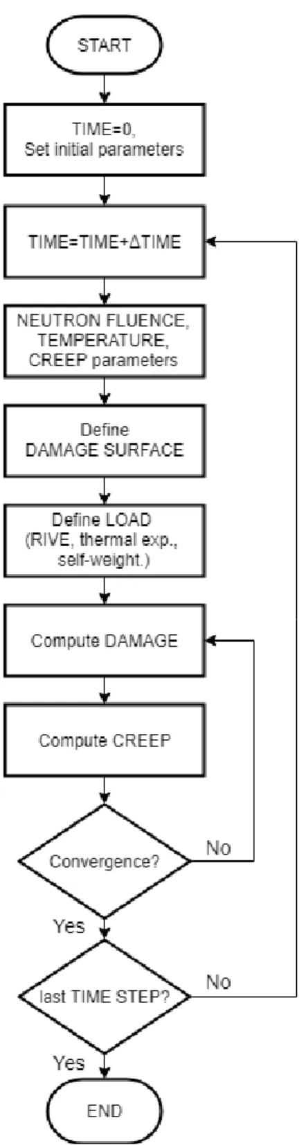
The system of nonlinear equations was solved using the force-controlled modified Newton- Raphson method in each time step with the time increment equal to a quarter of a year. The system of nonlinear equations converges when the sum of squares of the residual divided by the sum of squares of the applied force is less than 1·10-6. The iteration process was then stopped when the convergence was achieved. Then, the solver proceeded to the next time step. The concise flowchart of the analysis is shown in Fig. 10.
10
Table 1 Material properties used in modeling Parameter Value Reference
Elastic properties
E0, [GPa] 30 (Vaitová et al, 2018) ν 0.2 (Vaitová et al, 2018) fc0, [MPa] 20 (Vaitová et al, 2018) ft0, [MPa] 2.5 (Vaitová et al, 2018)
Neutron fluence
Φ, [n/cm2] Eq. 1. *, (Esselman and Bruck, 2013) Temperature
T, [°C] - *
Properties reduction
REirr Eq. 2. (Le Pape, 2015) Rfcirr Eq. 3. (Le Pape, 2015) Rftirr Eq. 4. (Le Pape, 2015) REtemp Eq. 5. (Willam et al., 2009) Rfctemp Eq. 6. (Willam et al., 2009) Rfttemp Eq. 7. (Willam et al., 2009)
“μ damage model” parameters
Ac 1.82 (Mazars et al., 2014) Bc 1023 (Mazars et al., 2014) At 1 (Mazars et al., 2014) Bt 10000 (Mazars et al., 2014)
B3 model parameters w, [kg/m3] 190 **
c, [kg/m3] 499 **
a, [kg/m3] 1676 **
t', [years] 3 ***
Load parameters
εRIVE, [%] Eq. 8. (Le Pape, 2015) αaggr, [1/°C] Eq. 9. (Le Pape et al.,
2016) αcem, [1/°C] 10·10-6 (Le Pape et al.,
2016) α, [1/°C] Eq. 10. ***
T0, [°C] 25 ***
* measured and calculated environmental conditions during the normal operation of NPP
** real structural concrete mixture composition for Dukovany NPP
*** estimated parameters
11
Fig. 10. Concise flowchart of analysis.
12
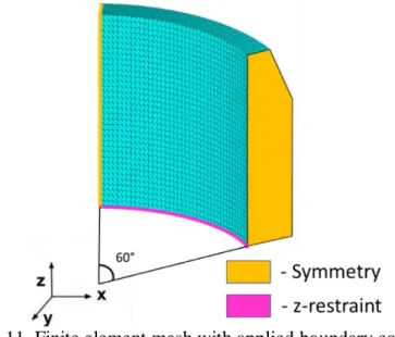
The 60-degree segment of the biological shield was analyzed with the assumption of the flux symmetry due to the 60-degree symmetry geometry of the reactor active zone (see Fig. 2). The regular finite element mesh with the maximum element size of 7 cm and the applied boundary conditions are shown in Fig. 11.
Fig. 11. Finite element mesh with applied boundary conditions.
The developed finite element code was verified with available related experimental data. The verification was performed according to the experiment presented in (Kommendant et al. 1979) where the concrete for NPPs was studied. The concrete cylinders with the radius of 76.2 mm and the height of 406.4 mm made of concrete with the compressive strength of 45 MPa were insulated and subjected to a sustained load of 14.48 MPa, which does not cause damage to the samples, and 29.3 MPa, which causes damage of the samples. The loading started at the sample age of 28 days.
The concrete mixture was composed of 449 kg/m3 of cement, 170 kg/m3 of water and 1810 kg/m3 of aggregates (fine and coarse). The strain calculated using the developed code shows good correlation with the experimental data, see Fig. 12 for both undamaged and damaged concrete.
Fig. 12. Verification example.
13 4. Results and discussion
According to the numerical simulation, the concrete biological shield is already severely damaged after the simulated 12.75 years of normal operation, when the solver was not able to find an equilibrium of the analyzed structuresince the force-controlled Newton-Raphson method was used in the developed code. Then, the 12.75 years indicate the end of the theoretical structural integrity time of the analyzed biological shield in this study.
Fig. 13. Displacement of biological shield after 12.75 years of normal operation (Magnification = 5000) (a) with creep and temperature, (b) without creep and temperature.
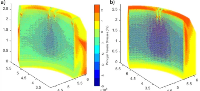
Fig. 14. Principal tensile stresses in biological shield after 12.75 years of normal operation (a) with creep and temperature, (b) without creep and temperature.
The corresponding displacements, the principal tensile stresses and the damage of the biological shield in the case which takes into account creep and temperature effect are shown in Figs. 13(a), 14(a) and 15(a), while the displacements, the principal tensile stresses and the damage which were calculated without creep and temperature effect are shown in Figs. 13(b), 14(b) and 15(b). The structural integrity time for these two cases remained unchanged and equal to 12.75 years due to
14
the negative effect of temperature change (increase of stresses) and positive effect of creep (stresses redistribution). However, the displacements, principal stresses distribution and the damage varied, see Figs. 13-15.
Fig. 15. Damage in biological shield after 12.75 years of normal operation (a) with creep and temperature, (b) without creep and temperature.
The compressive stresses in Fig. 14, which are much lower than the compressive strength, appear in the zone which is affected by the neutrons, but the upper part and the outer surface of the analyzed structure is under significant tension due to the structural response. It can be seen that the principal tensile stresses achieve their limit, which implies the occurrence of cracks and, as shown in Fig. 15, the deep radial cracks develop from the upper part of outer surface of the analyzed structure and propagate inward.
The effect of creep on the concrete biological shield plays an extremely important role in its structural performance. According to the presented numerical simulation, the theoretical structural integrity time of the analyzed structure decreases to 2.00 years from initial 12.75 years in the analysis without creep but with temperature because of the concentration of the huge thermal stresses near the supports due to the rapid heating. This is in accordance with (Giorla et al., 2017), which also shows the damage delay due to the creep. It should be noted that when the creep is not considered, the damage is localized in the support area, which will not result in reduction of the load-bearing capacity or the shielding properties of the analyzed self-bearing structure, but rather it indicates changes in the damage pattern. Therefore, since the creep not only slows down the damage evolution but also changes the damage pattern, it is recommended to perform the coupled creep-damage analysis of the concrete biological shield in 3D due to the highly non-uniform load distribution. The above also emphasizes the serious need to conduct an experimental investigation on the effect of radiation on the concrete creep in order to clarify the radiation induced creep mechanism. In further analysis the case with the creep and temperature effect which is shown in Figs. 13(a), 14(a) and 15(a) is taken in consideration.
In order to estimate the creep sensitivity, these parameters were selected: concrete composition, the age of concrete at loading and the ω parameter (Bažant and Jirásek, 2018; Mazzotti and Savoia, 2003). Firstly, the mixture with the composition presented in (Kommendant et al. 1979) was used
15
in the analysis. The strength and the elastic modulus remained unchanged and as a result the structural integrity time reduced to 12.00 years from 12.75 years. Secondly, the age of concrete at loading was changed to one year from the realistic three years and as a result the structural integrity time increased to 15.50 years for concrete mixture presented in Table 1 and to 15.00 years for concrete mixture presented in (Kommendant et al. 1979). Thirdly, the ω parameter varied from 0 to 0.35 and as a result the structural integrity time varied within the limit of ±5 %. Therefore, the reasonable alteration of the creep parameters affects the rate of damage development insignificantly.
The important aspect in these results is that with consideration of the RIVE lower limit (see Fig. 8.), the calculated structural integrity time of the concrete biological shield increases to 35.25 years from the initially obtained 12.75 years, which corresponds to the maximum fluence of 4.02·1019 n/cm2. Similarly, with consideration of the RIVE upper limit, the structural integrity time decreases to 10.00 years, which corresponds to the maximum fluence of 1.28·1019 n/cm2. The obtained neutron fluence value is in accordance with the limit value for the fast neutrons proposed by United States Nuclear Regulatory Committee, (US Nuclear Regulatory Commission, 2016), and the new reference value proposed in Japan for the fast neutron fluence, (Maruyama et al., 2017), which is equal to 1·1019 n/cm2. Here it should be noted that the biological shield of some PWR reactors which are used in the USA and Japan is not only a shielding structure but also a load-bearing structure, (Rosseel et al., 2016). Therefore, its damage or displacement may result in serious consequences. On the other hand, the biological shield of the VVER reactors is a shielding structure only, and thus, its damage or displacement will not affect the containment structural performance or the designed reactor position.
It should be also noted that the neutron attenuation due to the steel sheet liner of the thickness of 1.2 cm, which covers the concrete biological shield, was not taken into account in the presented simulation, which is a conservative assumption. According to the past and current research, the neutron removal cross section of different steel varies from 0.1586 to 0.2103, (Kassab et al., 2015;
El-Khameesy et al., 2015). Then, even with more undervalued estimation when the neutron removal cross section of steel is equal to that of iron, 0.1576 1/cm (Snyder and Neufeld, 1957;
Lamarsh and Baratta 2001), the maximum flux reduces to 2.48·1010 n/cm2/s from the originally considered maximum value of 4.95·1010 n/cm2/s and the critical damage of the biological shield is reached after 15.25 years of operation instead of the calculated 12.75 years, when the mean RIVE curve is used.
It should be also noted that the analysis uses theoretical values of the concrete stiffness and the strengths in tension and compression. However, the real values can by much higher. For example, (Altynbaev et al., 2016) provides the mean value of concrete compressive strength during the construction of Unit 1 of Balakovo Nuclear Power Plant in 1980 of 40 MPa and the minimum value of 30 MPa with the design value of 20 MPa. If the real minimum value of the initial compressive strength of 30 MPa with the corresponding initial tensile strength of 2.9 MPa and the modulus of elasticity of 32 GPa are used in the analysis, the critical damage of concrete biological shield occurs after 18.00 years of operation instead of 15.25 years. Moreover, if the real mean value of the initial compressive strength of 40 MPa with the corresponding initial tensile strength of 3.5 MPa and the modulus of elasticity of 35 GPa are used, the critical damage occurs after 18.75 years of the normal operation. According to this parametric study, with consideration of the mean RIVE curve, the biological shield will be damaged critically during the design operational time anyway. However, it should be stated at this point that the damage to the analyzed biological shield does not affect the normal NPP operation. As can be seen in Fig. 16, the truncated top of the
16
biological shield is supplemented with an antisymmetric concrete wedge, which is also covered in a steel liner and which can attenuate the penetrating neutrons. The calculated result can be seen in Fig. 16 (a) when it is expected that the neutron will be fully attenuated by the biological shield and the supplementary concrete wedge. Nevertheless, hypothetically, when the crack pattern lets the neutrons go through the supplementary concrete wedge, the load-bearing concrete wall may be affected, however, the affected area will be very small, or even negligibly small when the thickness of the load-bearing concrete wall is considered, see Fig. 16 (b).
Fig. 16. Redistribution of neutron flux and analysis of potential consequences (a) crack in concrete biological shield, (b) crack in concrete wedge.
The temperature, at which the accelerated irradiation tests are carried out, varies from 10 to 550
°C, according to (Field et al., 2015; Willam et al., 2013). The low temperature can speed up the RIVE significantly, while the high temperature results in the RIVE delay due to the thermal healing, (Bykov et al. 1981, Le Pape et al., 2016). That means that either the RIVE has to be a function of temperature as proposed in (Maruyama et al., 2017) for α-quartz or only the data which were obtained under the temperature prevalent in the concrete biological shield (about 40 to 60 °C for VVER-440/213, see Fig. 4) should be used in numerical simulations. The reason for this limitation is that the high temperature, under which some of the accelerated irradiation tests were carried out, leads to additional inaccuracy, when the concrete samples can be damaged by the irradiation as well as the elevated temperature during the accelerated irradiation tests.
5. Conclusions
This paper describes in detail the numerical approach to the coupled damage-creep analysis of VVER-440/213 concrete biological shield, which combines existing hypotheses and experimental data on irradiation and temperature effects on concrete with the real flux and temperature measurements and calculations.
According to the result of the presented numerical simulation, the radiation induced volumetric expansion of aggregates (RIVE) is the primary factor that affects the structural performance of concrete biological shield. Nevertheless, it is emphasized that the effect of RIVE should be considered together with the temperature and creep effects in order to obtain realistic results.
17
The obtained results indicate that the concrete biological shield of VVER-440/213 reactor may be damaged critically as early as after 10 years of the NPP normal operation, when its shielding property is partially compromised. However, this fact does not affect the containment building or the reactor pressure vessel design performance as the biological shield is self-bearing statically- isolated structure. The partial reduction of shielding properties of the biological shield is compensated by the supplementing antisymmetric concrete wedge, which attenuates the permeating neutrons. Only hypothetically, as the material parameters were underestimated in the presented study, the neutrons may affect the load-bearing concrete wall, but the effect would be negligible with respect to the thickness of the load-bearing concrete wall, which supports the reactor pressure vessel. However, this result evidences the necessity to be able to predict the behavior of the biological shield of those PWR reactors which combine both the load-bearing and shielding function. In order to eliminate the uncertainties related to material properties and environmental condition, additional experiments have to be performed, such as related to barite and serpentinite RIVE or direct measurements of temperature fields during the entire operation cycle.
Acknowledgements
This work was supported by Ministry of Education, Youth and Sports of Czech Republic, project 8F17002, which is gratefully acknowledged. This work was a part of the project No.
127102 that has been implemented with the support provided from the National Research, Development and Innovation Fund of Hungary, financed under the NN_17 V4-Korea funding scheme, which is gratefully acknowledged.
References
Altynbaev, A., Poliakova, P., Iakobson, M., Chernobaeva, A., Erak, D., Zhurko, D., Zverev, I., 2016. Prolongation of NPP service life. III Annual Scientific and Practical Conference
"AtomStroyStandard 2016". http://atomsro.ru/wp-
content/uploads/file/0PORTAL/AtomStroyStandart_2016/Poliakova_2016_AS.pdf (accessed 04 January 2019) (in Russian).
Bažant, Z., Jirásek, M., 2018. Creep and Hygrothermal Effects in Concrete Structures (Vol. 225).
Springer Netherlands. https://doi.org/10.1007/978-94-024-1138-6.
Bykov, V., Denisov, A., Dubrovskii, V., Korenevskii, V., Krivokoneva, G., Muzalevskii, L., 1981.
Effect of irradiation temperature on the radiation expansion of quartz Soviet At. Energ. 51(3), 593-595. https://doi.org/10.1007/bf01135758.
Denisov, A., Dubrovskii, V., Solovyov, V., 2012. Radiation resistance of mineral and polymer construction materials. Moscow: ZAO Publishing House “MEI” (In Russian).
Dubrovskii, V., Lavdanskii, P., Engovatov, I., 2010. Construction of nuclear power plants.
Moscow: Publishing Association of Civil Ingeeniring Universities (In Russian).
The Attenuation Capability of Selected Steel Alloys for Nuclear Reactor Applications. J. Adv.
Phys. 11(3), 3139-3145. https://doi.org/10.24297/jap.v11i3.485.
Esselman, T., Bruck, P., 2013. Expected Condition of Concrete at age 80 of Reactor Operation.
Technical Report A13276-R-001. Lucius Pitkins, Inc., 36 Main Street, Amesbury, MA 01913.
https://doi.org/10.2172/1468217.
18
Field, K., Remec, I., Le Pape, Y., 2015. Radiation effects on concrete for nuclear powerplants, Part I: Quantification of radiation exposure and radiation effects. Nucl. Eng. Des. 282, 126–
143, http://dx.doi.org/10.1016/j.nucengdes.2014.10.003.
Giorla, A., Le Pape, Y., Dunant, C., 2017. Computing creep-damage interactions in irradiated concrete. J. Nanomech. Micromech. 7(2), 04017001. https://doi.org/10.1061/(asce)nm.2153- 5477.0000118.
Gray, B., 1971. The effect of reactor radiation on cement and concrete. In: Proceedings of an Information Exchange Meeting on ‘Results of Concrete Irradiation Programmes’. Commission des Communautés Européennes, Brussels, Belgium, 55–69.
Hilsdorf, H., Kropp, J., Koch, H., 1978. The Effects of Nuclear Radiation on the Mechan-ical Properties of Concrete. Spec. Publ. Am. Concr. Inst. 55, 223–254.
Kassab, M., El-Kameesy, S., Eissa, M., 2015. A Study of Neutron and Gamma-Ray Interaction Properties with Cobalt-Free Highly Chromium Maraging Steel. J. Mod. Phys. 6(11), 1526- 1532. https://doi.org/10.4236/jmp.2015.611156.
Khmurovska, Y., Štemberk, P., 2018. FEM and RBSM Numerical Analysis of Concrete Wall under Long-term Exposure to Neutron Irradiation. In: Proceedings of the 12th International PhD Symposium in Civil Engineering, Prague, Czech Republic.
Kommendant, G.J., Polivka, M., Pirtz, D., 1976. Study of concrete properties for prestressed concrete reactor vessels, Final Report No. UCSESM 76-3, Department of Civil Engineering, University of California, Berkeley.
Kontani, O., Ichikawa, Y., Ishizawa, A., Takizawa, M., Sato, O., 2010. Irradiation Effects on Concrete Structures. In: Proceedings of International Symposium on the Ageing Management
& Maintenance of Nuclear Power Plants, Mitsubishi Research Institute. 173-182.
https://doi.org/10.1002/9781118536254.ch27.
Košťál, M., Cvachovec, F., Jánský, B., Rypar, V., Juříček, V., Harutyunyan, D., Schulc, M., Milčák, J., Novák, E., Zaritsky, S., 2016. Neutron deep penetration through reactor pressure vessel and biological concrete shield of VVER-1000 Mock-Up in LR-0 reactor. Ann. Nucl.
Energy 94, 672–683. http://doi.org/10.1016/j.anucene.2016.04.014.
Lamarsh, J., Baratta, A., 2001. Introduction to nuclear engineering (Vol. 3). Prentice Hall. Upper Saddle River, NJ, USA.
Lee, J., Xi, Y., Willam, K., Jung, Y., 2009. A multiscale model for modulus of elasticity of concrete
at high temperatures. Cem. Concr. Res. 39, 754-762.
https://doi.org/10.1016/j.cemconres.2009.05.008.
Le Pape, Y., 2015. Structural effects of radiation-induced volumetric expansion on unreinforced concrete biological shields. Nucl. Eng. Des. 295, 534-548.
https://doi.org/10.1016/j.nucengdes.2015.09.018.
Le Pape, Y., Giorla, A., Sanahuja, J., 2016. Combined effects of temperature and irradiation on concrete damage. J. Adv. Concr. Technol. 14(3), 70-86. https://doi.org/10.3151/jact.14.70.
Maruyama, I., Kontani, O., Takizawa, M., Sawada, S., Ishikawa, S., Yasukouchi, J., Sato, O., Etoh, J., Igari, T., 2017. Development of soundness assessment procedure for concrete members affected by neutron and gamma-ray irradiation. J. Adv. Concr. Technol. 15, 440–523.
https://doi.org/10.3151/jact.15.440.
Maruyama, I., Ishikawa, S., Yasukouchi, J., Sawada, S., Kurihara, R., Takizawa, M., Kontani, O., 2018. Impact of gamma-ray irradiation on hardened white Portland cement pastes exposed to atmosphere. Cem. Concr. Res. 108, 59-71. https://doi.org/10.1016/j.cemconres.2018.03.005.
19
Mazars, J., Pijaudier-Cabot, G., 1989. Continuum damage theory—application to concrete. J Eng Mech ASCE. 115(2), 345–365. https://doi.org/10.1061/(asce)0733-9399(1989)115:2(345).
Mazars, J., Hamon, F., Grange, S., 2014. A new 3D damage model for concrete under monotonic, cyclic and dynamic loadings. Mater. Struct. 48(11), 3779-3793.
https://doi.org/10.1617/s11527-014-0439-8.
Mazzotti, C., Savoia, M., 2003. Nonlinear creep damage model for concrete under uniaxial compression. J. Eng. Mech., 129 (9), 1065–1075. https://doi.org/10.1061/(asce)0733- 9399(2003)129:9(1065).
Nechnech, W., Meftah, F., Reynouard, J., 2002. An elasto-plastic damage model forplain concrete subjected to high temperature. Eng. Struct. 24, 587–611. https://doi.org/10.1016/s0141- 0296(01)00125-0.
Nielsen, C. V., Pearce, C. J., Bicanic, N., 2004. Improved phenomenological modelling of transient thermal strains for concrete at high temperatures. Comput. Concr. 1(2), 189-209.
https://doi.org/10.12989/cac.2004.1.2.189.
Phan, L., 1996. Fire performance of high-strength concrete: A report of the state-of-the art, Building and Fire Research Laboratory, National Institute of Standards and Technology, NISTIR 5934. https://doi.org/10.6028/nist.ir.5934.
Rosseel, T. M., Maruyama, I., Le Pape, Y., Kontani, O., Giorla, A. B., Remec, I., Wall, J.J., Sircar, M., Andrade, C., Ordonez, M., 2016. Review of the Current State of Knowledge on the Effects of Radiation on Concrete. J. Adv. Concr. Technol. 14(7), 368-383.
https://doi.org/10.3151/jact.14.368.
Snyder, W, Neufeld, J., 1957. Protection Against Neutron Radiation Up to 30 Million Electron Volts. Nat. Bur. Stand. Handbook, 63. https://doi.org/10.6028/nbs.hb.63.
Toth, S., Legradi, G., Aszódi, A., 2006. CFD Analysis of Coolant Flow in VVER-440 Fuel Assemblies with the code ANSYS CFX 10.0. In: Volume 4: Computational Fluid Dynamics, Neutronics Methods and Coupled Codes; Student Paper Competition. 14th International Conference on Nuclear Engineering. American Society of Mechanical Engineers. Miami, Florida, USA. ttps://doi.org/10.1115/icone14-89497.
US Nuclear Regulatory Commission, 2016. Standard Review Plan for Review of Subsequent License Renewal Applications for Nuclear Power Plants. NUREG-2192.
Vaitová, M., Štemberk, P., Petřík, M., Žďárek, J., Chválac, O., 2018. Structural aspect of corium spill on VVER-1000 reactor pit floor slab. Prog. Nucl. Energy. 107, 148-154.
https://doi.org/10.1016/j.pnucene.2018.04.026
Willam, K., Xi, Y., Lee, K., Kim, B., 2009. Thermal response of reinforced concrete structures in nuclear power plants. A report submitted at College of Engineering and Applied Science.
William, K., Xi, Y., Naus, D., 2013. A review of the effects of radiation on microstructure and properties of concretes used in Nuclear Power Plants. Technical Report NUREG/CR-7171, ORNL/TM-2013/263. U. S. Nuclear Regulatory Commission.
Zubov, V., Ivanov, A., 1966. Expansion of quartz caused by irradiation with fast neutrons. Sov.
Phys. Crystallogr. 11, 372–374.