Driving with Arduino? Keep the lane!
Zoltan Gingl, Robert Mingesz, Gergely Makan and Janos Mellar
Department of Technical Informatics, University of Szeged, Árpád tér 2, 6720, Szeged, Hungary
Abstract
Arduino is a popular and very useful tool in STEM and physics education. Teacher demonstrations, laboratory and home work of students are supported by an incredibly wide range of application examples for a very low cost. Since the heart of the Arduino board is an industrial microcontroller, it is a good chance to teach the basics of the related rules, standards and engineering-like approach of application that is essential in high quality STEM education. We discuss here the output drive capability often misinterpreted in the Arduino community and we also draw the attention to the importance of developing the right attitude.
Output drive characteristics of the Arduino board
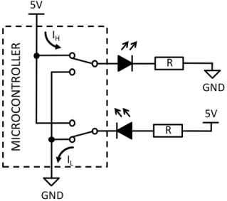
The Arduino board is a microcontroller whose pins are wired to connectors – so called pin headers – in order to ease access. Some supporting circuitry is used on the board so as to allow communication and to provide power. Many pins can be programmed as digital inputs or outputs, and in the latter case they can be used for driving external components including LEDs (see figure1) and other kinds of additional circuits.
Figure 1. The microcontroller’s outputs can be programmed to logic high or logic low states, when they can source IH or sink IL current, respectively. Accordingly, LEDs can be operated by using positive or negative logic.
Integrated circuits always have specifications including current drive capability and its limitations. If we look in the datasheet of the microcontroller of the Arduino Uno, we can find two sections of specifications: “Absolute Maximum Ratings” and “Common DC Characteristics” [1]. The meaning of
“Absolute Maximum Ratings” is always described briefly in the datasheets, since it is extremely important. Let’s see how can we interpret the three sentences of this explanation!
5V
GND
GND 5V IH
IL
R
R
MICROCONTROLLER
Accepted manuscript
Citation: Zoltan Gingl et al 2019 Phys. Educ. 54 025010
DOI: https://doi.org/10.1088/1361-6552/aafa41
Possible partial or full damage
“Stresses beyond those listed under “Absolute Maximum Ratings” may cause permanent damage to the device. “
This means that you should never exceed the absolute limits even under the worst conditions. What can happen otherwise? The device may not be damaged partially or completely, but the user can’t be sure any more if the device is still fully functional. You may think, that it is possible to determine if a part has been damaged, since you can check if it is working properly or not. However, even if it seems to work fine, you can’t be sure whether any partial degradation has occurred, and it is likely impossible to test all of the functionalities. If some degradation has already been started, it can lower the specified tolerance and can make the device more sensitive. Therefore, your system may fail unexpectedly, the reliability which is essential in any electronic equipment and system can be completely lost. To conclude, an engineer always throws away overstressed components even if they seem to work fine.
Normal operation is not guaranteed
“This is a stress rating only and functional operation of the device at these or other conditions beyond those indicated in the operational sections of this specification is not implied.”
This means that even if we are within these ratings, normal operation is not guaranteed if the recommended conditions are not met. We can’t be sure about the proper operation of our device in all aspects. It may behave unexpectedly and it can be more sensitive to the conditions.
Operation close to the limits is a bad practice
“Exposure to absolute maximum rating conditions for extended periods may affect device reliability.”
It speaks for itself, makes clear that the device is not designed to be operated at the limits. In such cases even a very small change can push it over the absolute maximums and continuous strong stress can increase the probability of faults.
Do people care these?
Most Arduino guides – even the official tutorial [2] – say that the device can drive 40 mA per pin even though it is specified as an absolute maximum. According to the abovementioned, it is certainly misleading and can encourage users to accept it as normal operation. It would be much better to say that pin drivers can survive the stress of sourcing or sinking 40 mA, and to tell you to always stay within the maximum value specified in the operational section, 20 mA (at VCC=5 V supply voltage) [1].
Fortunately, the official Arduino Uno board page is correct in this sense [3].
It is almost never mentioned that the currents entering/leaving the microcontroller at the supply pins (IVCC and IGND) are limited to an absolute maximum of 200 mA [1]. Figure 2 shows how the supply pin currents are related to the currents flowing between the board and external circuits.
Figure 2. Main currents flowing in the system. The sum of the sink and source currents of the external circuitry via the port pins are denoted with IH and IL. The board circuits’
and the microcontroller’s internal circuits contribute to the IVCC and IGND supply pin currents.
It is easy to see, that the 200 mA limitation contains the currents of the board and the
microcontroller as well. The sum of these typically fall below 20 mA, leaving an absolute maximum of about 180 mA for the external circuits.
There are further restrictions as well: the sum of the currents of specific groups of pins are also limited as shown in table 1.
Sum of all IH source currents of the following groups of pins is limited to 150 mA, VCC=5 V microcontroller pins boards pins estimated maximum
internal currents
remaining limit for external circuitry C0 - C5, D0 - D4
ADC7, RESET
A0 - A5, 0 - 4 RESET
5 mA 145 mA
B0 - B5, D5 - D7 ADC6, XTAL1, XTAL2
5 - 13 1 mA 149 mA
Sum of all IL sink currents of the following groups of pins is limited to 100 mA, VCC=5 V microcontroller pins boards pins estimated maximum
internal currents
remaining limit for external circuitry
C0 - C5, ADC7, ADC6 A0 - A5 1 mA 99 mA
B0 - B5, D5 - D7 XTAL1, XTAL2
5 - 13 1 mA 99 mA
D0 - D4, RESET 0 - 4, RESET 5 mA 95 mA
Table 1. Limitations for source/sink currents for groups of pins of the ATmega328P microcontroller [1] of the Arduino Uno board.
Internal circuitry
Port pins logic high
Port pins logic low
Other pins
Board
circuits EXTERNALCIRCUITS
5V
MICROCONTROLLER
GND IGND ILO IVCC
IHP
IHB
ILB
PIN HEADERS
ARDUINO BOARD
II
II
IHO
ILP
IH
IL
IVCC=IHP+IHO+II IHP=IH+IHB
IVCC=IH+IHB+IHO+II
IGND=ILP+ILO+II ILP=IL+ILB
IGND=IL+ILB+ILO+II
Examples – The Good, the Bad and the Ugly
In the “LED Bar Graph” example [4] 10 LEDs are connected to the pins via 220 Ohm resistors, so the current per pin is about 15 mA for red LEDs. When all LEDs are switched on, the total IVCC current contribution is close to 150 mA. It is acceptable, nevertheless a bit close to the limit, and it leaves only a small room for additions and modifications. The sums of currents flowing out via pins 2 - 4 (45 mA) and 5 – 11 (105 mA) are also within the specifications. However, when using negative logic (see figure 1), the 105 mA is too high as a sum of sink currents! It would be better to reduce the current to a more safe level.
The “Row-column Scanning to control an 8x8 LED Matrix” [5] shows no series resistors for limiting the currents of the LEDs. Consequently the 40 mA per pin absolute maximum is certainly violated, and if the user switches on more LEDs, other limits may also be exceeded.
Is it costly to damage a board?
Sometimes users say that Arduino is cheap, it is not a big trouble if it gets damaged. In addition, if only an output is damaged, the others can still be used. We think this is a very dangerous approach in teaching and learning. Education and practices are done within an isolated, protected environment, where one can make mistakes without serious consequences. However, the role of education is to prepare the students for the real life conditions, to be careful, well-informed and trustworthy. Just think about the many car recalls due to design mistakes, and that pilots must be serious about safety even during practicing with a flight simulator. Consistent feedback is very important in education as well. Violation of the rules must be painful in some sense, otherwise students won’t be stimulated to do things in the right way. High quality STEM and physics education is essential for the engineers, scientists, professionals and teachers of the future, so the real cost of damaging an Arduino or part of it can be high!
What is the physics in this?
Electronics is an important part of applied physics. One can say that as mathematics is the language of theoretical physics, electronics is the modern language of experimental physics and C++ of Arduino is a language of algorithms. Students learn about voltage, current, Ohm’s law, Kirchhoff’s laws, they solve and measure circuits in the physics classrom. They can play with electronic
components, various sensors and credit card sized computers [6,7]. Teachers and students can also access advanced integrated circuits which helped to detect gravitational waves! [8].
Absolute maximum ratings are not only important in electronics. Overheating a solid body can result in melting, overstressing can cause violation of Hooke’s law, and overpressure can explode a bottle.
In real life students see weight limits in an elevator, red range in the car tachometer. It is fun to find the universal physical principles behind these and many more.
The message
Teacher colleagues, students, developers! Be conscious, careful, respect the rules determined by leading experts, do not let a bad habit to be developed. Figure 3 warns you to always keep enough margin and not to drive blindfolded as Chaplin did in the roller skating scene of “Modern times” [9].
Read also an application engineer’s very clear notes on the subject [10] and some more about the physics background [11]. Do not forget, that absolute limits are important in other parts of our life as well – elevators, bridges, traffic, economy, social life, …
Figure 3. Always keep enough margin and do not drive blindfolded! [12]
Acknowledgments
This study was funded by the Content Pedagogy Research Program of the Hungarian Academy of Sciences. The authors would like to say thanks to Csaba Magyar for his imaginative illustration.
References
[1] ATmega328P, https://www.microchip.com/wwwproducts/en/ATmega328P [2] Digital pins, In: Arduino tutorials, https://www.arduino.cc/en/Tutorial/DigitalPins [3] Arduino Uno Rev3, In: Arduino products, https://store.arduino.cc/arduino-uno-rev3 [4] LED Bar Graph, In: Arduino tutorials/Built-In Examples,
https://www.arduino.cc/en/Tutorial/BarGraph
[5] Row-columm Scanning to control an 8x8 LED Matrix, In: Arduino tutorials/Built-In Examples, https://www.arduino.cc/en/Tutorial/RowColumnScanning
[6] Atkin J K 2017 Using the Arduino with Makerplot software for the display of electrical device characteristics Phys. Educ. 52 065007
[7] Kinchin J 2018 Using an Arduino in physics teaching for beginners Phys. Educ. 53 063007 [8] The Chirp Heard ’Round the Universe, Analog Devices, https://www.analog.com/en/landing- pages/001/ligo.html
[9] Chaplin: Modern times, roller skating scene, https://www.youtube.com/watch?v=kPcEFHA3X0c [10] John Ardizzoni, What’s the big deal about ABSOLUTE MAXIMUM RATINGS?, In: Analog Devices, Rarely asked questions, https://www.analog.com/en/analog-dialogue/raqs/raq-issue-50.html [11] James Bryant , Who Killed the Component?, In: Analog Devices, Rarely asked questions, https://www.analog.com/en/analog-dialogue/raqs/raq-issue-130.html
[12] Illustration by Csaba Magyar
![Table 1. Limitations for source/sink currents for groups of pins of the ATmega328P microcontroller [1] of the Arduino Uno board](https://thumb-eu.123doks.com/thumbv2/9dokorg/1285965.102818/3.892.105.786.716.1017/table-limitations-source-currents-groups-atmega-microcontroller-arduino.webp)
![Figure 3. Always keep enough margin and do not drive blindfolded! [12]](https://thumb-eu.123doks.com/thumbv2/9dokorg/1285965.102818/5.892.112.780.286.744/figure-margin-drive-blindfolded.webp)
