Voltmeter in series?
Zoltan Gingl and Robert Mingesz
Department of Technical Informatics, University of Szeged, Árpád tér 2, 6720 Szeged, Hungary E-mail: gingl@inf.u-szeged.hu
Abstract
A recent physics challenge shows a circuit, where a voltmeter is connected in series. Indeed, real voltmeters have finite input resistance, therefore, one may think that they can be used as resistors.
In addition, voltmeters measure the voltage difference between their terminals, so it seems to be possible to calculate the current flowing through them. Is it okay? Are there any hidden secrets? The underlying methodology is related to high-quality physics and STEM education, which are
increasingly important in the modern world. On one hand, it can be considered as an approval of an improper use that one can never see in any textbook and application, and it may also occur that suggesting and teaching such uncommon solutions can generate an undesired attitude. On the other hand, one can also say that if the students are taught to always follow the application rules, then the development of their creativity can be hindered. We do think it deserves some discussion.
The voltmeter-in-series circuit
Figure 1 shows the circuit of the challenge “Why so series?” [1, 2].
Figure 1. Circuit of the challenge [1, 2]. The meters show 6 mA, 0.5 V and 3.0 V.
Looking at the voltmeter in series can be confusing, since it is used as a conducting element.
Although real voltmeters have finite input resistance and some current can flow through them, it is taught, that voltmeters should always be connected in parallel to the component on which the voltage drop is measured regardless of the value of their input resistance.
Seeing such an anomalous use of the voltmeter shown above, one may think that it is not necessary to follow the application rules, the situation can be easily handled, and there are no reasons to worry. In this spirit, despite it is taught that ammeters must always be inserted in series, it could be considered as normal to connect a non-ideal ammeter in parallel. Therefore, it can be used as a
A V
V
R 3R
R 3R
6 mA 3 V
0.5 V
Accepted manuscriptCitation: Zoltan Gingl and Robert Mingesz 2019 Phys. Educ. 54 045017 DOI: https://doi.org/10.1088/1361-6552/ab22ff
resistor such as the voltmeter in the challenge. In addition, one could also come up with a circuit, where two different voltage sources with non-zero internal resistances are connected in parallel, assuming that no short circuits have been created, see figure 2. Looking at these circuits likely makes most of us feel uncomfortable, since we know that connecting voltage generators and ammeters in parallel can even cause damage.
Figure 2. Theoretically it seems to be allowed to connect non-ideal ammeters and voltage sources with certain non-zero internal resistances in parallel.
Other examples can also be mentioned. Real capacitors can have some DC conductance (typically modelled by a resistor in parallel) and inductors can have considerable series resistance [3]. Thus, in theory, they could be used as resistors in DC circuits just like the voltmeter in figure 1. However, it is never done in practice.
We believe, it is worth to discuss the methodology behind the voltmeter-in-series example and especially its relation to education.
Ideal and real voltmeters and ammeters
It is well known that a perfect instrument must not affect the operation of the observed system.
Therefore, an ideal voltmeter behaves like an open circuit, while an ideal ammeter acts as a short circuit. In electronics, real components are modelled by combinations of ideal components. A real voltmeter is represented by an ideal voltmeter and a resistor, or more generally, an impedance, connected in parallel (see figure 3). It acts like an impedance, it can conduct current. Similar is true for real ammeters, they can also function as impedances. From this point of view, only their very different practical impedance values separate them.
Figure 3. A real voltmeter or ammeter can be modelled as a parallel or serial combination of an ideal meter and an impedance, respectively. Both function as impedances in the circuit, but their real values are very different.
Using voltmeters
In practice the impact of the input impedance of voltmeters on the system operation must be negligible. Therefore, there is always a certain limit of application, since the required accuracy must not be compromised by the presence of the input impedance. For most digital multimeters (DMM) the value is 10 MΩ, while oscilloscope inputs typically load the signal source with 1 MΩ. Note, that in
V
1V
2?
A R V
?
R
V
Z
IN,VZ
IN,VA
Z
IN,AZ
IN,Athe challenge the input impedance of the voltmeters equals 500 Ω, which is 20000 times less than the typical input impedance of today’s voltmeters.
In some exceptional cases low input impedance can be desirable. High speed signals may need proper termination to avoid reflections [4], therefore, oscilloscope inputs can have a very low input impedance of 50 Ω. Low impedance (Lo Z) mode of voltmeters also exist in order to cancel the so- called ghost voltages that are typically present as parasitic voltages in non-energized mains circuits [5]. Although the input impedance can be low, the voltmeters are always connected in parallel.
Can we take the input impedance of a voltmeter into account?
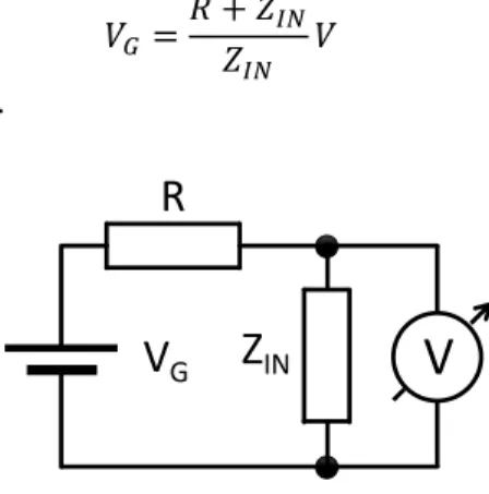
One may think that the value of the input impedance ZIN of the voltmeter can be taken into account and the voltmeter can even be used to determine the current flowing through it as it was done in the challenge. For instance, the VG voltage of a generator connected to the voltmeter via a series resistor R in figure 4 can be calculated as
𝑉𝐺 =𝑅 + 𝑍𝐼𝑁
𝑍𝐼𝑁 𝑉 (1)
where V is the measured voltage.
Figure 4. If the series resistor R and the input impedance ZIN is known, VG can be determined using the value measured by the voltmeter.
Similarly, if a current I flows through the input impedance of the voltmeter (figure 5), its value can be expressed as
𝐼 = 𝑉
𝑍𝐼𝑁 (2)
Figure 5. The voltmeter shows the voltage equal to the current multiplied by the input impedance.
For example, consider a 4.5 digit DMM having 10 MΩ input impedance according to the datasheet. If it displays a value of 1.0000 V and R is 10 MΩ, then VG is calculated as 2.0000 V. In the same case, the current that flows through ZIN equals 0.1000 μA.
It seems to be very straightforward. However, doing so is not a good practice at all! Let us see why.
Z
INV
R
V
GZ
INV
I
Input impedance variants and specifications
All instruments have accuracy specifications and defined normal operating conditions, otherwise the measured value would be unreliable and useless. Although the voltage measurement accuracy of a voltmeter is always given, in contrast, the tolerance of the input impedance is rarely specified.
Therefore, using the nominal value in calculations introduces unknown errors and can even cause the loss of reliability.
Let us see some examples. A leading manufacturer specifies the input impedance of their DMM only as >10 MΩ in DC voltage measurement mode (see the “Fluke 114, 115, 116 and 117 Digital
Multimeters Extended specifications”, https://dam-assets.fluke.com/s3fs-
public/2793260_6116_ENG_A_W.PDF ). We think the message is clear: do not assume anything about its actual accuracy, use it only, when its effect is negligible. In other words, don’t try to use the nominal value of the input impedance to compensate its effect or to calculate the current flowing through it. Note, that during AC voltage measurements the input impedance of the same instrument is given as >5 MΩ.
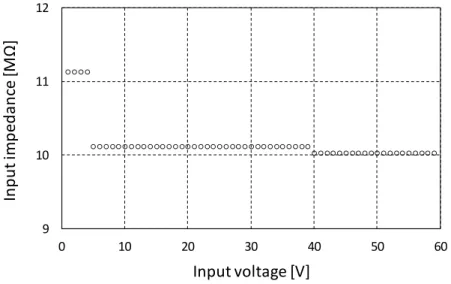
The manual of our UT60H 4.5 digit DMM used in education says that the voltage measurement accuracy is 0.1%+5 counts (this means 0.15% overall error for 1.0000 V), while the input impedance is specified as “Approx. 10 MΩ”. Some other DMMs’ datasheet may say “about 10 MΩ”, or “10 MΩ nominal” or just “10 MΩ”. We have measured the input impedance of this DMM as a function of the input voltage, see figure 6.
Figure 6. Input resistance as a function of the input voltage for a 4.5 digit multimeter under test (UT60H). The value is different in the measurement ranges of 4 V, 40 V and 400 V.
One can see that the value can be more than 10 % apart from the nominal value and it depends on the selected measurement range too. Thus, using the measured 11.12 MΩ value in equation (1) and (2) gives 1.8993 V and 0.0899 μA in the abovementioned example instead of 2.0000 V and 0.1000 μA.
Therefore, using the nominal value introduces an error which is about 33 and 67 times higher than the error caused by the DMM itself!
What is the reason for such surprising and significant variations in the input impedance that can make even electronics enthusiasts and professionals sometimes confused?
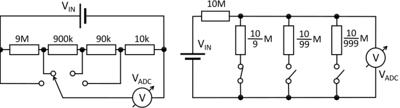
There are typically two solutions in DMMs to set the input voltage range. Manual range selection is done by using a rotary switch that changes the voltage division ratio, see the left hand side circuit of
9 10 11 12
0 10 20 30 40 50 60
Input impedance [MΩ]
Input voltage [V]
figure 7. In this case the input voltage source always sees a constant load close to 10 MΩ regardless of the range. Auto-ranging DMMs change the division ratio using integrated circuit switches.
Accordingly they typically employ a more suitable solution that can be seen on the right hand side of figure 7. The input impedance depends on the selected range in this case as we have observed. There are even such auto-ranging DMMs, where the input impedance at the lowest ranges can be well above 1000 MΩ (all switches are off), while in other ranges their nominal impedance is still close to 10 MΩ.
Figure 7. Principles of voltage divider circuits used in manual (left hand side) and auto- ranging voltmeters (right hand side) to select the division ratio of the input voltage VIN in order to provide a voltage VADC for analogue-to-digital conversion.
In conclusion, there are several implementations of DMMs with various input impedance values that may depend significantly on an automatically selected range. In general, the actual value and its accuracy can’t be considered as known, in several cases only a minimum or approximate value is specified. Therefore, it is a bad practice to use the voltmeters in such conditions when their input impedance matters. There are only a few exceptions in some special cases. When using high-voltage DMM probes or attenuating oscilloscope probes, the input impedance can be a part of a voltage divider as shown in figure 4. However, in this case the user (typically an expert) must have an in- depth knowledge about the input impedance of the used instrument.
Principles in STEM education
In technology, engineering and related sciences (but also in other fields including communication, economy, traffic, etc.) well-established standards and rules are used to guarantee proper operation and reliability which are essential for all electronic systems. Therefore, instruments and electronic components must always be used according to the specifications. In addition, there are no reasons to do the opposite. Violation of the rules and standards, ignoring implicit or explicit warnings can be dangerous. These can lead to unexpected operation and getting used to these can result an undesirable attitude [6,7]. High-quality STEM and related physics education play a very important role in developing carefulness, reliability and right attitude of professionals, engineers, scientists and teachers of the future. Education should prepare the students for real life jobs, therefore, it should take the well-established rules of technology and engineering seriously. Thus, we believe that teachers should never suggest that it is not necessary to follow the rules of correct application. If the students do leave the right way, they should be asked why they think that their solution is good and if they really considered all of the consequences. Furthermore, the teacher can help to analyse the potential problems of their solution and can draw the attention to possible unfounded assumptions.
The final message should be that the rules of correct application should always be followed.
Let’s go back to the circuit shown in figure 1 for a while. The intention was probably to recognize a really important feature of voltmeters. The problem is only with the message that connecting a
9M 900k 90k 10k
V
INV
ADC10M
V
INV
ADC10 999M 10
99M 10
9 M
V
V
voltmeter in series and applying it as a resistor is normal, there are no reasons to worry, while teachers and students can never find this in any textbook or application. It certainly violates the rules of correct application and we have shown, that it is a bad practice to relate the voltage and current of a voltmeter as it was done in the challenge. Teaching creative thinking about the input impedance can be done without such an odd suggestion, see a recent paper in Physics Education [8]. The aim can be to observe the effect and to understand the limitations, but not to suggest irregular applications.
One may say, that forcing to follow the rules limits the possibilities available to the students, however, it does not limit the development of creativity. It is a typical real-life challenge to find a smart solution when the conditions are given and engineers and scientists should be good at this.
Most of the teachers probably experience that students often gain knowledge by memorizing figures and arrangements, they accept as recommended what they see during the lectures. Irregular use of a component without any warning can mislead students, but can be confusing even if the teacher says that it may not work properly in practice. Understanding the operation out of normal conditions needs high level of expertise typically only experienced professionals, engineers and scientists have.
This certainly exceed what can be expected from teachers and students.
Conclusion
More and more modern tools and solutions are available to the students and teachers formerly used only by experts. Examples include DMMs and other accurate electronic instruments, electronic components, sensors, microcontrollers (e.g. Arduino boards often used by students and physics teachers [9-11]) and software development tools. These are very useful in high-quality STEM and physics education, but sometimes important rules of correct application are violated. For example, it is rather common within the Arduino community that a built system does not work reliably, some components may even get damaged [6]. In several cases the users do not know the reasons and they may not aim to design the system carefully by following the essential rules of technology. Instead, they often rely on some kind of “black magic” and they hope to find the right operating conditions by thoughtless random attempts. This attitude is far from being acceptable in any kind of education.
Related examples and analysis can be found in some recent papers [6,7,12-14].
We believe that tools, devices and components should never be used out of their normal operation modes and differently from what they were designed for. It is not needed to help in understanding, furthermore it can be misleading and it can generate unexpected and overlooked errors and can confirm questionable applications more generally. Just like during teaching the traffic rules: never suggest to drive in the wrong direction in a one-way street or to go when the red light is on, even if it seems to be possible and safe. These are valid options only for authorized persons, like drivers of ambulance cars, and only in case of emergency. They must have a special training to learn what to do in such exceptional situations.
Finally, see figure 8 that draws the attention to the importance of teaching about the most important rules that help students do the things right and safe.
Figure 8. Teaching students to understand and follow the well-established rules helps to avoid unexpected risks and to make them thoughtful. Reproduced with permission from Csaba Magyar.
Acknowledgments
This study was funded by the Content Pedagogy Research Program of the Hungarian Academy of Sciences. The authors thank Csaba Magyar for his imaginative illustration.
References
1. Boris Korsunsky 2018 Why so series? Phys. Teach. 56, 269 (https://doi.org/10.1119/1.5028252)
2. Solution to the April, 2018 Challenge, Why so series? Phys. Teach. 56, C489 (https://doi.org/10.1119/1.5055312)
3. James Bryant, Walt Jung, Walt Kester, SECTION 7-1 - Passive Components, Editor(s): Walt Jung, Op Amp Applications Handbook, Newnes, 2005, Pages 609-628, ISBN 9780750678445, (https://doi.org/10.1016/B978-075067844-5/50149-1) Open access version
(https://www.analog.com/media/en/training-seminars/design-handbooks/Op-Amp- Applications/Section7.pdf )
4. Electrical termination. Wikipedia (https://en.wikipedia.org/wiki/Electrical_termination) 5. Dual Impedance Digital Multimeters, Fluke (https://www.fluke.com/en-us/learn/blog/digital-
multimeters/dual-impedance-digital-multimeters)
6. Gingl Z, Mingesz R, Makan G and Mellar J 2019 Driving with Arduino? Keep the lane! Phys.
Educ. 54 025010
7. Gingl Z, Makan G, Mellár J, Vadai G and Mingesz R 2018 Phonocardiography,
photoplethysmography with simple Arduino setups to support interdisciplinary STEM education, figshare (https://doi.org/10.6084/m9.figshare.7308356.v1)
8. Stojilovic N and Isaacs D E 2018 Resistance of a digital voltmeter: teaching creative thinking through an inquiry-based lab Phys. Educ. 53 053005
9. Kinchin J 2018 Using an Arduino in physics teaching for beginners Phys. Educ. 53 063007 10. Atkin J K 2018 An Arduino-based experiment designed to clarify the transition to total
internal reflection Phys. Educ. 53 025003
11. Atkin J K 2018 Investigating the Torricelli law using a pressure sensor with the Arduino and MakerPlot Phys. Educ. 53 065001
12. Makan G, Mingesz R and Gingl Z 2019 How accurate is an Arduino Ohmmeter? Phys. Educ. 54 033001
13. Gingl Z, Makan G, Mellár JZ 2018 Arduino data conversion – 1023 or 1024? figshare (https://doi.org/10.6084/m9.figshare.7434074)
14. Gingl Z, Makan G, Mellár JZ 2018 Buttons connected to Arduino – can they be dangerous?
figshare (https://doi.org/10.6084/m9.figshare.7434023 )
![Figure 1 shows the circuit of the challenge “Why so series?” [1, 2].](https://thumb-eu.123doks.com/thumbv2/9dokorg/1315933.105936/1.892.343.545.638.894/figure-shows-circuit-challenge-series.webp)