Journal of Petroleum Science and Engineering 208 (2022) 109424
Available online 24 August 2021
0920-4105/© 2021 The Authors. Published by Elsevier B.V. This is an open access article under the CC BY license (http://creativecommons.org/licenses/by/4.0/).
Effects of vertical anisotropy on optimization of multilateral well geometry
Marcell Lux
a,b,*, J anos Szanyi ´
aaUniversity of Szeged, H-6722, Szeged, Egyetem u. 2-6, Hungary
bMOL Plc., H-5000, Szolnok, Ady E. u. 26, Hungary
A R T I C L E I N F O Keywords:
Multilateral wells Permeability anisotropy Unstructured grids Geothermal energy Oil- and gas production
A B S T R A C T
Multilateral wells have been increasingly used in recent years by different industries such as the oil- and gas industry (incl. coal-bed methane (CBM)) and geothermal energy production. The common purpose of these wells in the oil industry and partially in the geothermal industry is to achieve a higher production rate per well without increasing the hydraulic gradient significantly. In geothermal systems the ultimate objective is to improve heat extraction performance by enhancing productivity but also by increasing the heat transfer area.
Optimal design of multilateral wells has been the focus of numerous publications in CBM and unconventional oil- and gas production, but as a result of cross-fertilization and technology-transfer among different sectors in the energy industry in the last few years, the focus of research on multilateral wells has turned to enhanced geothermal systems (EGS).
Recently, several papers have been published on the use of multilateral wells in deep geothermal reservoirs.
Coaxial closed-loop geothermal systems with multilateral wells utilize only the increased heat transfer area due to the laterals while EGS’s with multilateral injection and production wells also benefit from the hydrodynamic advantages of such well configurations. However, substantial emphasis is – understandably – placed on the effect of artificial and natural fracture networks of EGS reservoirs and less focus is devoted to the impact of vertical permeability anisotropy which can seriously influence the flow pattern of a given configuration. Similarly, in CBM-related studies, the effect of horizontal permeability anisotropy along the face cleats to the butt cleats on multilateral well-design was investigated and vertical permeability anisotropy was not considered.
In the current work we present a generalized approach for evaluating the effects of vertical permeability anisotropy on multilateral well geometry by numerical hydrodynamic modelling in an idealized, homogeneous hydrogeological setting.
Current paper proposes an alternative modelling approach for representing the non-horizontal branches of multilateral wells by introducing a thin layer for the laterals with the same inclination as the well branches. This approach is then is used to investigate the effect of anisotropy on the flow pattern and near-wellbore drawdown and hydraulic gradient in the case of different branch deviations. Results suggest that the benefits of highly deviated or horizontal laterals emerge when vertical anisotropy is high. Evaluation of branch deviation vs.
anisotropy indicates that above approx. 60◦there is no significant benefit in increasing deviation which implies that very highly deviated or horizontal laterals might not necessarily pay off the associated technical challenges and extra costs.
1. Introduction
Multilateral wells are defined as wells with a common trunk from where two or more laterals are drilled. Laterals may be vertical, hori- zontal or deviated and are not necessarily in the same plane (Garrouch et al., 2004). This suggests that the variations of multilateral well pat- terns are only limited by technology and imagination. In practice, the applied well geometry depends on drilling technology, geological
environment and reservoir conditions.
Multi-branched wells have been increasingly used in recent years by different industries such as the oil and gas industry (incl. coal-bed methane (CBM)) and geothermal energy production. The common purpose of these wells in the oil industry - and partially in the geothermal industry - is to achieve a higher production rate per well without increasing the hydraulic gradient significantly. In geothermal systems the ultimate objective is to improve heat extraction perfor- mance by enhancing well productivity but also by increasing heat
* Corresponding author. University of Szeged, H-6722, Szeged, Egyetem u. 2-6, Hungary.
E-mail address: lux.marcell@gmail.com (M. Lux).
Contents lists available at ScienceDirect
Journal of Petroleum Science and Engineering
journal homepage: www.elsevier.com/locate/petrol
https://doi.org/10.1016/j.petrol.2021.109424
Received 24 November 2020; Received in revised form 28 July 2021; Accepted 21 August 2021
Journal of Petroleum Science and Engineering 208 (2022) 109424 transfer area.
With the expected continuing advancement in technology, more sophisticated well patterns and geometries are possible to implement in practice (Zhou et al., 2008; Yang et al., 2014; Kov´acs et al., 2014; Bajcsi et al., 2015; Li et al., 2019; Song et al., 2019 and Zhe and Zhongwei, 2019). Multilateral wells can also offer an alternative to hydraulic fracturing in certain areas of unconventional hydrocarbon production, such as gas production from coal-beds and ductile shale layers, where, due to the ductile behaviour of rocks, artificial fractures will close around the proppant and well productivity will be reduced (Slatt, 2011;
Ren et al., 2014 and Torghabeh et al., 2014). Liu et al. (2018) investi- gated CBM recovery from multi-lateral wells in Southern Qinshui Basin, Nomenclature
Kh horizontal hydraulic conductivity, m⋅s−1 Kh vertical hydraulic conductivity, m⋅s−1
Kx, Ky, Kz hydraulic conductivity in x, y and z directions, m⋅s−1 Kh/Kv vertical anisotropy factor, dimensionless
Qlateral flow rate per lateral, m3/d α deviation of lateral from vertical, ◦ dh/dl hydraulic gradient, dimensionless
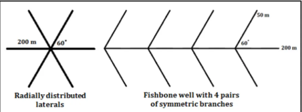
Fig. 1. Types of multilateral well.
Fig. 2. Representation of lateral well branches in a horizontal layer.
Fig. 3.Representing lateral well branches by a thin deviated layer (grey layers are aquitards, brown are transitional and blue are aquifers.
M. Lux and J. Szanyi
where numerical simulations proved that several fishbone-type multi-- lateral wells can achieve a close to complete field drainage with 90% gas recovery over a high percentage of the drainage area.
Optimal design of multilateral wells has been the focus of numerous publications in CBM and unconventional oil- and gas production (Yeten et al., 2003; Maricic et al., 2008; Chen et al., 2012; Lyu et al., 2018), however as a result of cross-fertilization and technology-transfer among different sectors in the energy industry in the last few years the focus of research on multilateral wells has also turned to enhanced geothermal systems (EGS) (Shi et al., 2019d; Erol et al., 2021).
Recently several papers have been published on the use of multi- lateral wells in deep geothermal reservoirs. Coaxial closed-loop geothermal systems with multilateral wells only utilized the increased heat transfer area (Wang et al., 2021a) due to the laterals while EGS’s with multilateral injection and production wells also benefit from the hydrodynamic advantages of such well configurations (Song et al., 2018;
Shi et al., 2018, 2019d, 2021; Erol et al., 2021). However, substantial emphasis is - understandably – placed on the effect of artificial and natural fracture networks of EGS reservoirs (Shi et al. 2019a, 2019b, 2019c, 2019b; Ren et al., 2020) and only limited focus has been devoted to the impact of vertical permeability anisotropy which can seriously influence the flow pattern of a given configuration (Erol et al., 2021).
Fig. 4.Representing lateral well branches by a thin deviated layer (grey layers are aquitards, brown are transitional and blue are aquifers).
Fig. 5. Multilateral well in the unstructured model domain in perspective view.
Fig. 6. Vertical hydraulic sections comparing the hydraulic head patterns around laterals in case of the two modelling approaches (A: vertical refining, B: thin inclined layer for the laterals, red colour represents the laterals).
Journal of Petroleum Science and Engineering 208 (2022) 109424
Similarly, in CBM-related studies, the effect of horizontal permeability anisotropy along the face cleats to the butt cleats on multilateral well-design was investigated and vertical permeability anisotropy was not considered (Chen et al., 2012).
In current work we present a generalized approach by evaluating the effect of vertical permeability anisotropy on multilateral well geometry by numerical hydrodynamic modelling in an idealized, homogeneous hydrogeological setting.
In a previous paper (Lux et al., 2016) it has been demonstrated that unstructured grids are more efficient in modelling multilateral wells than structured grids from a computational point of view while also providing better resolution. That paper also investigated optimal ge- ometries for radially distributed and fishbone type multilateral wells in a homogenous, isotropic environment. The current paper investigates the
effect of vertical anisotropy on the optimal multilateral well geometry.
The first part of the paper proposes an alternative modelling approach for representing the non-horizontal branches of the multilat- eral wells by introducing a thin layer for the laterals which has the same inclination as the well branches. This modelling method is then compared to a more conventional modelling approach and its advan- tages are highlighted. In the second part the results of numerous modelling scenarios are summarized, focusing on the effect of anisot- ropy on the flow pattern and near-wellbore drawdown in case of different branch deviations and flow rates.
2. Methodology – modelling approach 2.1. Unstructured grid
In present work – building on the advantages demonstrated previ- ously (Lux et al., 2016) – we applied unstructured grids (USG) to model multilateral wells using the MODFLOW-USG code that simulates groundwater flow using a generalized control volume finite-difference approach, which allows grids other than orthogonal structured grids (SG) (Panday et al., 2013).
For modelling, we used Groundwater Modelling Software (GMS) which has the MODFLOW-USG code built-in for different types of un- structured grids. Based on previous experiences the Voronoi (or Perpendicular Bisector, PEBI) grid type was selected as it is best fit to describe multilateral well geometry with the required resolution and computational efficiency. An et al. (2012) used PEBI grids to model fractured horizontal wells and argue that both the main wellbores and the fractures can be better represented by PEBI grids compared to Car- tesian grids, as PEBI grids can be constructed to follow the orientation of the wellbores and fractures. Syihab et al. (2014) developed a gridding algorithm that enable Voronoi grids to conform fracture networks with intersecting faults. Multilateral wells can also be considered as linear, intersecting features, similarly to faults and fracture networks, therefore Voronoi grids present a suitable grid-type for modelling multi-branched wells.
2.2. Model geometry, parameters and boundary conditions
There are two main types of multilateral well patterns: (i) radially distributed laterals originating from one vertical trunk and (ii) the so- called fishbone (or herringbone) wells, where laterals are drilled from a horizontal trunk (Fig. 1) (Cai et al., 2013).
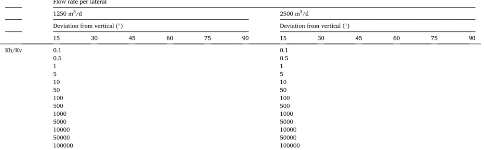
Our previous work (Lux et al., 2016) investigated the optimal ge- ometries for radially distributed and fishbone type multilateral wells in a homogenous, isotropic environment. Not only the impacts of the Table 1
Modelling scenarios.
Flow rate per lateral
1250 m3/d 2500 m3/d
Deviation from vertical (◦) Deviation from vertical (◦)
15 30 45 60 75 90 15 30 45 60 75 90
Kh/Kv 0.1 0.1
0.5 0.5
1 1
5 5
10 10
50 50
100 100
500 500
1000 1000
5000 5000
10000 10000
50000 50000
100000 100000
Fig. 7.Definition of branch angles, red colour showing the cases described in detail.
M. Lux and J. Szanyi
number of laterals, but also the length of laterals, and – in case of fish- bone type wells – the angle of branches with respect to the main trunk were investigated. Results were in agreement with the findings of other authors. In the current paper we are only discussing well patterns with radially distributed laterals.
Zhang et al. (2018), Kou and Wang (2020) and Wang et al. (2021b) modelled Multiple Fractured Vertical Wells (MFVW) with a similar geometric pattern to the one presented on the left side of Fig. 1. How- ever, one of the main differences is that they modelled Multiple Radial Hydraulic Fractures (MRHF) with radially distributed vertical planes Fig. 8. Hydraulic head distribution around multilaterals at different angles and anisotropy factors, left side shows 30◦, right side shows 60◦, for three different anisotropy factors (scales are the same for all six figures).
Journal of Petroleum Science and Engineering 208 (2022) 109424
while we are using inclined linear elements to model the well branches.
The direction of the multilateral branches is technically much-better controlled than that of the fractures, therefore the above-described geometric pattern can be an almost exact representation of the laterals while it is an approximation for the MRHF.
MRHF induce micro-fracture networks around the wellbore and the main radial fractures which create a so-called Stimulated Reservoir Volume (SRV) with increased permeability. Such stimulated region does not occur around the lateral well branches, the original permeability of the rock is mainly preserved. Consequently, the transient effects that occur for MFVW due to different permeabilities of the stimulated and un-stimulated regions around the MFVW, will not manifest for multi- lateral wells.
MRHF are considered to have infinite conductivity and since they are modelled as vertical planes, the vertical permeability anisotropy of the rock has negligible impact on the performance of multi-wing hydrauli- cally fractured vertical wells. On the contrary, deviated multi-lateral wells are seriously affected by vertical permeability anisotropy as it will be demonstrated later.
Our previous work established that the optimum configuration (with regards to minimizing drawdown near the wellbore) for radially distributed multilateral wells is 8 lateral branches, because above this number, laterals impact each other that results in an undesirable in- crease of drawdown near the wellbore. Consequently, we used 8-branch multilateral configurations to evaluate the effect of vertical anisotropy.
The main question investigated how the hydraulic head distribution is affected around the wellbore and the laterals by different vertical anisotropy factors if the laterals are not horizontal but deviated from vertical.
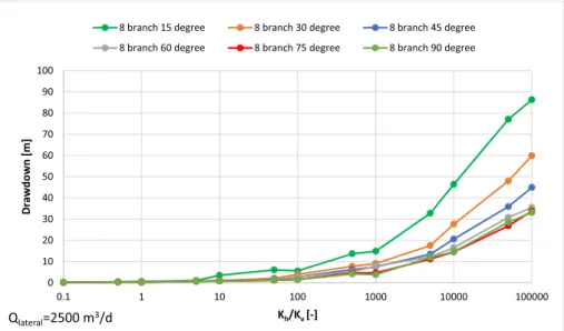
Once laterals are not horizontal, an issue with model geometry ari- ses: the grid is only unstructured laterally but vertically it is structured which means the cells are prisms with bases of Voronoi polygons. Since laterals are modelled as cells with very high permeability, refining is not only necessary laterally but also vertically to follow the deviation of the lateral and achieve the same resolution vertically as horizontally (0.5–1 m cell size). The longer the lateral the more layers need to be split up into ~1 m thick layers to reach the necessary refinement. This signifi- cantly increases the number of cells in the model domain, including Fig. 9. Drawdown vs. anisotropy at different branch angles (represented by different colours) with 2500 m3/d flow rate per lateral.
Fig. 10.Drawdown vs. anisotropy at different branch angles (represented by different colours) with 1250 m3/d flow rate per lateral.
M. Lux and J. Szanyi
areas where it is unnecessary and demands more CPU power when running the model.
On Fig. 2 it is observable that there is also an issue with some of the cells representing the branches: they only connect with their edges, not their sides which “brakes” flow within the lateral branch. To resolve this, extra cells (green cells) need to be introduced so that all neighbouring cells are side-facing each other.
Even with the above-mentioned refinements and adjustments the model will still not follow exactly the direction of the laterals as it will be a “stair-like” pattern. These problems do not appear if the well branches are located in a layer which has exactly the same inclination as the laterals. In this case it is sufficient to have only one thin layer that in- cludes the multilateral well branches. Layers above and below can have gradually increasing thickness to avoid numerical problems arising from neighbouring layers with very different thicknesses. Of course, there will
Fig. 11.Drawdown vs. branch angle at different anisotropy factors (represented by different colours).
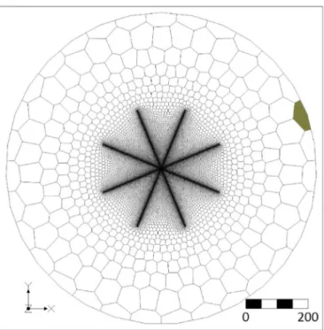
Fig. 12.Location of the cell selected for analysing vertical flow distribution (highlighted with olive-green colour).
Fig. 13.Percentage of total flow entering the aquifer at different anisot- ropy factors.
Fig. 14.Percentage of total flow entering the laterals’ layer at different anisotropy factors.
Journal of Petroleum Science and Engineering 208 (2022) 109424 still be some “artificial” spatial refinement for the purpose of fitting in
the laterals, but as our example below will demonstrate, significantly less than by splitting-up a great part of the model domain into thin layers.
As mentioned above, the 8-branch multilateral configuration was selected for evaluation. The model domain is a 1000 m diameter, 700 m high cylinder. The top of the cylinder is 500 m the base is − 200 m. There is a 34.5 m thick aquifer (base case: Kh/Kv =1: Kx =Ky =Kz =10−4 m s−1), between the two aquitards (base case: Kh/Kv =1: Kx =Ky =Kz = 10−6 m s−1). Between the aquifer and the aquitards transitional layers (Kx =Ky =Kz =10−5 m⋅s−1) are inserted, as in real field conditions there is often a gradual transition from reservoir rock to seal with decreasing grain size, porosity and permeability; a typical example is the upward- fining Bouma-sequences of deep-water turbidites (Shanmugam, 2006).
The transitional layer also decreases the risk of any numerical errors arising from huge differences in the permeability of neighbouring layers.
The multilateral branches are modelled as cells with very high hy- draulic conductivity (10 m□s−1). In the middle of the aquifer, at the point where the branches intersect, pumping wells are introduced to the eight endpoints of the branches with the total flow rate equally distributed. Boundary conditions are constant head cells in all layers on the edge of the model domain. Simulations were run in steady-state conditions, therefore transient effects in the early production periods are not investigated.
These three zones of hydraulic conductivity are divided into further layers to provide the required resolution. The USG is refined around the 8-branch multilaterals so that the branches are built up by Voronoi cells of about 75 cm “diameter”. Resolution is gradually decreasing as we move away from the laterals. This means that there are 27,343 cells/
layer in the entire model domain. Let us keep all layers horizontal for simplicity. If multilateral branches are not horizontal but deviated, the layer within which the well branches are located needs to be divided into at least 1 m thick sub-layers in order to reach the same resolution vertically as horizontally. In our example we considered a multilateral configuration with eight, ~42 m long branches that are deviated ~67◦ from vertical (inclination ~ 23◦) (Fig. 3). This will result in 17 extra layers of 1 m thickness, 34 layers all together on the model domain.
An alternative solution – as already discussed above – is to have a separate layer that exactly follows the inclination of the lateral well branches. Theoretically it could be very thin, even a few centimetres – similar to the real diameter of the laterals – however for numerical stability it is better to maintain approximately isometric cells, so in our case, as the horizontal resolution in the laterals is 75 cm we used a 50 cm thick layer in which to place the well branches. On Fig. 4 it can be seen, that the aquifer layer with the laterals is divided into several layers that have gradually increasing thickness as we move away from the lateral.
This is to prevent numerical instability from neighbouring layers with hugely different thickness. In this case it will result in 17 layers for the model: exactly half of what is needed for the previous approach.
Fig. 5 shows the layer including the laterals in perspective view. Cells are coloured based on Kh value, blue cells represent the laterals with Kh
= 10 m□s−1. Yellow spots indicate the pumping wells mentioned earlier.
With this approach the inclination of the laterals can be followed exactly with all the cells side-facing each other and a more realistic
“pipe-like” representation of the lateral branches is provided.
The question inevitably rises: how will the hydraulic head distribu- tion around the laterals compare between the two described approaches.
We have run the simulation for both cases and extracted the hy- draulic heads for all layers from the model and prepared a vertical hy- draulic cross section through the SSW-NNE lateral pair for both model variants (Fig. 6). Since the laterals and model parameters are symmet- rical the hydraulic head pattern around any of the other coplanar lateral pairs will be identical.
Comparing the two pictures it is clear – as already mentioned – that the model with the thin inclined layer provides a much more realistic
representation of the lateral well branches. The hydraulic head distri- bution is – however – very similar. The contour interval and colour scale are the same on the two pictures so slightly higher drawdown is observable on the left, where the laterals are introduced to the model by vertically refining the layers. This might be explained by the imperfect geometrical model of the laterals reducing their overall conductance that results in increased drawdown - as opposed to the inclined cells where flow is “undisturbed”. This is also considered an important advantage for the “inclined layer” approach besides the significantly reduced amount of necessary refinement in the model domain. There- fore, in the following investigations this approach will be used.
If the actual inclination of a layer in a real-life model is different from that of the lateral, than a layer for the lateral can still be introduced but need to pinch-out at the end of the lateral. This will be more complicated to achieve technically but it will still avoid the introduction of many extra sub-layers to reach the required resolution.
3. Results and discussion
The original question was how the hydraulic head distribution is affected around the wellbore and the laterals by different vertical anisotropy factors if the laterals are not horizontal but deviated from vertical. In order to find the answer, we have run and compared numerous model scenarios with several different anisotropy factors, well flow rates, and lateral deviations. Table 1 summarizes these scenarios.
As for the model, the only difference to the above described model is that the length of the laterals is 200 m in each scenario. Although our model is idealized, it can help testing the viability of a new technology (Kov´acs et al., 2014; Bajcsi et al., 2015) by providing a good basis for comparison with real field examples. Very high anisotropy factors (50000, 100000) may be unrealistic, but can be considered as extreme maximum values and help to confirm trends with increasing anisotropy.
It is obvious that we cannot present the result graphically for all scenarios in this paper but in order to visualize some of the main ob- servations, Fig. 8 below shows the hydraulic head pattern for 3 different anisotropy factors in case of 30◦and 60◦deviation of the laterals from vertical (shown in red on Fig. 7).
What we can observe is that by increasing the anisotropy factor (i.e.
decreasing vertical hydraulic conductivity) drawdown will increase in general and also the depressed area around the centre – where the lat- erals connect – will extend at both angles. At the same anisotropy factor, higher angles seem to result in generally lower drawdown (16.6 m vs.
27.6 m @ Kh/Kv =10000, Fig. 8/E vs. Fig. 8/F) and hydraulic gradient (dh/dl =0.021 vs. dh/dl =0.046 @ Kh/Kv =10000, Fig. 8/E vs. Fig. 8/
F), but please note that the difference is negligible when the anisotropy factor is one (Fig. 8/A vs. Fig. 8/B).
In order to compare all the scenarios and to evaluate how the different parameters (such as anisotropy, branch angle from vertical, flow rate, anisotropy factor) affect maximum drawdown (which occurs at the crossing point of the laterals) several graphs are presented below.
Fig. 9 and Fig. 10 shows how drawdown around the well is changing with increasing vertical anisotropy for different lateral angles with two different lateral flow rates. Among several factors to be considered in well design and production strategy, drawdown (and the associated hydraulic gradient) is one of the most important, as it can even influence Estimated Ultimate Recovery (EUR) from reservoirs. Belyadi et al.
(2016) and Mirani et al. (2017) point out in their studies that high drawdown production can decrease EUR from fractured horizontal wells in shale-gas formation through stress-related reduction in hydraulic fracture conductivity and matrix and natural-fracture permeability.
As expected, drawdown is increasing with higher anisotropy regardless of the branch angle as vertical flow towards the well branches diminishes when vertical hydraulic conductivity becomes very low.
Until an anisotropy factor of 10 this increase is very small, it becomes considerable around 100 and above.
Unsurprisingly, drawdown is generally lower if we decrease flow rate M. Lux and J. Szanyi
(Fig. 10).
As for the effect of branch angle, the more horizontal the branches are the lower the drawdown is at the same anisotropy. However, this difference is significant only from about two orders of magnitude anisotropy. The explanation is that with horizontal flow becoming more dominant the, close-to-horizontal branches can easily conduct flow to- wards the main trunk, causing lower drawdown. As we increase anisotropy, the difference in drawdown between different angles will increase which is due to prevalence of the effect described above.
Interestingly, differences in drawdown for the 60, 75 and 90◦branch angles are not significant, even at high anisotropy factors, which means that as the deviation of the laterals is approaching horizontal, their impact on drawdown becomes marginalized (Fig. 11). This suggests – as a practical implication – that extremely high deviations might not necessarily payoff the increasing technical challenges.
It has been mentioned several times that general flow direction be- comes more horizontal when anisotropy increases. By lowering vertical conductivity, vertical communication between layers will become limited and as consequence flow will be concentrated in the aquifer layer where the multilateral well is situated as it also has the highest conductivity. In order to test this hypothesis we have evaluated the flow budget on the edge of the model where constant head cells provide the necessary influx to the model which is produced by the multilateral well in steady-state conditions. We have selected one cell in front of a lateral on the ENE edge of the model (grey cell on Fig. 12) and extracted flow data for all layers to see how it is distributed vertically. Since the model is symmetrical, flow data shall be identical in front of the other branches and also vertical flow distribution shall be the same around the perim- eter of the model.
Fig. 13 shows the percentage of total flow entering from the selected constant head cell to the 34.5 m thick aquifer layer (which actually comprises 9 model layers with identical hydraulic properties) where the multilateral well is located at different anisotropy factors.
It is obvious, that most of the flow is concentrated in this layer and at extreme anisotropy there is practically no flow entering other parts of the model.
If we examine the percentage of total flow entering the very thin, technically introduced 0.5 m thick layer for the multilateral we observe that it drastically increases at high anisotropy factors, concentrating flow into the middle of the aquifer layer (Fig. 14).
4. Conclusions
In this paper we have evaluated the effect of vertical permeability anisotropy on optimal multilateral well configuration using an 8-branch multilateral well pattern with deviated laterals in numerous vertically anisotropic models.
As a first case, we presented an alternative solution to model devi- ated laterals by introducing them into a thin layer that has the same deviation as the laterals. We compared modelling results to the “con- ventional” approach with extensive vertical refining and concluded that the presented method gives similar results and provides a computational advantage by using a significantly lower number of cells. It also provides a much more realistic representation of the lateral branches that elim- inate the reduction in the conductance of the laterals observed in the conventional representation.
We have used this approach to run simulations for several model scenarios to evaluate the impact of vertical permeability anisotropy and branch angle. Our conclusions are the following:
1. Branches closer to horizontal (high deviation) will produce with lower drawdown at high anisotropy.
2. The advantage of more horizontal (highly deviated) branches will become more significant as anisotropy increases.
3. Above approximately 60◦deviation from vertical there seem to be no real advantage of increasing branch angle as it will not decrease drawdown significantly, even at extremely high anisotropy factors.
4. Increasing anisotropy will focus flow towards the layer where the laterals are introduced, extreme anisotropy factors will limit flow only within the aquifer.
In summary, the evaluated 8-branch, radially distributed multilat- eral well configuration was found to provide the optimal performance – especially at high vertical permeability anisotropy factors – if the lat- erals had a deviation of higher than 60◦from vertical in terms of lowest near wellbore drawdown and therefore lowest hydraulic gradient around the well.
In the future we plan to investigate if these conclusions are valid in real or close-to-real examples and not just in idealized model geometries and whether the presented modelling approach will still work.
Credit author statement
Marcell Lux: Conceptualization, Methodology, Software, Validation, Investigation, Writing - Original Draft, Writing – Review & Editing, Visualization. J´anos Szanyi: Conceptualization, Methodology, Re- sources, Writing - Review & Editing, Supervision.
Declaration of competing interest
The authors declare that they have no known competing financial interests or personal relationships that could have appeared to influence the work reported in this paper.
Acknowledgements
We would like to thank GAMA-GEO Ltd. for providing us access to ´ the GMS software used in this research. We would also like to express our appreciation to Abhi Manerikar for reviewing the English grammar of the manuscript.
References
An, Y., Wu, X., Gao, D., 2012. On the use of PEBI grids in the numerical simulations of two-phase flows in fractured horizontal wells. CMES-Computer Modeling in Engineering & Sciences 89 (2), 123–142.
Bajcsi, P., Bozs´o, T., Bozs´o, R., Moln´ar, G., T´abor, V., Czinkota, I., T´oth, M., Kovacs, B., ´ Schubert, F., Bozs´o, G., Szanyi, J., 2015. New geothermal well-completion and rework technology by laser. Central European Geology 58 (1–2), 88–99. T.
Belyadi, H., Fathi, E., Belyadi, F., 2016. Managed Pressure Drawdown in Utica/Point Pleasant with Case Studies. Paper presented at the SPE Eastern Regional Meeting.
Canton, Ohio, USA.
Cai, M., Yin, H., Zhong, H., Fu, C., 2013. Productivity prediction model and optimal configuration of herringbone multilateral well, 20. Journal of Central South University, pp. 770–775.
Chen, D., Pan, Z., Liu, J., Connell, L.D., 2012. Characteristic of anisotropic coal permeability and its impact on optimal design of multi-lateral well for coalbed methane production. J. Petrol. Sci. Eng. 88–89, 13–28.
Erol, S., Harcou¨et-Menou, V., Laenen, B., Bayer, P., 2021. Efficiency of single-well geothermal systems with multi-lateral drills. Geothermics 89, 101928.
Garrouch, A.A., Lababidi, H.M.S., Ebrahima, A.S., 2004. An integrated approach for the planning and completion of horizontal and multilateral wells. J. Petrol. Sci. Eng. 44, 283–301.
Kou, Z., Wang, H., 2020. Transient pressure analysis of a multiple fractured well in a stress-sensitive coal seam gas reservoir. Energies 13, 3849.
Kov´acs, B., Czinkota, I., Szanyi, J., Bozs´o, T., Toth, M., Busuttil, L., 2014. The ´ Permeability of Laser Drilled Laterals in Sandstone Reservoirs, Geosciences and Engineering, vol. 3. A publication of the University of Miskolc, pp. 83–91, 5.
Li, Y., Wan, Y., Chen, Q., Sun, J., Wu, N., Hu, G., Ning, F., Mao, O., 2019. Large borehole with multi-lateral branches: a novel solution for exploitation of clayey silt hydrate.
China Geology 2 (3), 333–341.
Liu, S., Tang, S., Yin, S., 2018. Coalbed methane recovery from multilateral horizontal wells in Southern Qinshui Basin. Advances in Geo-Energy Research 2, 34–42.
Lux, M., Szanyi, J., Toth, M., 2016. Evaluation and optimization of multi-lateral wells ´ using MODFLOW unstructured grids. Open Geosci. 8, 39–44. T.
Lyu, Z., Song, X., Li, G., 2018. A semi-analytical method for the multilateral well design in different reservoirs based on the drainage area. J. Petrol. Sci. Eng. 171, 582–591.
Journal of Petroleum Science and Engineering 208 (2022) 109424 Maricic, N., Mohaghegh, S.D., Artun, E., 2008. A parametric study on the benefits of
drilling horizontal and multilateral wells in coalbed methane reservoirs. SPE Reservoir Eval. Eng. 11 (6), 976–983.
Mirani, A., Marongiu-Porcu, M., Wang, H., Enkababian, P., 2017. Production-Pressure- drawdown management for fractured horizontal wells in shale-gas formations (SPE- 181365-PA), 21. SPE Reservoir Evaluation & Engineering, 10.2118/181365-PA.
Panday, S., Langevin, C.D., Niswonger, R.G., Ibaraki, M., Hughes, J.D., 2013.
MODFLOW–USG version 1: an unstructured grid version of MODFLOW for simulating groundwater flow and tightly coupled processes using a control volume finite-difference formulation. chap. A45 U.S. Geological Survey Techniques and Methods, Book 6, p. 66.
Ren, J., Zhang, L., Ren, S., Lin, J., Meng, S., Ren, G., Gentzis, T., 2014. Multibranched horizontal wells for coalbed methane production: field performance and well structure analysis. Int. J. Coal Geol. 131, 52–64.
Ren, X., Zhou, L., Zhou, J., Lu, Z., Su, X., 2020. Numerical analysis of heat extraction efficiency in a multilateral-well enhanced geothermal system considering hydraulic fracture propagation and configuration. Geothermics 87, 101834.
Shanmugam, G., 2006. Deep water processes and facies models: implications for sandstone petroleum reservoirs. In: Handbook of Petroleum Exploration and Production, vol. 5. Elsevier, Amsterdam.
Shi, Y., Song, X., Shen, Z., Wang, G., Li, X., Zheng, R., Geng Li, J., Zhang, S., 2018.
Numerical investigation on heat extraction performance of a CO2 enhanced geothermal system with multilateral wells. Energy 163, 38–51.
Shi, Y., Song, X., Li, J., Wang, G., YuLong, F., Geng, L., 2019a. Analysis for effects of complex fracture network geometries on heat extraction efficiency of a multilateral- well enhanced geothermal system. Appl. Therm. Eng. 159, 113828.
Shi, Y., Song, X., Li, J., Wang, G., Zheng, R., YuLong, F., 2019b. Numerical investigation on heat extraction performance of a multilateral-well enhanced geothermal system with a discrete fracture network. Fuel 244, 207–226.
Shi, Y., Song, X., Wang, G., Li, J., Geng, L., Li, X., 2019c. Numerical study on heat extraction performance of a multilateral-well enhanced geothermal system considering complex hydraulic and natural fractures. Renew. Energy 141, 950–963.
Shi, Y., Song, X., Wang, G., McLennan, J., Forbes, B., Li, X., Li, J., 2019d. Study on wellbore fluid flow and heat transfer of a multilateral-well CO2 enhanced geothermal system. Appl. Energy 249, 14–27.
Shi, Y., Song, X., Feng, Y., 2021. Effects of lateral-well geometries on multilateral-well EGS performance based on a thermal-hydraulic-mechanical coupling model.
Geothermics 89, 101939.
Slatt, R.M., 2011. Important geological properties of unconventional resource shales.
Cent. Eur. J. Geosci. 3 (4), 435–448.
Song, X., Shi, Y., Li, G., Yang, R., Wang, G., Zheng, r., Li, J., Lyu, Z., 2018. Numerical simulation of heat extraction performance in enhanced geothermal system with multilateral wells. Appl. Energy 218, 325–327.
Song, X., Zhang, C., Shi, Y., Li, G., 2019. Production performance of oil shale in-situ conversion with multilateral wells. Energy 189, 116145.
Syihab, Z., Sun, J., Li, W., Schechter, D., 2014. Utilization of Voronoi gridding for simulation of heterogeneous discrete fracture networks using outcrop and X-ray CT.
Journal of Petroleum Science Research 3, 111.
Torghabeh, A.M., Reza, R.R., Moussavi-Harami, R., Pradhan, B., Kamali, M.R., Kadkhodaie-Ilkhchi, A., 2014. Electrofacies in gas shale from well log data via cluster analysis: a case study of the Perth Basin, Western Australia. Cent. Eur. J.
Geosci. 6 (3), 393–402.
Wang, G., Song, X., Shi, Y., Yang, R., Yulong, F., Zheng, R., Li, J., 2021a. Heat extraction analysis of a novel multilateral-well coaxial closed-loop geothermal system. Renew.
Energy 163, 974–986.
Wang, H., Kou, Z., Guo, J., Chen, Z., 2021b. A semi-analytical model for the transient pressure behaviors of a multiple fractured well in a coal seam gas reservoir. J. Petrol.
Sci. Eng. 198, 108159.
Yang, Yong, Cui, S., Ni, y., Wang, F., Yang, Yihan, Lang, S., 2014. A new attempt of a CBM tree-like horizontal well: a pilot case of Well ZS 1P-5H in the Qinshui Basin.
Nat. Gas. Ind. B 1 (2), 205–209.
Yeten, B., Durlofsky, L.J., Aziz, K., 2003. Optimization of nonconventional well type, location and trajectory. SPE J. 8 (3), 44–53.
Zhang, L., Kou, Z., Wang, H., Zhao, Y., Dejam, M., Guo, J., Du, J., 2018. Performance analysis for a model of a multi-wing hydraulically fractured vertical well in a coalbed methane gas reservoir. J. Petrol. Sci. Eng. 166, 104–120.
Zhe, H., Zhongwei, H., 2019. Review of Radial Jet Drilling and the key issues to be applied in new geo-energy exploitation. Energy Procedia 158, 5969–5974.
Zhou, S., Sun, F., Zeng, X., Fang, M., 2008. Application of multilateral wells with limited sand production to heavy oil reservoirs. Petrol. Explor. Dev. 35 (5), 630–635.
M. Lux and J. Szanyi