1
Examples for NC file generation (3 operations, 12 tool paths) Turning and milling
System: Pro Engineer Wildfire 5
In order to start this study, basic knowledge of modeling in Pro Engineer Wildfire 5 is needed.
Attachments: the design part model, the workpiece model as inputs of this study, 3 AVI simulations as outputs of this study
Author: Dr. Ibolya Zsoldos
2011
2
GENERATING OF NC PROGRAMS FOR KNEE PROSTHESIS
In this exercise a detailed description is given about all steps of creating NC programs for machining of the knee prosthesis part. In order to start the study, the 3D model files of the design part and the workpiece are needed which are attached to this description. This detailed description can be used as a self-tutoring materials for the manufacturing modul of the Pro/ENGINEER Wildfire 5.0.
Create an own working directory on the Winchester. Start the Pro/Engineer. In Pro/Engineer choose Set Working Directory from the File menu and select the new directory created a moment ago. (Do the same after every start of the system.) All files we will create in Pro/Engineer will be placed automatically in this directory. The design part and the workpiece models need to be copied to this directory, Figure 1 and 2.
Figure 1. The workpiece model
Figure 2. The design or reference model
3
1. THE MANUFACTURING MODEL
This first part of the exercise will have we create the manufacturing model. We will need to bring in the design model and the workpiece. We do not show the fixture on the manufacturing model but we will take it into consideration during the manufacturing.
1. To create the manufacturing model, choose File, New.
At this point the New window should appear. The system needs to know what type of model is being created. Choose Manufacturing as type and NC Assembly as Sub-type.
Enter the name of this manufacturing model (e.g.exercise) and press OK.
If the New File Option window appears choose empty for the Template (we don’t use master pattern or stencil for the modeling).
If the system defines a template automatically (without query), delete the three datum planes and the NC coordinate system from the model tree, which can be seen on the left side.
The exercise.mfg file will be created in your working directory, if you choose saving.
There is no automatic saving in Pro/Engineer.
2. The Manufacturing icon menu should appear on the right side of the screen. First we build our manufacturing model from our design part and workpiece. Choose from the Insert menu the Reference model and Assembly. The Open window should appear. Choose the design model file in the working directory and pick to Open. The design model should appear in the main work window. Close the Create Reference Model window (with the Same Model option) with OK.
3. Choose from the Insert menu the Workpiece and Assembly. Choose the workpiece model file in the working directory and pick to Open. The workpiece model should appear in the main work window, as well.
4. The system is now asking us to assemble the two components together. Below the main menu the assembly building tool appears. Open the Placement panel. For the first constraint choose Align on the Constraint Type list. Choose (pick) the A- 1 axis on the design model, after that choose the A-1 axis on the workpiece. These two axes should stand together on the screen (the axis are the same). In order to
4
appear the hidden surfaces, it is useful to select the Hidden line view from this point.
For the second constraint: choose New Constraint on the Placement panel and choose Align on the Constraint Type list again. Choose the boundary plane on the design model. Choose the boundary plane on the workpiece. Choose the offset option from the Offset list on the Placement panel, write 5 for it and press enter on the clipboard or pick to green type list again.
The STATUS of the assembly should be “fully constrained”.
Pick to green OK icon (the Nike pipe icon) on the right side of the component placement tool, below the main menu.
If the Crete Stock-workpiece window appears, leave the Same Model option active and close it with OK.
Select Shading view from the upper main icon menu, the manufacturing model should be as we can see it in Figure 3.
Figure 3. The manufacturing model
You should notice that both sides of the model need to be machined. This will require three operations.
2. FIRST OPERATION
5
The first operation will machine the bottom side of the reference model. As a first step, you will rotate the reference model to obtain a good 3D view from the bottom side of the model. Select a similar view as we see in the Figure 3.
5. To define the first operation choose the Operation from the Steps main menu.
The OPERATION SETUP window should appear. The default operation name is
“OP010”. We can either accept the name or reenter it e.g.”side1”.
6. To define the NC machine pick to the icon button on the right side of the window, in the line of the ‘NC machine’. The MACHINE TOOL SETUP window should appear. We can accept or modify the Machine Name: the default name is ”Mach01”. For the Machine Type choose LATHE on the popup list. To close the MACHINE TOOL SETUP window pick the OK button.
7. In the Fixture Setup option we could show the model of the fixture. An assembly containing the fixture can be here created. This step is not essential to generate NC programs, so we do not show it here in this example.
8. Machine Zero(machine coordinate system):
The coordinate system is a base feature we can create it any time on one of the design models (reference model or workpiece). The system requires the machine coordinate system and we can create it here, as well. The coordinate system represents the Home and Tram position for the manufacturing.
To create the coordinate system, pick the coordinate system icon in the main window, on the right side vertical icon menu. The COORDINATE SYSTEM window should appear. Pick inside the field of the ‘References’ and show references for our coordinate system as follows:
For example: select three perpendicular planes e.g. DTM1, DTM2 and DTM3 datum planes on the workpiece (pick on them on the model, press the Ctrl button on the keyboard and keep it press during the selections). In this case the intersect point of the planes will be the origin and the intersect lines of the planes will be the axes of the coordinate system as you can see on the screen.
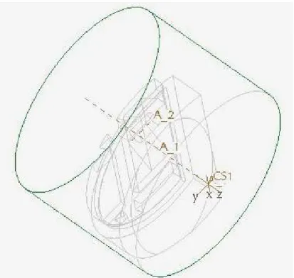
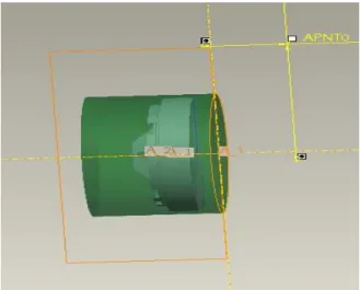
Second we have to define the orientation of the axes: in the COORDINATE SYSTEM window pick the Orientation panel. Define the Z-axis so, that it has to be parallel with the revolution axis of the part, Figure 4-5.
Close the COORDINATE SYSTEM window by picking the OK button in it.
To define this coordinate system as a machining coordinate system, pick the arrow icon near the ‘Machine Zero’ in the OPERATION SETUP window. When the Select popup menu appears, pick to the coordinate system created a moment ago, on the model. Close the OPERATION SETUP window by picking the OK button in it.
6
Figure 4 .The orientation of the NC machine coordinate system.
Figure 5. The orientation of the NC machine coordinate system.
7
2.1. NC sequence: 1. Area turning for machining the face plane
9. The icons of the possible turning NC sequences have appeared on the upper horizontal main icon menu.
10. The first NC sequence will be an Area turning sequence so pick the Area Turning icon. The NC SEQUENCE popup menu appears on the right side.
11. Form the SEQ SETUP menu accept the checked options of Tool, Parameters, Tool Motions and select Start and End options as well. These options has to be defined in the followings. Close the menu with Done.
12. The Tool Setup window should appear. Set the tooling parameters as follows:
TOOL Name: Area
TOOL TYPE Turning
ON THE GEOMETRY PANEL:
TOOL_WITH 3
NOSE _RADIUS 0.2
SIDE_ANGLE 125
END_ANGLE 5
SIDE_WIDTH 3.75
ON THE SETTING PANEL:
TOOL_ NUMBER 1
Figure3. 5. The first tool
Before you close the TOOL SETUP window choose APPLY and OK.
8
13
.
The list of the NC Sequence parameters appears. To bring up all parameters required for this sequence type, pick to ALL button above the list. There are default values for a lot of parameters. It is obligatory to give the values only for theparameters where the field is filled by yellow. The most important parameters you can find in the basic list. Enter the parameters as shown below. (Verify the parameter of CUT_ANGLE which has to be 90 at this NC sequence of the face turning.)
TOOL_ID AREA NCL_FILE - PRE_MACHINING_FILE - POST_MACHINING_FILE -
ROUGH_OPTION ROUGH_ONLY SCAN_TYPE TYPE_1_CONNECT STEPOVER_ADJUST YES
TRIM_TO_WORKPIECE NO
CUT_DIRECTION STANDARD CORNER_FINISH_TYPE FILLET OUTPUT_POINT CENTER GOUGE_AVOID_TYPE TIP_ONLY STEP_DEPTH 1
MIN_STEP_DEPTH - TOOL_CLEARANCE - END_STEP_DEPTH - TOLERANCE 0.01 NUMBER_PASSES 0 NUM_PROF_PASSES 1 PROF_INCREMENT 0 PROF_STOCK_ALLOW 0 ROUGH_STOCK_ALLOW 0 CUT_ANGLE 90 Z_STOCK_ALLOW - START_OVERTRAVEL 0 END_OVERTRAVEL 0 CORNER_LENGTH - CHAMFER_DIM - CORNER_ANGLE - CONCAVE_RADIUS - CONVEX_RADIUS - BACK_CLEAR_ANGLE 5 CUT_FEED 75 ARC_FEED - FREE_FEED - RETRACT_FEED - CUT_UNITS MMPM RETRACT_UNITS MMPM SPINDLE_SPEED 800 SPINDLE_SENSE CW
MAX_SPINDLE_RPM -
SPEED_CONTROL CONST_RPM SPINDLE_RANGE NO_RANGE RANGE_NUMBER 0
CIRC_INTERPOLATION ARC_ONLY NUMBER_OF_ARC_PTS 1
9
COOLANT_OPTION OFF COOLANT_PRESSURE NONE CUTCOM OFF NUMBER_CUTCOM_PTS 1 CUTCOM_LOC_APPR - CUTCOM_LOC_EXIT - CUTCOM_REGISTER - FIXT_OFFSET_REG -
COORDINATE_OUTPUT MACHINE_CSYS TOOL_ORIENTATION 90
END_STOP_CONDITION NONE OSETNO_VAL - Z_GAUGE_OFFSET - X_GAUGE_OFFSET - PLUNGE_FEED - PLUNGE_UNITS MMPM LEAD_RADIUS 0 TANGENT_LEAD_STEP 0 NORMAL_LEAD_STEP 0 RETRACT_RATIO 1.1 PLUNGE_ANGLE 0 PULLOUT_ANGLE 0 APPROACH_DISTANCE - EXIT_DISTANCE -
RETRACT_CONTROL NORMAL_TO_CUT ENTRY_ANGLE 90
EXIT_ANGLE 90 START_MOTION DIRECT END_MOTION DIRECT
After the parameters have been entered, close the list with OK.
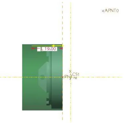
14. Now we define the start tool position. The DEF START menu is active. Since there are no datum points on the models, we have to create one. Pick to the datum point icon on the right side icon menu and the DATUM POINT window appears. Pick in the ‘References’ field and pick inside the datum plane which is equal to the xz plane.
The new point appears on the model as it can be seen in Figure 6. Click in the ‘Offset reference’ field and select a horizontal and a vertical reference on the model: e.g. the A1 axis and the vertical plane (the circle boundary plane) on the workpiece (keep press the Ctrl button on the keyboard for the selection of more than one reference).
Enter the distances of the point from the references: 30 and 15. It is important that the distance of 30mm is in the direction of the positive x axis, since the tool start to move in the positive xz plane. In the end pick OK.
15. Second we define the end tool positions. From the DEF END the Select option is active. Select (pick to) the same point we created a moment ago on the model.
10
Figure 6. Start and End tool position
16. In the TOOL Motion window we define the boundary surface of the material what we will remove from the workpiece in this NC sequence. It will be enough to show it by only a line (by a Turn profile) in the xz plane this boundary. Keep the default options of <end of tool path> and Area Turning Cut. Select insert and the AREA Turning Cut window appears. The Turn profile has to be defined. Pick the Turn Profile icon on the right side, vertical icon menu (perhaps it is hidden by the AREA Turning Cut window, so this should be moved).
The icon menu of the Turn profile command appears below the upper horisontal main icon menu. As the default option (Create an envelope on-the-fly), the system sign a boundary network with yellow colour. Select the Use sketch to define turn profile icon, and then Define an internal sketch icon. The SKETCH window appears, keep the default options and pick Sketch. The system revolves the model into the xz plane.
Select appropriate references for sketching and sketch the only line shown in Figure 7, left. (Draw a line from up to the centre line along the boundary edge of the reference model as it can be seen in Fig 7, left). Close the sketcher (with
icon).The system shows the removable material with the horizontal yellow arrow. If this arrow shows inside the model, pick to it in order to reverse it. Close the Turn profile icon menu withthe green
icon (above, on the right).Activate the Area Turning Cut window by picking the left bottom arrow icon in it, and close it with the green
icon.Close the Tool motion window OK.
17. In the last step of this NC sequence we see the simulation of the tool motion .There are two possibilities. First select Play path on the NC SEQUENCE menu after that select Screen play. See the simulation and the tool path (as it can be seen in Fig. 7, right), click to Close. Second select Play path again, after that select NC Check. In a new VERICUT application we can see the simulation.
Close the NC SEQUENCE menu with DONE Seq.
11
Figure7 . Left: defining the boundary of the material which will be removed.
Right: Tool path of the first NC Sequence
18. We remove the machined material from the model: from the main Insert menu select Material removal cut, and the list of the defined NC sequences appears. Select the 1:Area turning from the list (now there is only this option), select Automatic and Done. The Intersected comps window appears. Select Auto Add and the file name of the workpiece model appears in the upper field, which means that material will be removed from this model. Select OK. The model appears without the removed material.
2.2. NC sequence: 2. Area Sequence for turning the profile
19. The second NC sequence will be an Area turning sequence again, so pick the Area Turning icon on the upper horizontal main manufacturing icon menu. The NC SEQUENCE popup menu appears on the right side.
20. Form the SEQ SETUP menu accept the checked options of Tool, Parameters, Tool Motions and select Start and End options, as well. These options have to be defined in the followings. Close the menu with Done.
21
.
The Tool Setup window should appear. Accept the first tool with OK (we use the same tool as in the last NC sequence).22
.
The list of the NC Sequence parameters appears. To bring up all parameters required for this sequence type, pick to ALL button above the list. Enter the parameters as12
shown below. (Verify the parameter of CUT_ANGLE which has to be 0 at this NC sequence of the profile turning.)
TOOL_ID AREA NCL_FILE - PRE_MACHINING_FILE - POST_MACHINING_FILE -
ROUGH_OPTION ROUGH_ONLY SCAN_TYPE TYPE_1_CONNECT STEPOVER_ADJUST YES
TRIM_TO_WORKPIECE NO
CUT_DIRECTION STANDARD CORNER_FINISH_TYPE FILLET OUTPUT_POINT CENTER GOUGE_AVOID_TYPE TIP_ONLY STEP_DEPTH 1
MIN_STEP_DEPTH - TOOL_CLEARANCE - END_STEP_DEPTH - TOLERANCE 0.01 NUMBER_PASSES 0 NUM_PROF_PASSES 1 PROF_INCREMENT 0 PROF_STOCK_ALLOW 0 ROUGH_STOCK_ALLOW 0 CUT_ANGLE 0 Z_STOCK_ALLOW - START_OVERTRAVEL 0 END_OVERTRAVEL 0 CORNER_LENGTH - CHAMFER_DIM - CORNER_ANGLE - CONCAVE_RADIUS - CONVEX_RADIUS - BACK_CLEAR_ANGLE 5 CUT_FEED 75 ARC_FEED - FREE_FEED - RETRACT_FEED - CUT_UNITS MMPM RETRACT_UNITS MMPM SPINDLE_SPEED 800 SPINDLE_SENSE CW
MAX_SPINDLE_RPM -
SPEED_CONTROL CONST_RPM SPINDLE_RANGE NO_RANGE RANGE_NUMBER 0
CIRC_INTERPOLATION ARC_ONLY NUMBER_OF_ARC_PTS 1
COOLANT_OPTION OFF COOLANT_PRESSURE NONE CUTCOM OFF NUMBER_CUTCOM_PTS 1 CUTCOM_LOC_APPR - CUTCOM_LOC_EXIT -
13
CUTCOM_REGISTER - FIXT_OFFSET_REG -
COORDINATE_OUTPUT MACHINE_CSYS TOOL_ORIENTATION 90
END_STOP_CONDITION NONE OSETNO_VAL - Z_GAUGE_OFFSET - X_GAUGE_OFFSET - PLUNGE_FEED - PLUNGE_UNITS MMPM LEAD_RADIUS 0 TANGENT_LEAD_STEP 0 NORMAL_LEAD_STEP 0 RETRACT_RATIO 1.1 PLUNGE_ANGLE 0 PULLOUT_ANGLE 0 APPROACH_DISTANCE - EXIT_DISTANCE -
RETRACT_CONTROL NORMAL_TO_CUT ENTRY_ANGLE 90
EXIT_ANGLE 90 START_MOTION DIRECT END_MOTION DIRECT
After the parameters have been entered, close the list with OK.
23. We are defining the start and end tool positions. For requiring of the DEF START, second the DEF END menu select the same point we created in the first NC Sequence on the model .
24. In the TOOL Motion window we define the boundary surface of the material what we will remove from the workpiece in this NC sequence. It will be enough to show it by only a line (by a Turn profile) in the xz plane. Keep the default options of <end of tool path> and Area Turning Cut. Select insert and the AREA Turning Cut window appears.
The Turn profile has to be defined. Pick the Turn Profile icon on the right side, vertical icon menu (perhaps it is hidden by the AREA Turning Cut window, so this should be moved).
The icon menu of the Turn profile command appears below the upper horizontal main icon menu. As the default option (Create an envelope on-the-fly), the system sign a boundary network with yellow colour. Select the Use sketch to define turn profile icon, and then the Define an internal sketch icon. The SKETCH window appears, keep the default options and pick Sketch. The system revolves the model into the xz plane.
Select appropriate references for sketching and sketch the only line shown in Figure 8.
(Draw a line from right left along the boundary edge of the reference model as it can be seen in Fig 8). Close the sketcher (with
icon).The system shows the removable material with the vertical yellow arrow. If this arrow shows inside the model, pick to it in order to reverse it. Close the Turn profile icon menu withthe green
icon (above, on the right).14
Activate the Area Turning Cut window by picking the left bottom arrow icon in it. If the field of Turn profile is empty, pick to the Turn profile created a moment ago.
Select Positive Z for the Start extension and Positive X for the End Extension.
Close the Area Turning Cut window with the green
icon.Close the Tool motion window OK.
Figure 8. Boundary edge for the material removing in the second NC Sequence
25. In the last step of this NC Sequence we verify the simulation of the tool motion. First select Play path on the NC SEQUENCE menu, after that select Screen play. See the simulation and click to Close. Second select Play path again after that select NC Check. In the VERICUT application we can play the simulation.
Close the NC SEQUENCE menu with Done Seq.
26. We remove the machined material from the model: from the main Insert menu select Material removal cut, and the list of the defined NC sequences appears. Select the 2:Area turning from the list (now there are two options on the NC SEQ LIST), select Automatic and Done. The Intersected comps window appears. Select Auto Add and the file name of the workpiece model appears in the upper field, which means that material will be removed from this model. Select OK. The model appears without the removed material.
15 T
Figure 9. The tool path of the second NC Sequence
2.3.
3. NC sequence: 1.Groove Sequence
27. In the Model Tree (left side of the screen) we can see how the new manufacturing entities are building after each other. The upper horizontal main manufacturing icon menu is active.
28. To start the 3. sequence choose Groove Turning from the upper horizontal main manufacturing icon menu. The NC SEQUENCE popup menu appears on the right side.
29. From the SEQ SETUP menu select the options of Tool, Parameters, Tool Motions, Start and End. These options have to be defined in the followings. Close the menu with Done.
30
.
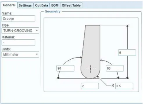
The Tool Setup window should appear. Set the tooling parameters as follows:TOOL_ID Groove
TOOL_TYPE Turn-Grooving
ON THE GEOMETRY PANEL:
16
TOOL_WITH 2
LENGTH 6
NOSE _RADIUS 0.5
SIDE_ANGLE 90
END_ANGLE 90
ON THE SETTING PANEL:
TOOL_ NUMBER 2
Figure 10. The Turn-Grooving tool
To close the TOOL SETUP window choose APPLY and OK.
31. The list of the NC Sequence parameters appears. To bring up all parameters required for this sequence type, pick to ALL button above the list. Enter the parameters as shown below.
TOOL_ID GROOVE NCL_FILE - PRE_MACHINING_FILE - POST_MACHINING_FILE -
ROUGH_OPTION ROUGH_&_PROF SCAN_TYPE TYPE_1
STEPOVER_ADJUST YES TRIM_TO_WORKPIECE NO
CUT_DIRECTION STANDARD CORNER_FINISH_TYPE FILLET OUTPUT_POINT CENTER
17
GROOVE_FINISH_TYPE NO_BACKCUT TOLERANCE 0.01
STEP_OVER 1.5 NUMBER_PASSES 0 NUM_PROF_PASSES 1 PROF_INCREMENT 0 PROF_STOCK_ALLOW 0 ROUGH_STOCK_ALLOW 0 Z_STOCK_ALLOW - SIDEWALL_OFFSET - PECK_DEPTH 0
DEEP_GROOVE_OPTION BY_DEPTH CUT_FEED 75
ARC_FEED - FREE_FEED - RETRACT_FEED - CUT_UNITS MMPM RETRACT_UNITS MMPM SPINDLE_SPEED 800 SPINDLE_SENSE CW MAX_SPINDLE_RPM -
SPEED_CONTROL CONST_RPM SPINDLE_RANGE NO_RANGE RANGE_NUMBER 0
CIRC_INTERPOLATION ARC_ONLY NUMBER_OF_ARC_PTS 1
COOLANT_OPTION OFF COOLANT_PRESSURE NONE CUTCOM OFF NUMBER_CUTCOM_PTS 1 CUTCOM_LOC_APPR - CUTCOM_LOC_EXIT - CUTCOM_REGISTER - CUTCOM_REG_RIGHT - FIXT_OFFSET_REG -
COORDINATE_OUTPUT MACHINE_CSYS DELAY -
TOOL_ORIENTATION 90 END_STOP_CONDITION NONE OSETNO_VAL - Z_GAUGE_OFFSET - X_GAUGE_OFFSET - ALTERNATE_SIDE_OUTPUT NO ALT_OSETNO_VAL - PLUNGE_FEED - PLUNGE_UNITS MMPM CLEAR_DIST 1 PULLOUT_DIST - FULL_RETRACT_DEPTH 0 LEAD_RADIUS 0 TANGENT_LEAD_STEP 0 NORMAL_LEAD_STEP 0 APPROACH_DISTANCE - EXIT_DISTANCE - ENTRY_ANGLE 90 EXIT_ANGLE 90 START_MOTION DIRECT
18
END_MOTION DIRECT
After the parameters have been entered, exit with OK.
32. We are defining the start and end tool positions. For requiring of the DEF START, second the DEF END menu select the same point we created in the first NC Sequence on the model.
33. In the TOOL Motion window we define the boundary surface of the material what we will remove from the workpiece in this NC sequence. It will be enough to show it by only a line (by a Turn profile) in the xz plane. Keep the default options of <end of tool path> and Area Turning Cut. Select insert and the AREA Turning Cut window appears.
The Turn profile has to be defined. Pick the Turn Profile icon on the right side, vertical icon menu (perhaps it is hidden by the AREA Turning Cut window, so this should be moved).
The icon menu of the Turn profile command appears below the upper horizontal main icon menu. As the default option (Create an envelope on-the-fly), the system sign a boundary network with yellow colour. Select the Use sketch to define turn profile icon, and then the Define an internal sketch icon. The SKETCH window appears, keep the default options and pick Sketch. The system revolves the model into the xz plane.
Select appropriate references for sketching and sketch the line network shown in Figure 11. (Two vertical and one horizontal lines as it can be seen in Fig 11). Close the
sketcher (with
icon).The system shows the removable material with the vertical yellow arrow. If this arrow shows inside the model, pick to it in order to reverse it. Close the Turn profile icon menu withthe green
icon (above, on the right).Activate the Area Turning Cut window by picking the left bottom arrow icon in it. If the field of Turn profile is empty, pick to the Turn profile created a moment ago.
Select Positive X for the Start and for the End Extension.
Close the Area Turning Cut window with the green
icon.Close the Tool motion window OK.
34. In the last step we see the simulations of the tool motion. First select play path on the NC SEQUENCE menu after that select screen play. See the simulation and click to close. Second select play path again after that select NC Check. In new application, in the VERICUT we can see the simulation, Figure12.
19
Figure 11.The edge net (with dark blue colour) for the removing material
Figure 12. The tool path of the 3. NC Sequence
20
35. We remove the machined material from the model: from the main Insert menu select Material removal cut, and the list of the defined NC sequences appears. Select the 3:Groove turning from the list (now there are three options on the NC SEQ LIST), select Automatic and Done. The Intersected comps window appears. Select Auto Add and the file name of the workpiece model appears in the upper field, which means that material will be removed from this model. Select OK. The model appears without the removed material.
2.3. NC sequence: 2. Groove Sequence
36. To start the 4. sequence choose Groove Turning from the upper horizontal main manufacturing icon menu. The NC SEQUENCE popup menu appears on the right side.
37. From the SEQ SETUP menu select the options of Tool, Parameters, Tool Motions, Start and End. These options have to be defined in the followings. Close the menu with Done.
38
.
The Tool Setup window should appear. Set the tooling parameters as follows:TOOL_ID Groove2
TOOL_TYPE Turn-Grooving
ON THE GEOMETRY PANEL:
TOOL_WITH 1
LENGTH 4
NOSE _RADIUS 0.5
SIDE_ANGLE 90
END_ANGLE 90
ON THE SETTING PANEL:
TOOL_ NUMBER 3
To close the TOOL SETUP window choose APPLY and OK.
39. The list of the NC Sequence parameters appears. To bring up all parameters required for this sequence type, pick to ALL button above the list. Enter the parameters as shown below.:
TOOL_ID GROOVE2 NCL_FILE -
PRE_MACHINING_FILE - POST_MACHINING_FILE -
ROUGH_OPTION ROUGH_ONLY SCAN_TYPE TYPE_1 STEPOVER_ADJUST YES TRIM_TO_WORKPIECE NO
21
CUT_DIRECTION STANDARD CORNER_FINISH_TYPE FILLET OUTPUT_POINT CENTER GROOVE_FINISH_TYPE NO_BACKCUT TOLERANCE 0.01
STEP_OVER 1 NUMBER_PASSES 0 NUM_PROF_PASSES 1 PROF_INCREMENT 0 PROF_STOCK_ALLOW 0 ROUGH_STOCK_ALLOW 0 Z_STOCK_ALLOW - SIDEWALL_OFFSET - PECK_DEPTH 0
DEEP_GROOVE_OPTION BY_DEPTH CUT_FEED 75
ARC_FEED - FREE_FEED - RETRACT_FEED - CUT_UNITS MMPM RETRACT_UNITS MMPM SPINDLE_SPEED 800 SPINDLE_SENSE CW MAX_SPINDLE_RPM -
SPEED_CONTROL CONST_RPM SPINDLE_RANGE NO_RANGE RANGE_NUMBER 0
CIRC_INTERPOLATION ARC_ONLY NUMBER_OF_ARC_PTS 1
COOLANT_OPTION OFF COOLANT_PRESSURE NONE CUTCOM OFF NUMBER_CUTCOM_PTS 1 CUTCOM_LOC_APPR - CUTCOM_LOC_EXIT - CUTCOM_REGISTER - CUTCOM_REG_RIGHT - FIXT_OFFSET_REG -
COORDINATE_OUTPUT MACHINE_CSYS DELAY -
TOOL_ORIENTATION 90 END_STOP_CONDITION NONE OSETNO_VAL - Z_GAUGE_OFFSET - X_GAUGE_OFFSET - ALTERNATE_SIDE_OUTPUT NO ALT_OSETNO_VAL - PLUNGE_FEED - PLUNGE_UNITS MMPM CLEAR_DIST 1 PULLOUT_DIST - FULL_RETRACT_DEPTH 0 LEAD_RADIUS 0 TANGENT_LEAD_STEP 0 NORMAL_LEAD_STEP 0 APPROACH_DISTANCE - EXIT_DISTANCE -
22
ENTRY_ANGLE 90 EXIT_ANGLE 90 START_MOTION DIRECT END_MOTION DIRECT
After the parameters have been entered, exit with OK.
40. We define the start and end tool positions. Select twice the same point we created in the first NC Sequence in the model .
41. In the TOOL Motion select insert and the AREA Turning Cut window appears. The Turn profile has to be defined. Pick the Turn Profile icon on the right side, vertical icon menu (perhaps it is hidden by the AREA Turning Cut window, so this should be moved).
The icon menu of the Turn profile command appears below the upper horizontal main icon menu. As the default option (Create an envelope on-the-fly), the system sign a boundary network with yellow colour. Select the Use sketch to define turn profile icon, and then the Define an internal sketch icon. The SKETCH window appears, keep the default options and pick Sketch. The system revolves the model into the xz plane.
Select appropriate references for sketching and sketch the line network shown in Figure 13. (A vertical line and a half circle as it can be seen in Fig 13). Close the sketcher (with
icon).The system shows the removable material with the vertical yellow arrow. If this arrow shows right, pick to it in order to reverse it. Close the Turn profile icon menu withthe green
icon (above, on the right).Activate the Area Turning Cut window by picking the left bottom arrow icon in it. If the field of Turn profile is empty, pick to the Turn profile created a moment ago.
Select Positive X for the Start and for the End Extension.
Close the Area Turning Cut window with the green
icon.Close the Tool motion window OK.
42. In the last step we see the simulations of the tool motion. First select play path on the NC SEQUENCE menu after that select screen play. See the simulation and click to close. Second select play path again after that select NC Check. In new application, in the VERICUT we can see the simulation, Figure14.
43. It is not needed to remove the machined material from the model at this NC Sequence, since it does not influence the next tool path. If you intend to do it: from the main Insert menu select Material removal cut, and the list of the defined NC sequences appears. Select the 4:Groove turning from the list (now there are four options on the NC SEQ LIST), select Automatic and Done. The Intersected comps window appears.
Select Auto Add and the file name of the workpiece model appears in the upper field, which means that material will be removed from this model. Select OK. The model appears without the removed material.
23
Figure 13. The boundary edge for the removing material
Figure 14. Tool path of the 4.NC Sequence
2.5. MACHINING SIMULATION
Every NC sequence has been created for the first turning operation. In the following steps we will create the machining simulation of the first operation.
24
44. From the main Edit menu choose CL Data, and Output. The SELECT FEAT menu appears on the right side. Select Operation, OP_010, File, Done. Enter the name of the CL Data file (e.g. Turning). Close the popup menus.
45. From the main Tools menu choose CL Data, Material Removal Simulation, select the name of the CL Data file created a moment ago. Choose Done. In the VERICUT application we can see the full turning simulation.
46. Close the popup windows and menus and save the work.
3. SECOND OPERATION
47. We are now going to start the second operation for this manufacturing model. An operation corresponds to a setup or tape file. We will need to turn over the model on the screen, Figure15. We will need to define new NC machine and Machining coordinate system.
48. In order to start the second operation, choose the Operation from the Steps main menu.
The OPERATION SETUP window should appear. Choose File and New in this window and we get a new, empty surface. The default operation name is “OP020”. We can either accept the name or reenter it e.g.”side2”.
49. NC machine:
To define the NC machine pick to its icon button on the right side of the window, in the line of the ‘NC machine’. The MACHINE TOOL SETUP window should appear.
Choose File and New in this window and we get a new, empty surface. We can accept or modify the Machine Name: the default name is ”Mach02”. For the Machine Type choose MILL on the popup list. Change the Number Of Axes from 3 to 5. To close the MACHINE TOOL SETUP window pick the OK button
50. In the Fixture Setup option we can define the model of the fixture. An assembly containing the fixture can be created. This step is not essential to generate NC programs, so we not show it here in this example.
51. Machine Zero (machine coordinate system):
The system requires the machine coordinate system and you can create it here, as well.
To define the coordinate system, pick the arrow icon near the Machine Zero in the OPERATION SETUP window.
Pick the coordinate system icon in the main window, on the right side vertical icon menu. The COORDINATE SYSTEM window should appear. Pick inside the field of the ‘References’ and show references for our coordinate system as follows:
For example: select three perpendicular planes e.g. DTM1, DTM2 and DTM3 datum planes on the workpiece (pick on them on the model, press the Ctrl button on the keyboard and keep it press during the selections). In this case the intersect point of the planes will be the origin and the intersect lines of the planes will be the axes of the coordinate system as you can see on the screen.
25
Second we have to define the orientation of the axes: in the COORDINATE SYSTEM window pick the Orientation panel. Define the Z-axis so, that it has to be parallel with the axis of the hole of the design part, see Figure 15. (From the positive Z-axis the tool starts to cut during NC milling.)
Close the COORDINATE SYSTEM window by picking the OK button in it.
52. Retract plane
Pick the arrow icon near the „Surface” in the OPERATION SETUP window. The retract selection window should appear. Enter 30 to the Value which means the Z axis depth for the retraction of the tool. Close the window with OK and close the operation setup window with OK.
Figure 15 Machine coordinate system of the second operation
3.1. NC Sequence: Volume Rough
53. New icons for the milling operation have appeared below the main horizontal menu. The first NC sequence will be a Volume Rough milling sequence so pick the Volume Rough icon. The NC SEQUENCE popup menu appears on the right side.
54. In the SEQ SETUP menu, make sure Tool, Parameters and Window are checked, then choose with Done.
26
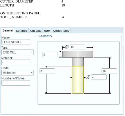
55. The Tool Setup window should appear. Set the tooling parameters as follows and according to Figure 16:
TOOL_ID Flatendmil
TOOL_TYPE END MILL
ON THE GEOMETRY PANEL:
CUTTER_DIAMETER 4
LENGTH 18
ON THE SETTING PANEL:
TOOL_ NUMBER 4
Figure 16: The tool for the Volume Rough NC Sequence
Close the tool Setup window with Apply and OK.
56. The list of the NC Sequence parameters appears. To bring up all parameters required for this sequence type, pick to ALL button above the list. Enter the parameters as they are shown below:
TOOL_ID FLATENDMLL NCL_FILE -
PRE_MACHINING_FILE - POST_MACHINING_FILE -
ROUGH_OPTION ROUGH_ONLY SCAN_TYPE TYPE_3 CUT_TYPE CLIMB STEPOVER_ADJUST YES RETRACT_OPTION OPTIMIZE
27
RETRACT_TRANSITION CORNER_TRANSITION TRIM_TO_WORKPIECE FULL_TRIM
CUT_DIRECTION STANDARD CORNER_FINISH_TYPE FILLET CUSTOMIZE_AUTO_RETRACT YES POCKET_EXTEND TOOL_ON PLUNGE_PREVIOUS NO STEP_DEPTH 1 MIN_STEP_DEPTH - TOLERANCE 0.01 STEP_OVER 2 CORNER_ROUND_RADIUS - TOOL_OVERLAP - NUMBER_PASSES 0 NUM_PROF_PASSES 1 PROF_INCREMENT 0 ROUGH_STOCK_ALLOW 0 PROF_STOCK_ALLOW 0 BOTTOM_STOCK_ALLOW - WALL_SCALLOP_HGT 0 BOTTOM_SCALLOP_HGT 0 AXIS_SHIFT 0 CUT_ANGLE 0 CUT_FEED 75 FREE_FEED - RETRACT_FEED - PLUNGE_FEED - RAMP_FEED - ARC_FEED -
ARC_FEED_CONTROL TOOL_CENTER TRAVERSE_FEED -
CUT_UNITS MMPM RETRACT_UNITS MMPM PLUNGE_UNITS MMPM SPINDLE_SPEED 800 WALL_PROFILE_SPINDLE_SPEED - SPINDLE_SENSE CW
MAX_SPINDLE_RPM -
SPEED_CONTROL CONST_RPM SPINDLE_RANGE NO_RANGE RANGE_NUMBER 0
LINTOL -
CIRC_INTERPOLATION ARC_ONLY NUMBER_OF_ARC_PTS 1
COOLANT_OPTION OFF COOLANT_PRESSURE NONE CUTCOM OFF NUMBER_CUTCOM_PTS 1 CUTCOM_LOC_APPR - CUTCOM_LOC_EXIT - CUTCOM_REGISTER - FIXT_OFFSET_REG -
COORDINATE_OUTPUT MACHINE_CSYS END_STOP_CONDITION NONE
OSETNO_VAL - Z_GAUGE_OFFSET - WALL_PROFILE_CUT_FEED -
28
RAMP_ANGLE 90 CLEAR_DIST 1 PULLOUT_DIST - HELICAL_DIAMETER - LEAD_IN NO LEAD_OUT NO LEAD_RADIUS 0 TANGENT_LEAD_STEP 0 NORMAL_LEAD_STEP 0
APPR_EXIT_PATH TRIM_BOTH APPR_EXIT_HEIGHT DEPTH_OF_CUT APPROACH_DISTANCE -
EXIT_DISTANCE - OVERTRAVEL_DISTANCE 0 APPR_EXIT_EXT 0 ENTRY_ANGLE 90 EXIT_ANGLE 90 START_MOTION DIRECT END_MOTION DIRECT RETRACT_RADIUS -
It is important to verify, that the parameter TRIM_TO_WORKPIECE has to be FULL_TRIM at this NC Sequence.
After the parameters have been modified, exit the parameter tree window by choosing OK.
57. For this sequence we will create a Mill Window. When the DEFINE WIND menu appears choose the Mill Window icon from the right side, vertical icon menu. The Define window plane icon menu appears below the upper horizontal main menu.
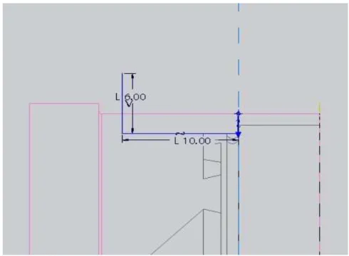
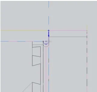
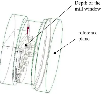
The Mill Window will be created by sketching a rectangle, using the outside edges of the workpiece. The starting plane (sketching plane) will be a plane above the reference model and the depth of the cut will be an internal plane of the model shown in Figure 17.
58. From the Define window plane icon menu select Sketch window type (the middle icon), since we will sketch the region which will be machined.
59. Open the Placement panel (pick to it). A window plane has to be selected. The window plane has to be above the model. Since there is no such plane on the model, we have to create it now. Pick to the Datum plane tool icon from the right side, vertical icon menu. The DATUM PLANE window appears. As a reference select the DTM1 datum plane on the model. Enter the Offset translation of 20 mm. Verify that the new datum plane is above the model. Close the DATUM PLANE window with OK. If the Define window plane icon menu is not active, activate it by picking to the arrow icon on the right side. It is probable, that you need to open again the Placement panel and pick to the new datum plane which will be the starting window plane.
60. We have to define the area (a rectangle) on the new datum plane, since we have to define the region which will be machined. Pick to the Define an internal sketch icon on the Define window plane icon menu. The SKETCH window appears. As a reference select a plane on the model which is perpendicular to the starting window plane (the
29
new datum plane), Fig. 17. Select Sketch in the SKETCH window. Select the appropriate references for the sketching and sketch the rectangle shown in Figure 18.
Close the sketcher.
61. In the end the depth of the Mill window has to be defined. Open the Depth panel on the Define window plane icon menu and sign the Specify the depth. From the Depth options select the To selected option and pick to the internal plane of the manufacturing model as it is shown in Figure 17. Close the Define window plane icon menu with the green
icon.Figure 17. The depth of the mill window and the reference plane for the sketching
Figure 18. The Internal sketch of the Mill window Sketch the pink rectangle Depth of the mill window
reference plane
30 .
62. In the last step we see the simulations of the tool motion. First select play path on the NC SEQUENCE menu after that select screen play. Play the simulation and click to close. Second select play path again after that select NC Check. In new application, in the VERICUT we can see the simulation. The model is shown in Figure 19 after the machining.
Figure19. The model after the volume milling
63. In order to remove the material from the model, select Material removal cut from the main Insert menu, and the list of the defined NC sequences appears. Select the 1:Volume milling from the list, select Automatic and Done. The Intersected comps window appears. Select Auto Add and the file name of the workpiece model appears in the upper field, which means that material will be removed from this model. Select OK.
The model appears without the removed material.
31
3.2. NC Sequence: Trajectory milling
In this NC Sequence the linear groove at the neck will be cut. The Trajectory milling type of NC sequence will be used. It is characteristic that there is no tool path computation at this NC sequence, the toll path is sketched.
64. The second NC sequence will be a Trajectory milling sequence so pick the Trajectory icon. For the number of the machining axes accept the default 3 Axis option and close the MACH AXES menu with Done. The NC SEQUENCE popup menu appears on the right side.
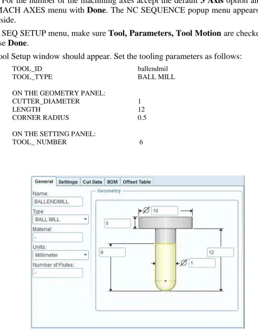
65. In the SEQ SETUP menu, make sure Tool, Parameters, Tool Motion are checked, then choose Done.
66.The Tool Setup window should appear. Set the tooling parameters as follows:
TOOL_ID ballendmil
TOOL_TYPE BALL MILL
ON THE GEOMETRY PANEL:
CUTTER_DIAMETER 1
LENGTH 12
CORNER RADIUS 0.5
ON THE SETTING PANEL:
TOOL_ NUMBER 6
Figure 20. The tool for the Trajectory milling
We close the tool Setup window with Apply and OK.
32
67. The list of the NC Sequence parameters appears. To bring up all parameters required for this sequence type, pick to ALL button above the list. Enter the parameters as they are shown below:
CUT_FEED 75 SPINDLE_SPEED 800 CLEAR_DIST 1
After the parameters have been modified, exit the parameter tree window by choosing OK.
68. The Tool Motions window appears. Choose Insert and the Curve Trajectory Setup window appears. Now we have to show the curve of the tool path. Since we do not have such curve, we will create it here. Select the Sketch tool from the right side, vertical main icon menu. The sketch window appears. For the Sketching plane select the plane signed with red colour in Figure 21 and for the reference plane select the perpendicular plane.
Select appropriate references for the sketching and sketch the line according to Figure 22.
It has to be mentioned that this line is at the bottom of the groove.
Close the sketcher and activate the Curve Trajectory Setup window if it is needed. (For the activation pick to the arrow icon bottom in the window.) Select Left for Tool Offset and verify that the offset arrow shows inside the groove. Close the Curve Trajectory Setup window with OK.
Close the Tool Motions window with OK.
Figure 21. Definition of the new datum plane Reference plane
33
Figure 22 Definition of the trajectory
69. Select play path on the NC SEQUENCE menu after that select screen play. Play the simulation and click to close. Second select play path again after that select NC Check.
In new application, in the VERICUT we can see the simulation. The model is shown in Figure 23 after the machining.
34
Figure 23. Tool path of the trajectory NC Sequence
3.3. NC Sequence: Holemaking
70. The third NC sequence will be a Holemaking sequence so pick the Insert a drilling cycle icon and select Standard. For the number of the machining axes accept the default 3 Axis option and close the MACH AXES menu with Done. The NC SEQUENCE popup menu appears on the right side.
71. In the SEQ SETUP menu, make sure Tool, Parameters, Holes are checked, then choose Done.
72. The Tool Setup window appears. Set the tooling parameters as follows:
TOOL_ID DRILLING
TOOL_TYPE DRILLING
ON THE GEOMETRY PANEL:
CUTTER_DIAMETER 3
35
LENGTH 12
POINT ANGLE 118
ON THE SETTING PANEL:
TOOL_ NUMBER 7
Figure 24: Tool for the drilling
We close the Tool Setup window with Apply and OK.
73. The list of the NC Sequence parameters appears. To bring up all parameters required for this sequence type, pick to ALL button above the list. Enter the parameters as they are shown below:
CUT_FEED 75 SPINDLE_SPEED 800 CLEAR_DIST 1
After the parameters have been modified, exit the parameter tree window by choosing OK.
74. The hole set window appears. To define the Depht accept the option of Auto for the Start option, and enter 7 (mm) for the End option.
For the Hole axes Set select the axis (A-2) of the hole of the design model.
Close the Hole Set window with the green
icon.36
The tool path definition is ready as it is shown in the figure 25. We can play the simulation as we have done it in the previous NC Sequences. We close the new NC Sequence with Done Seq.
Figure 25: Tool path of the holemaking
3.4. NC Sequence: Surface milling
75. The fourth NC sequence will be a Surface Milling sequence so pick the Surface Milling icon. For the number of the machining axes choose 5 Axis option and close the MACH AXES menu with Done. The NC SEQUENCE popup menu appears on the right side.
37
76. In the SEQ SETUP menu, make sure Tool, Parameters, Surfaces, Define cut are checked, then choose Done.
77. The Tool Setup window should appear. Set the tooling parameters as follows:
TOOL_ID BALLENDMILL2
TOOL_TYPE BALL MILL
ON THE GEOMETRY PANEL:
CUTTER_DIAMETER 3
LENGTH 12
CORNER RADIUS 1.5
ON THE SETTING PANEL:
TOOL_ NUMBER 8
Figure 26: Tool for the Surface Milling
We close the tool Setup window with Apply and OK.
78. The list of the NC Sequence parameters appears. To bring up all parameters required for this sequence type, pick to ALL button above the list. Enter the parameters as they are shown below:
CUT_FEED 75
STEP_OVER 1
SPINDLE_SPEED 800 CLEAR_DIST 1
After the parameters have been modified, exit the parameter tree window by choosing OK.
38
79. The SURF PICK menu appears. Select the Model option and Done. Click to the surface which we will machine as it is shown in Figure 27.
Figure 27. The surface to be machined
Select Done Return for the SELECT SRFS menu and again Done Return for the NCSEQ SURFS menu.
The Cut Definition window appears. Select From surface isolines option from the upper list. Pick to the selected surface on the surface list (surface Id = 464). The cut direction has to be horizontally. Verify it with the arrow icon (left, bottom in the Cut Definition window): pick to this icon while the yellow arrow is not horizontal (on the model).
Choosing Preview we can see the tool slices. Close the Cut Definition window with OK.
The tool path definition is ready as it is shown in the Figure 28. We can play the simulation as we have done it in the previous NC Sequences. We close the new NC Sequence with Done Seq.
39
Figure 28: The tool path of the surface milling
3.5. MACHINING SIMULATION
Every NC sequence has been created for the second, milling operation. In the following steps we will create the machining simulation of this operation.
80. From the main Edit menu choose CL Data, and Output. The SELECT FEAT menu appears on the right side. Select Operation, OP_020, File, Done. Enter the name of the CL Data file (e.g. Milling1). Close the popup menus.
81. From the main Tools menu choose CL Data, Material Removal Simulation, select the name of the CL Data file created a moment ago. Choose Done. In the VERICUT application we can see the full turning simulation.
82. Close the popup windows and menus and save the work.
40
4. THIRD OPERATION
During the third operation the rest material will be removed from the workpiece. It is assumed that the material is cut to the top plane of the model shown in Figure 29.
83. In order to start the second operation, choose the Operation from the Steps main menu.
The OPERATION SETUP window should appear. Choose File and New in this window and we get a new, empty surface. The default operation name is “OP030”. We can either accept the name or reenter it e.g.”side3”.
84. NC machine:
To define the NC machine pick to its icon button on the right side of the window, in the line of the ‘NC machine’. The MACHINE TOOL SETUP window should appear.
Choose File and New in this window and we get a new, empty surface. We can accept or modify the Machine Name: the default name is ”Mach03”. For the Machine Type choose MILL on the popup list. To close the MACHINE TOOL SETUP window pick the OK button.
85. In the Fixture Setup option we can define the model of the fixture. An assembly containing the fixture can be created. This step is not essential to generate NC programs, so we not show it here in this example.
86. Machine Zero (machine coordinate system):
To define the coordinate system, pick the arrow icon near the Machine Zero in the OPERATION SETUP window.
Pick the coordinate system icon in the main window, on the right side vertical icon menu. The COORDINATE SYSTEM window should appear. Pick inside the field of the ‘References’ and show references for our coordinate system as follows:
For example: select three perpendicular planes e.g. DTM1, DTM2 and DTM3 datum planes on the workpiece (pick on them on the model, press the Ctrl button on the keyboard and keep it press during the selections).
Second we have to define the orientation of the axes: in the COORDINATE SYSTEM window pick the Orientation panel. Define the Z-axis so, as it can be seen in Figure 29.
(From the positive Z-axis the tool starts to cut during NC milling.)
Close the COORDINATE SYSTEM window by picking the OK button in it.
87. Retract plane
Pick the arrow icon near the „Surface” in the OPERATION SETUP window. The retract selection window should appear. Enter 40 to the Value which means the Z axis depth for the retraction of the tool. Close the window with OK and close the operation setup window with OK..
41
Figure 29.The machine coordinate system of the third operation
4.1. NC Sequence: Volume milling
88. To start the sequence, choose the Volume Rough from the manufacturing icon menu (below the main upper horizontal menu).
89. In the SEQ SETUP menu, verify that Tool, Parameters, Window are checked, then choose Done.
90.The Tool Setup window appears. Select File, Use previous .From the tool list select the first tool of the Volume Milling sequence of the second operation and select OK.
(We use the same tool which we defined in our previous Volume milling NC sequence.)
Close the tool Setup window with OK.
91. On the MFG PARAMS list enter the parameters as shown below:
TOOL_ID FLATENDMLL ROUGH_OPTION ROUGH_ONLY SCAN_TYPE TYPE_3 TRIM_TO_WORKPIECE FULL_TRIM STEP_DEPTH 1
STEP_OVER 2 CUT_FEED 75 SPINDLE_SPEED 800 CLEAR_DIST 1
42
It is important to verify, that the parameter TRIM_TO_WORKPIECE has to be FULL_TRIM at this NC Sequence.
Close the tool parameter list with OK.
92. For this NC sequence we will create a Mill Window. When the DEFINE WIND menu appears choose the Mill Window icon from the right side, vertical icon menu. The Define window plane icon menu appears below the upper horizontal main menu.
The Mill Window will be created by sketching an area, using the outside edges of the workpiece. The starting plane (sketching plane) will be the top plane of the workpiece model and the depth of the cut will be an internal plane of the model shown in Figure 30.
93. From the Define window plane icon menu select Sketch window type (the middle icon), since we will sketch the region which will be machined.
94. Open the Placement panel (pick to it). A window plane has to be selected. The window plane (sketching plane) has to be the top plane of the workpiece model. Pick to it, Fig. 30.
Sketching plane Depth
plane
Figure 30. Sketching planes and the depth of the Mill Window
95. We have to define the area on the window plane, since we have to define the region which will be machined. Pick to the Define an internal sketch icon on the Define window plane icon menu. The SKETCH window appears. Pick Sketch in the SKETCH window. Select the appropriate references for the sketching and use the boundary edges of the workpiece model for the sketching as it is shown in Figure 31.
Close the sketcher.
43
Figure 31. For the extrude selection
96. In the end the depth of the Mill window has to be defined. Open the Depth panel on the Define window plane icon menu and sign the Specify the depth. From the Depth options select the To selected option and pick to the internal plane of the manufacturing model as it is shown in Figure 30. Close the Define window plane icon menu with the green
icon.97. The NC sequence has now been set up. Choose Play Path, Done to view a tool path similar to what is shown in figure 32. Choose Done Seq from the NC SEQUENCES menu and save the work.
Sketch the red
boundary
44
Figure 32. Tool path of the VOLUME MILLING
4.2. NC Sequence: 1. Trajectory milling
98. To start the NC sequence choose Trajectory and Done. For the number of the machining axes accept the default 3 Axis option and close the MACH AXES menu with Done. The NC SEQUENCE popup menu appears on the right side.
99. In the SEQ SETUP menu, make sure Tool, Parameters and Tool Motions are checked, then choose Done.
100. The Tool Setup window should appear. We use the same tool as was used in the last NC Sequence: from the tool list select the first tool named FLATENDMILL and select OK.
101. On the MFG parameter list enter the parameters as shown below:
CUT_FEED 75 SPINDLE_SPEED 800 CLEAR_DIST 1
Close the MFG PARAMS list with OK.
45
102. The Tool Motions window appears. Choose Insert and the Curve Trajectory Setup window appears. Now we have to show the curve of the tool path, we will sketch it here. Select the Sketch tool from the right side, vertical main icon menu. The sketch window appears. For the Sketching plane select the bottom plane of the grooves of the reference model and for the reference plane select a perpendicular plane, Figure 33.
Select appropriate references for the sketching and sketch the line net according to Figure 34.
Close the sketcher and activate the Curve Trajectory Setup window if it is needed.
(For the activation pick to the arrow icon bottom in the window.) Select None for Tool Offset, the trajectory is not needed to move here. Close the Curve Trajectory Setup window with OK.
Close the Tool Motions window with OK.
.
Figure 33. Sketching and reference plane for sketching
103. The NC sequence has now been set up. Choose Play Path, Done to view a path similar what is shown in figure 35. Choose Done Seq from the NC SEQUENCES menu and save the work.
Reference plane
sketching plane
46
Figure 34.The red line net is the trajectory
Figure 35. The trajectory tool path
47
4.3. NC Sequence: Surface milling
104. To start the NC sequence choose Surface Milling and Done. The NC SEQUENCE popup menu appears on the right side.
105. In the SEQ SETUP menu, make sure that Tool, Parameters, Surfaces, Define cut are checked, then choose Done.
106. The Tool Setup window should appear. Define a new tool with the following parameters:
TOOL_ID BALLMILL2
TOOL_TYPE BALL MILL
ON THE GEOMETRY PANEL:
CUTTER_DIAMETER 2
LENGTH 12
ON THE SETTINGs PANEL:
TOOL_ NUMBER 9
Close the Tool Setup window with Apply and OK.
107. From the MFG PARAMS menu, choose Set. Enter the parameters as shown below:
CUT_FEED 75 STEP_OVER 0.5 SPINDLE_SPEED 800 CLEAR_DIST 1
After the parameters have been modified, exit the Param tree window.
108. The Surf pick menu appears. Select the Model option and Done. Pick to the surface which we will machine as it is shown in figure 36. Close the NCSEQ SURF menu with Done Return.
109. The Cut Definition window appears. Select From surface isolines option from the upper list. Pick to the selected surfaces on the surface list. The cut direction has to be horizontally. Verify it with the arrow icon (left, bottom in the Cut Definition window):
pick to this icon while the yellow arrow is not horizontal (on the model). Choosing Preview we can see the tool slices. Close the Cut Definition window with OK.Close the Cut Definition window with OK.
110. The tool path definition is ready as it is shown in the F igure 37. We can play the simulation as we have done it in the previous NC Sequences. We close the new NC Sequence with Done Seq.