Department of Structural Engineering, Faculty of Civil Engineering, Budapest University of Technology and Economics, M}uegyetem rkp. 3, 1111 Budapest, Hungary
Received: November 28, 2019 • Revised manuscript received: April 19, 2020 • Accepted: May 2, 2020 Published online: February 4, 2021
ABSTRACT
This paper presents the results of a theoretical-numerical study of laterally-restrained thin-walled steel rectangular hollow flange beams subjected to bending, shear and bending and shear interaction. Finite element analyses were carried out by using ANSYS software, and validated by previous experimental tests. Furthermore, the effect of intermediate stiffeners was investigated, where the improvement per- centage in bending capacity was 4.4%. Additionally, all the corresponding outcomes were calculated according to EN 1993-1-3. The results showed that current standard rules tend to be somewhat con- servative in both bending and bending and shear interaction cases, while they are not quite accurate in shear case.
KEYWORDS
cold-formed steel profiles, rectangular hollow flange beams, flexural capacity, Shear capacity, bending and shear interaction, numerical modeling
1. INTRODUCTION
Nowadays, Rectangular Hollow Flange Beams (RHFBs) have been used frequently in structures field. For instance, one of their famous applications is LiteSteel Beam (LSB) (Fig. 1), which is a new cold-formed steel beam produced by Onesteel Australian Tube Mills (OATM), made of two torsionally rigid hollowflanges and a slender web [1].
The study of buckling is important and necessary for the design of any facility, but since cold-formed elements are exposed to more complex buckling patterns than hot-rolled steel elements, hence, buckling analyses has become an essential issue in cold-formed section design. Thus, in the last 10 years many experimental tests and research projects have been performed to improve RHFBs behavior and resistance. Many ways of forming and config- urations of cross section were discussed with experimental, numerical and theoretical studies, where buckling behavior and corresponding capacities were observed [2–5]. For example, Jeyaragan and Mahendran [6] showed that LSB segments are prone to many types of collapse when they are exposed to bending, depending on the length of spans. Furthermore, strengthening method of RHFBs have been investigated in many papers, either by using different connecting methods, or web stiffeners and CFRP [7–9].
Since RHFB is a new cross section in cold-formed steel, new structural system will be produced by using these elements. Thus, the design method of Eurocode must be checked for this new system, especially that most of the research projects in this topic is conducted ac- cording to the Australian standards. Hence, the objective of this paper is to apply and verify the available design methods of Eurocode of cold-formed section to typical cold-formed steel rectangular hollow flange beams and to improve the capacity of rectangular hollow flange beams by means of intermediate stiffener.
A numerical model using ANSYS software [10] will be verified by previous tests [2] in Section 2. The next step is to check the bending design value according to Eurocode 3 in Section 3 and compare design values from hand calculationMECc;Rd, numerical model MFEMc;Rd
An International Journal for Engineering and Information Sciences
16 (2021) 1, 58–64
DOI:
10.1556/606.2020.00110
© 2020 The Author(s)
ORIGINAL RESEARCH PAPER
pCorresponding author.
E-mail:nathalie.eid@epito.bme.hu
and test results McTest;Rd together. Furthermore, Section 3 provides details of the improved cross-section analysis by flange intermediate stiffeners, and its bending design values, which are denoted by Mc;RdF;EC;Mc;RdF;FEM, where F refers to flange. In Section 4 the load and boundary conditions of the original numerical model will be modified in order to study shear case instead of pure flexural case. Additionally, the combination between flexural moment and shear will be studied and checked in Section 5. Finally, drawing conclu- sions and recommendation for future research will be done in Section 6. The previous steps are demonstrated inTable 1.
2. NUMERICAL MODEL DEVELOPMENT
A shell finite element model was developed in this section;
using ANSYS software; and validated according to test re- sults obtained from previous experimental research at Trento University, Italy [2]. The tests were carried out on full-scale specimens to investigate the flexural performance of cold-formed thin-walled laterally-restrained steel RHFBs.
2.1. Geometry and material properties
The beam’s span was 4 m, the cross section, which was modeled, is RHFB-300. All specimens were fabricated by welding tubes to web. The averages of the measured di- mensions of the specimens, which are illustrated inTable 2 [2], were the geometry of the modeled section (Fig. 1).
The measured yield strength of the flanges is 394.8 MPa and for the web is 258.5 MPa, the elastic modulus is 203 GPa
[2]. Namely, an elastic-perfectly plastic material model was used here.
2.2. Finite elements
4-node element type shell 181 was used in the model each node has six degrees of freedom. The maximum dimension of any element is 25 mm. Since the failure mode of all specimens did not show any kind of separation between web and flanges, the modeling of welding was not considered.
2.3. Loads and constraints
In detail, a roller and a hinge were modeled at the supports by assigning the relevant condition to all nodes along each edge of the lower flange. In addition, restraints against horizontal displacement were added along the edge of the upper plate of the top flange. Also, the load was applied by imposing increasing four concentrated loads to the top nodes of web stiffeners, located at half meter from the middle of the span (Fig. 2).
2.4. Modeling of initial imperfection
Since the section is restrained against any type of global buckling through boundary conditions, which simulate the real construction; conditions presented by sheathing on both side of section, the observed buckling mode was only local one. The amplitude of the imperfection was selected by following the approach proposed by Schafer and Pek€oz [11]
according to the equation d 5 0.006w, where w is the element width anddrepresents the maximum imperfection amplitude. Furthermore, an imperfection sensitivity analysis was carried out, the results shows that using higher imper- fection amplitudes than the one, which gives the same ul- timate load as in test results gave almost the same ultimate Fig. 1.Left: LiteSteel beams [1], right: Geometry of the tested section, on the basis of [2]
Table 1.Detailed research program
Research program
Section types
O F W
Internal forces M Test, EC, FEM EC, FEM –
V EC, FEM – EC, FEM
MþV EC, FEM EC, FEM –
WhereOis the original cross section;Fis the improved cross section by intermediate stiffeners in theflanges;Wis the improved cross section by intermediate stiffener in the web.
Table 2.Measured section dimensions of the specimens h(mm) b(mm) ct(mm) t(mm)
T04 RHFB-300 298.3 150 30.4 2.87
T05 RHFB-300 296.8 150.1 30.0 2.86
T05 RHFB-300 297.5 150.1 30.2 2.93
F.E. model 297.53 150.067 30.2 2.887
capacity but with difference in the initial stiffness.Figure 2 shows the buckling mode shape of the compressedflange. In detail, the buckling modes were represented by local buck- ling waves distributed on the top of the compressedflange.
The longitudinal wavelength is 180 mm approximately.
Indeed, the main reasons of buckling in RHF profiles are because of the high imperfection amplitude which is resulted by the production process. Thus, developing an exclusive cut machine could reduce the high imperfection problem with good percentage and consequently enhance the section buckling capacity.
2.5. Analysis type
The type of analysis is nonlinear, with assumption of using large deformation. The material model is nonlinear as well (Geometrically and Material Nonlinear Imperfection Anal- ysis (GMNIA)). Thus, multiple load steps to solve the problem were needed.
2.6. Evaluation of the results
Figure 3 shows a comparison of bending moment- displacement curves between test [2] and numerical results.
The figure shows an apparent convergence between the curves. The ultimate moments of the tested beams are 96.0, 97.30, 94.20 kNm for T04, T05, and T06 respectively [2], while it is 101.37 kNm for the numerical result. In thisfigure My.w,My.fmean average elastic moment for web andflanges respectively, Mp means average plastic moment of the specimens computed based on actual geometric and me- chanical properties. Moreover, the mode of failure that
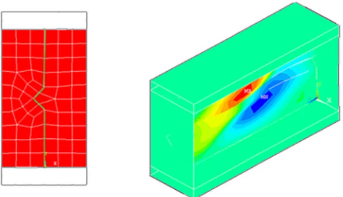
demonstrates the main plastic mechanism on the top com- pressedflange was well captured as it is shown inFig. 4. As a result, the developedfinite element model, which follows the tested beams behavior will be used for further studies.
3. CROSS-SECTION ANALYSIS AND DEVELOPMENT FOR BENDING MOMENT
In subsection 3.1 the design value for original section was calculated according to Eurocode (EC 1993-1-3) [12] and test results [2] were converted to design value according to [12] as well. Moreover, a new numerical model has been performed by using nominal properties in order to define the moment capacity design value of the structure.
Furthermore, a comparison of the previous design values was made. Finally, analysis of the improved cross section by intermediate stiffeners in the flanges was conducted in subsection 3.2 and comparison between the results was demonstrated in subsection 3.3.
3.1. Original section
The effective cross section (Fig. 5) and bending design resistance were determined based on both part 1–3 [12] and part 1–5 [13] of Eurocode 3, by using nominal dimensions Fig. 2.Left: Applied loads and restraint conditions, right: Lowest
local buckling mode shape of the compressedflange
Fig. 3.Experimental [2] and numerical bending moment–
displacement curves
Fig. 4.Failure mode of the beam
Fig. 5.Left: Effective cross section, right: Improved section by intermediate stiffeners in theflanges
according to Table 3 and assuming that the basic yield strength offlange tubes isfyb5355 N/mm2, the basic yield strength of web plate isfyb5235 N/mm2(nominal values of basic yield strength according to table 3.1 b in [12] and partial factorgM0 5 1.0. Hence, the design moment resis- tance is:
MECc;Rd ¼Weff3fyb
gM0 ¼91:90 kNm: (1)
To determine the bending design value from FEM, ðMcFEM;RdÞthe same numerical model, which was discussed in Section 2, was performed but with three differences. Thefirst difference is that the measured values of section dimensions were replaced by nominal values according toTable 3. The second difference is that the measured values of yield strengths were replaced by nominal values, while the third one is the maximum imperfection amplitude, which was taken according to Eurocode, imp¼a=200 where a is the element width. The maximum moment resistance in this case was 98.27 kNm.
In order to compare test results withMc;RdEC andMcFEM;Rd, the design value of test resultsMTestc;Rdwas calculated according to A.6.4 [12] by deriving it from the corresponding charac- teristic valueRk determined by testing, using:
MTestc;Rd ¼hsysRk
gm¼90:94 kNm; (2)
wheregmis the partial factor for resistance; (1.0 for build- ings).hsys is a conversion factor for differences in behavior under test conditions and service conditions (may be taken as 1.0).
The results (Table 4) show clearly that EC 1993 result and adjusted test result according to EC 1993 are almost the same; however, these two values could be somewhat con- servative with reference to the numerical model result of RHFB. Moreover, employing amplitude value according to EC recommendation gives higher resistance, which could be because of this value, has been developed for hot rolled sections; thus, EC recommendation should be improved to use higher imperfection value in case of RHFBs.
3.2. Cross section development for bending
In this subsection the cross section was improved by adding two intermediate stiffeners, one in the middle of the upper part of the top flange and another one in the middle of the lower part of the bottom flange as it is shown inFig. 5. This type of stiffening solution; proposed to refrain local buck- ling, is a feature of the product and it could be considered as an optimized section based on [2]. It is useful to mention here that this kind of section is always found supported by sheathing in construction conditions, thus any kind of global buckling is avoided. Both numerical and theoretical studies of the new cross section were conducted.
A shell finite element model for the optimized cross section has been developed by using nominal dimensions and material grades and 103 10 mm dimensions of inter- mediate stiffeners, wherex3xsymbol is used to determine the stiffener size as it is shown inFig. 5.
The maximum imperfection amplitude was taken here according to Eurocode imp ¼a=200, where a is equal to ð150=2−10¼65 mmÞ.
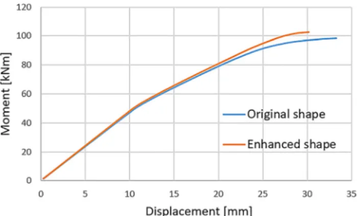
Figure 6 shows a comparison of bending moment- displacement curves between the original cross section and the improved one. The figure shows a small improvement (4.4%) between the two curves. Moreover, the failure mode of the top compressed flange (Fig. 7) was much better in comparison with the original one, where no local buckling
Table 4.Comparison of design values
Design moment value (kNm) Calculated from EurocodeMc;RdEc 91.90 Obtained from test results
adjustmentMc;RdTest
90.94 Obtained from numerical model
with nominal material grades Mc;RdFEM
9,827
Fig. 6.Comparison of bending moment-displacement curves for the original and enhanced cross section by intermediate stiffeners
in theflanges
Fig. 7.Lowest local buckling mode shape of the compressionflange of improved cross section by intermediate stiffeners in theflanges Table 3.Nominal section dimensions of the specimens [2]
h(mm) b(mm) ct(mm) t(mm)
RHFB-300 300 150 30 3
wave’s distribution was observed, but only few small local dents.
On the other hand, the design moment capacity of the improved section was determined by following the steps of Plane elements with intermediate stiffeners calculation [12], and by using nominal geometry and material grades.
The results (Table 5) show a small improvement between the two sections, which is 4.4% according to the numerical results and 3.77% according to EC based calculation.
Eventually, it might be seen that there is no significant improvement regarding the bending design value.
4. CROSS-SECTION ANALYSIS AND DEVELOPMENT FOR SHEAR FORCE
Nowadays, both hot rolled and cold formed sections are used as bracing and shear panels. Thus, the investigation of shear capacity and buckling is very important especially for seismic studies [14, 15]. Consequently, the shear design capacity was studied in this section.
4.1. Original section
The shear design capacity was calculated according to [12].
Namely, two cases were taken into consideration. The first one
1. is considering the web resistance only; while the second one
2. is considering the web and the vertical part of flanges resistances as well.
In order to observe the real shear behavior, a cantilever of 0.50 m span was modeled. The suggested numerical model is very close to pure shear. In fact, it is not easy to model a pure shear case, but since bending moment is not dominant in this model and according to the interaction curve of bending and shear in Eurocode, the proposed model can be considered as a pure shear case with good approximation. The load was applied by imposing two increasing concentrated loads to the top nodes of the web stiffener located at right end (Fig. 8). A local imperfection was introduced according to Fig. 8. Actually, the buckling mode (Fig. 8) obtained from buckling analysis can be used to predict the ultimate shear load, since the cross section, Boundary conditions and loads are symmetric. The ampli- tude of the imperfection was selected according to Eurocode [14]a/200, in this caseais equal to the web depth.
4.2. Cross section development for shear
Here an improved cross section was proposed by adding one longitudinal stiffener; size 20320 mm, in the middle of the web plate as shown inFig. 9. The tension bands distribution in the web has been highly affected by the suggested modification. Theoretical design shear value was calculated based on [12]. The same numerical model that was intro- duced in subsection 4.1 was used here for the modified section. In fact, the expected buckling mode represented by tension bands development; which is carried by the web, was not detected. However, the seventh buckling mode (Fig. 9) was the closest one to the expected failure mechanism. As mentioned in the previous section, the buckling mode (Fig. 9) obtained from buckling analysis can predict the ultimate shear load with good approximation, since the cross section, boundary conditions and loads are symmetric.
The results (Table 6) of the original section show that there is a significant difference in numerical and theoretical
c;Rd
Calculation according to EN 1993-1-3 [12]
Mc;RdEc ¼91:90 Mc;RdF;Ec¼95:36
Fig. 8.Left: Cantilever model, right: lowest local buckling mode of the web
Fig. 9.Improved cross section by intermediate stiffener in the web, left: shape; right: shear buckling mode of the web
Table 6.Comparison of shear design values of original and improved shapeby intermediate stiffener in the web
Design shear value [kN] Original section
Improved section
Numerical modeling 105.76 109.29
Calculation according to EN 1993-1-3 [12]
(a) 86.23
(b) 130.39
99.36
outcomes. In particular, the numerical value is higher than the EC based value by 22.65% in case (a). In contrast, it is smaller than EC based value by 23.29% in case (b). On the other hand, the design shear value of numerical analysis of the modified section is better than that of the original section by 3.34%, while it is better by 15.22% according to EC based calculation (case (a)). In fact, the use of larger stiffener size will not give advantages because the relative web slenderness is already in the lowest range; hence, no increasing in the shear buckling strength will be achieved. Accordingly, the results revealed that EN design rules of determining the shear capacity of RHFBs should be edited since their results did not match with the numerical ones. Additionally, the utilization of intermediate stiffener in the web seems to be unprofitable and hence, only the original section and improved section with intermediate stiffeners inflanges will be used for the study of shear force and bending moment interaction in the next section.
5. CROSS-SECTION ANALYSIS FOR THE INTERACTION OF SHEAR FORCE AND BENDING MOMENT
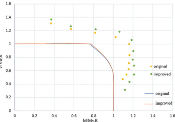
Resistance curves for shear and bending interaction were drawn according to EN 1993-1-3 specifications [12] for both original profile and improved cross section by intermediate stiffeners in theflanges. Moreover, numerical simulation for both sections was conducted by performing several finite element models. Indeed, the developed models were the same as the cantilever model which was carried out through the studying of shear case, but different cantilever lengths were implemented to define resistances for various bending and shear ratios. Imperfections for both shear and bending were introduced in order to investigate the beam behavior under shear and bending interaction. Figure 10 shows two continuous curves drawn according to Eurocode limitations.
Likewise, scattered points; obtained from numerical models, were plotted. In the figure, Vw,R and My,R are the design shear resistance of the web and the design moment
resistance of the cross-section respectively. As a result, the numerical outcomes were slightly higher than the theoretical ones.
6. CONCLUSIONS
To conclude this paper, several consequences could be predicted as follow:
1. Based on the comparison between the numerical simu- lation; verified by experimental data tests, and Eurocode, using higher local imperfection amplitude by 17%
approximately in EC might give better result in case of rectangular hollowflange sections.
2. Design rules to determine bending and bending and shear interaction capacities of RHFBs based on Eurocode tend to be somewhat conservative.
3. The improved section by using intermediate stiffeners in flanges in bending case increased the moment resistance of the original rectangular hollowflange profile by 4.4%.
4. In shear case, the results showed that current standard rules are not quite accurate to determine the design shear capacity of RHFBs, and that might be due that the design rules assume that only the web carries shear force while the examined profile gives extra support in shear case through itsflanges.
5. It can also be observed that the use of intermediate stiffener in the center of the web has no significant effect on shear resistance for the studied case.
At last, recommendations for future research works might be conducting more studies to develop the current design rules in Eurocode, and to determine the effect of different intermediate stiffener sizes and shapes for RHFBs.
REFERENCES
[1] H.-X. Wan and M. Mahendran,“Bending and torsion of hollow flange channel beams,”Eng. Struct., vol. 84, pp. 300–312, 2015.
[2] N. Tondini and A. Morbioli, “Cross-sectional flexur- alcapacityofcold-formedlaterally-restrained steel rectangular hol- lowflange beams,”Thin-Walled Struct., vol. 95, pp. 196–207, 2015.
[3] K. S. Wanniarachchia and M. Mahendran,“Experimental study of the section moment capacity of cold-formed and screw-fastened rectangular hollowflange beams,”Thin-Walled Struct., vol. 119, pp. 499–509, 2017.
[4] N. S. Trahair and J. J. Papangelis,“Lateral-distortional buckling of beams with hollowflanges and folded plate,”Eng. Struct., vol. 163, pp. 71–76, 2018.
[5] M. Karunakaran and M. H. Santhi,“Investigation on cold formed steel rectangular hollow flanged ‘z’beam section,”Int. J. Recent Res. Sci. Eng. Technol., vol. 2, no. 10, pp. 1–6, 2014.
[6] S. Jeyaragan and M. Mahendran,“Experimental investigation of the new built-up Litesteel beams,”in5th International Conference on Thin-walled Structures, Brisbane, Australia, Jun. 18–20, 2008, 2008, pp. 1–10.
Fig. 10.Shear force and bending moment interaction curves
flange beams with web stiffeners,” in Thirteenth International Specialty Conference on Cold-Formed Steel Structures, St. Louis, Missouri USA, Oct. 17–18, 1996, 1996, pp. 224–241.
[9] M. M. Joy and J. Mathew,“Analysis of rivet fastened rectangular hollowflange channel beams,”Int. Res. J. Eng. Technol., vol. 04, no. 4, pp. 3505–3510, 2017.
[10]ANSYS, Documentation for ANSYS-Release 19.2, Copyright SAS IP, Inc, 2018.
Sheeting, Bruxelles, CEN, 2006.
[13] EN 1993-1-5, Eurocode 3, Design of Steel Structures, Part 1–5:
Plated Structural Elements, Bruxelles, CEN, 2006.
[14] G. Brando, “Experimental tests on bracing type pure aluminum shear panels,”Pollack Period., vol. 2, no. 3, pp. 73–84, 2007.
[15] A. Formisano,“Experimental-numerical investigation on stiffened aluminum shear panels,”Pollack Period., vol. 1, no. 3, pp. 57–77, 2006.
Open Access. This is an open-access article distributed under the terms of the Creative Commons Attribution 4.0 International License (https://creativecommons.org/
licenses/by/4.0/), which permits unrestricted use, distribution, and reproduction in any medium, provided the original author and source are credited, a link to the CC License is provided, and changes–if any–are indicated. (SID_1)