PLASMA ARC HARDFACING OF BANDSAW BLADE TEETH
Bálint Palasik1, Enikő Bitay2, János Dobránszky3
1 BME Department of Materials Science and Engineering, Budapest, Hungary
2 Sapientia Hungarian University of Transylvania,
Faculty of Technical and Human Sciences, Târgu-Mureş–Corunca, Romania,
3 MTA–BME Research Group for Composite Science and Technology, Budapest, Hungary
Abstract
In this paper some developments of the plasma arc hardfacing of bandsawblade teeth were presented. After some preliminary experiments there were discovered imperfections, which may have caused the problems of the production. It was also determined, which di- mensions of a bandsawblade tooth should be measured in the following experiments. Fur- thermore, we defined, based on the standard EN ISO 15614-7 the work plan: which meas- urements should be carried out after the experiments. Moreover we successfully reduced the amount of the variables to be examined: only 8 factors of the originally founded 15 welding variables should have been examined according to regulations of the producer of the stellite tipping machine. After defining the imperfections, it was elaborated a Taguchi type design of experiments to gain deeper understanding of the process. Then we defined quality classes and determined what a tooth should have to get into one of them.
The experiments were performed on 128 welded bandsawblade’s teeth. We measured all the required dimensions with the image analyser software JMicroVision and graded all the teeth; the software IBM SPSS Statistics was applied for statistical surveys. On the base of these results, we determined the correlation between the tooth dimensions and welding parameters, by completing the analysis with the Minitab17 software’s DoE func- tion, mainly with ANOVA.
We carried out a control experiment series according to the Taguchi-method. As a re- sult, the amount of the welding consumable used was minimal, while the quality of the teeth did not deprave, resulting in a cost optimization. Also thanks to these experiments, it turned out that the process is very sensitive to any surface contaminations. They can cause porosity in the weld.
It was stated that the welding equipment was unstable in serial production of teeth with identical dimensions, even if they got the same classification. Therefore, as a conclusion of this development, we elaborated a controlling method of the variables and the cost reduc- tion of welding consumable.
Keywords: bandsaw blades, plasma arc welding, hardfacing, stellite, DOE
1.
IntroductionBandsaw blades are typically exposed to mechanical, and in many cases, thermal stresses, and therefore their surface must be designed so that they can withstand the effects they are exposed to, and the manufacturing process must not produce cracks or other material continuity defects. The teeth of the blade are exposed to very intense loads, and therefore they need additional reinforcement. This can be done by hardness-
enhancing heat treatment, i.e. hardening, or by surface treatment processes (e.g. plas- ma nitriding). In the bandsawblade industry, a more ductile material is build-up welded onto the saw blade teeth; this is called stelliting. This is a clear concept, but incorrect in general.
Stellite is the name of a Co-base alloy family, which can be attached to the base ma- terial and teeth of saw blades by various welding processes. Problems during the pro- cess have caused a lot of difficulties for workers in the area concerned, as it is a weld- ing technology with a lot of variables. Due to the number and type of imperfections make uneven the quality, we had to undertake a number of experiments and different material examinations to allow for proper regulation of production.
The aim of the research and development work was to reduce the additional post- machining time and tool wear due to the additional material affixed to the tooth head (Fig. 1) during stelliting and to enable a stable quality for the production of stellited teeth by using the available tools properly.
Figure 1 – Stellited tooth with a typical imperfection
The producer uses Vollmer GPA200 welding equipment which uses a transferred arc method for the welding process. The schema of this procedure is illustrated in Fig. 2.
Figure 2 – Schema of the plasma arc hardfacing of the tooth tip of a bandsaw blade [3]
Plasma torch
Mould Stellite
rod
Tooth
In the bandsawblade industry, usually Stellite 12 alloy is the preferred consumable.
This is a very versatile alloy between material types Stellite 6 and Stellite 1 in terms of to certain specifications (hardness, wear resistance).
It consists of a higher amount of hard carbides than Stellite 6, and has a higher re- sistance to corrosion and abrasive wear. Thanks to the higher tungsten content, it has much better properties at higher temperatures as well than the other two types; it is ex- cellently suitable even at around 700°C [1, 2].
There are no regulations in force regarding the base material for woodworking indus- try band saw blades. Generally speaking, a bandsaw blade must be hard, but also tough. Therefore, it is understandable that unalloyed eutectoide spring steel is most commonly used in domestic and European woodworking industry: namely C75 [3]. We used 100 mm wide saw blades having a 1.10 mm sheet thickness and tooth pitch NVN35 for the experiments.
2.
ExperimentalThe primary purpose of our work was to examine the quality stability of hardfacing plasma arc welding used for bandsaw blades; to investigate the issues occurred during the manufacturing, to perform examination of the various phenomena, to find possible methods for eliminating the causes and to reduce the cost of stellite consumption. For these purposes, we made the following steps:
2.1. Analysis of the manufacturing process
We found the following welding variables to be important during the observation of the manufacturing process:
preheating time, tp (s),
welding current, IW (A),
pilot arc current, IP (A),
stellite rod type, diameter, dSR (mm)
stellite rod rapid feed path (RP) (mm),
plasma torch path (BP) (mm),
stellite rod slow feed path (SP) (mm),
stellite rod feed rate (vSR) (mm/s),
plasma torch distance, LB (mm),
plasma torch angle (°),
stellite rod angle (°),
plasma gas flow rate (L/min),
shielding gas flow rate (L/min),
mould type,
mould angle (°),
cooling time (s),
plasma torch nozzle diameter, DB (mm),
tungsten electrode type,
tungsten electrode diameter, dE (mm),
tungsten electrode tip angle (°),
tungsten electrode blunting (mm),
tungsten electrode backset (mm).
2.2. Preliminary experiments
We performed preliminary experiments following the observation of the manufactur- ing process. The purpose of the preliminary experiments was to gather enough infor- mation about the procedure, to examine the alleged deviations that occur during the manufacturing process and to determine the most efficient method for the examinations based on the results of the sampling. During the preliminary experiments, we performed a factorial experiment through the examination of 4 welding variables. These variables were the following:
preheating time, tP (s),
welding current, IW (A),
plasma gas flow rate (L/min),
tungsten electrode blunting (mm).
In addition, we examined the impact of contaminants on the process.
2.3. Analysis of preliminary experiments
Several experiments and various material examinations had to be performed to ana- lyze the preliminary experiments. The ISO 15614-7 standard was used as the basis for the preparation of the examination plan. This applies to standardized examination methods, but since the manufacturing process is unique, and Standard 15614-7 is ap- plicable to the examination of overlay welding performed on standard sheet material, we found it necessary to extend and – as allowed by the standard – in some cases omit examinations.
The finished teeth first have to be visually inspected; this is also the method used during the manufacturing process (tooth edge retention, no undercuts or lack of materi- al, etc.). This was followed by the stereomicroscopic examination, during which we made photographs of the sides and the top of the teeth at appropriate magnification.
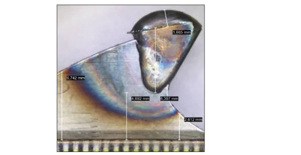
We later measured certain dimensions in these photographs with the JMicroVision software, which could characterize the process. The deviations of these values (Figure 3) can indicate the stability of the process with regard to the left and right side of the teeth and per tooth.
In addition, the standard requires the examination of the resulting surface with regard to cracks; this could be easily performed. However, we saw no reason to perform this test since this surface is grounded in the next step of the manufacturing process. There- fore, the cracks and surface deviations of the overlaid surface are of no consequence.
Figure 3 – Weld shape and HAZ geometry of a tooth created with preliminary experi- ment; the measures were performed by using JMicroVision image anaylser
In addition, the standard also requires the hardness examination of the specimens.
Considering the available hardness testing equipment, we found the Vickers micro- hardness test preferable for the side of the teeth because it does not cause too much permanent damage and allows several measurements to be performed on a relatively small surface.
In addition, Standard 15614-7 recommends performing ultrasonic examination in case of overlay welding to reveal possible material continuity deficiencies like porosity.
The ultrasonic examination is recommended by material examiners from a diameter of 6 mm; the blades are outside this range, and therefore we used X-ray microscopy exami- nation instead.
Once the examinations described above have been completed, polished samples can be taken from the examined teeth. The following examinations have to be carried out on polished samples:
hardness measurement,
macrostructural examination,
microstructural examination,
EDS-microanalysis by using scanning electron microscope.
Based on the obtained results and the observation of the manufacturing process, the experiments can be planned and, after performing them, evaluated.
3.
Findings and dissertation 3.1. Design of experiment (DoE)The DoE is an efficient method to optimize the number of experiments and evaluate the results. The majority of the cost in case of technical development work can be at- tributed to the experiments, and in addition to this, one would also have to consider the time required. Therefore, the experiment plans have to maximize the amount of obtain- able data for a given amount of experiments [4, 5].
We have chosen the Taguchi method based on these considerations.
Genichi Taguchi has improved the factorial experiment designing method. He re- duced the number of experiments necessary to reach optimum and increased the num-
ber of factors and interactions that can be easily examined. He experimented a lot and created some commonly used experiment plans based on his findings. He designed the orthogonal arrays system for the plans. In the orthogonal arrays, he managed to as- semble the most common factor combinations and defined how to appropriately place the major and less important effects and interactions in them [6, 7].
Steps to complete the Taguchi experiment:
1. The characteristics of the quality, the most important factors to be examined in the experiment and the possible values of their levels have to be defined in the conceptual stage;
2. Designing and conducting the experiment according to one of Taguchi methods;
3. Analysis of the results from which the optimal values have to be determined;
4. Conducting a control experiment under optimal conditions.
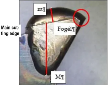
We created a classification system for qualifying the products; the system comprises 3 classes, and we have chosen the following properties to be used for assigning classes (Figure 4):
The M (the height of the stellite in the mould (mm)) dimension is 6.8 mm at mould 912416 in case of an uninclined mould. If this value reaches or exceeds 6.5 mm in the case of finished teeth, it means an aesthetic tooth shape indicating good quality and al- lowing for resharpening several times.
The m (the height of the stellite "cap" (mm)) dimension depends on a lot of things; it cannot be tied to existing physical boundaries like a mould. In truth, we want to keep it as minimal as possible, but under a certain value this jeopardizes the existence of the tooth edge. We found that if this value is below 1.6 mm when the saw tooth has attained the shape of mould, then the amount of the stellite overlay can be considered economi- cal.
Figure 4 – Main weld characteristics that must be measured during the evaluation of the experiments
We have chosen the third qualifying factor to be the presence of the tooth edge seen at the mould on a given tooth. No value can be assigned to this.
I. class-teeth that fulfil the 3 previous requirements assigned to this class.
II. class-teeth that do not fulfil 1 of the previous requirements assigned to this class.
III. class-teeth that do not fulfil more than 1 of the requirements of to this class.
At this point, we were already familiar with the welding variables (factors) to be exam- ined and their interactions. In addition, we have managed to determine the value range
Main cut- ting edge
of each factor (lower, upper level; Table 1) and to decide on the "values" of fixed varia- bles (Table 2). Based on the number of parameters and the number of the correlations between them, we considered the L16(215) Taguchi method to be the most suitable.
Many experiment sequences can be designed with this experiment plan, all depends on how many effects and how many interactions we want to examine during series of 16 experiments.
The relationship between factors and interactions was represented by Taguchi using a linear graph. The nodes of the graph are the factors, and the edges between the nodes are the correlations for the effects of the given node. The linear graph of this ex- periment is illustrated in Figure 5.
Figure 5 – Linear graph for examining 8 effects and 7 interactions [4]
1. welding current: I (A)
2. stellite rod feed angle, SRFA (mm) 3. undefined,
4. plasma torch tilt angle, PTTA (°) 5. plasma torch path: BP (mm)
6. correlation between the stellite rod feed angle and the plasma torch tilt angle 7. undefined
8. preheating time (s)
9. correlation between the preheating and the current 10. plasma gas flow rate, PGFR (L/min)
11. correlation between the plasma gas and the welding current
Table 1 – Level values of the main parameters examined during the experiment Factors Preheating
(s)
Ih
(A)
BP (mm)
SP (mm)
vSt
(mm/s)
Torch angle (°)
Stellite rod angle (°)
Plasma gas (L/min)
Level 1. 0.6 76 2.0 15.0 6.8 5 15 1.0
2. 1.0 80 3.0 15.5 7.3 7 17 1.1
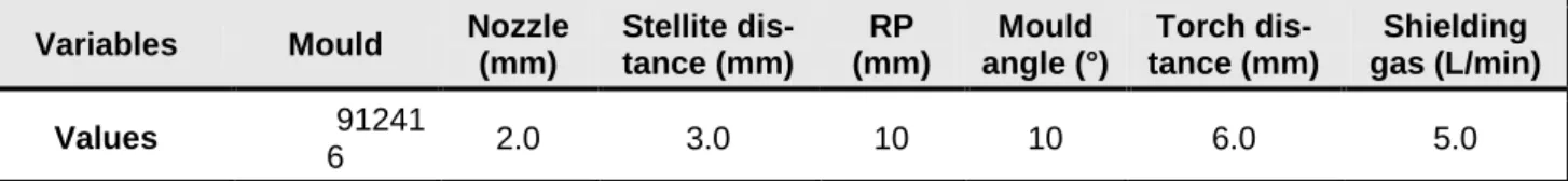
Table 2 – Fixed values used in the experiment
Variables Mould Nozzle (mm)
Stellite dis- tance (mm)
RP (mm)
Mould angle (°)
Torch dis- tance (mm)
Shielding gas (L/min)
Values 91241
6 2.0 3.0 10 10 6.0 5.0
12. stellite rod feed rate, SRFR: vSt (m/min)
13. correlation between the preheating and the current and vSt
14. stellite rod slow feed path: SP (mm) 15. undefined
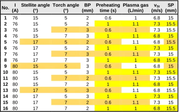
The experiment plan created in this way is illustrated in Table 3.
3.2. Evaluation of results
After the experiments were performed, we carried out the examination plan on the 128 teeth. The values measured by the JMicorVision software and the classification based on the images are indicated in Table 4 for experiment 14.
Porosity did not occur. No deviation could be observed on the polished samples. The texture met the expectations.
We examined the appropriateness of the settings with the trial version of IBM SPSS statistics. First, we examined the suitability the class definitions with different mathemat- ical methods (we examined the K-means cluster analysis with cross-table method, mid- dle clustering procedure with cross-table, discriminance analysis). In 82% of the cases, the software would have placed the saw teeth in the same way as our classification. Af- ter this, we examined the correlation between the dimensions measured on the saw teeth.
This revealed that there is correlation between almost all of the variables was ob- served, with the exception of HAZ (heat affected zone) and FogF (tooth surface). This means that choosing one from among the dependent variables to be observed may be enough when looking for the optimal experiment settings.
To this end, we examined the predictive ability of the different variables with the pro- gram and we found that the H value has the strongest indication for the "appropriate- ness" of the weld.
3.3. Search of the optimal variables
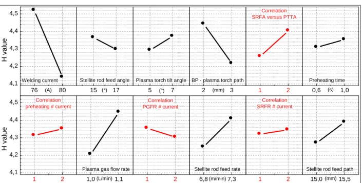
We loaded the data obtained into the trial version of the Minitab17 software and ana- lyzed the effect of the different welding factors and their correlations on H, and thus the process, by using the built-in Taguchi method, and examined the relevance of these ef- fects with S/N examination. This method provided an opportunity to find out which weld- ing variables are the "main" variables and in what proportions and direction should they be changed (Figure 6).
The lower and upper levels applied during the experiments are indicated at each fac- tor, while only 1 and 2 are indicated at the correlations. In addition, the scale on the left side of the figure contains the H values in mm. The longer the section is and the steeper the horizontal angle, the greater its impact is on the process.
We then analysed the cross effects and found them to be negligible. If we can fit a plane instead of a curve on a cross effect of two factors (3 points define a plane), then it is linear, and therefore, negligible. This is supported by our previous test of normality.
Consequently, the correlations do not have to be taken into consideration. This was fol- lowed by using the built-in optimization feature of the Minitab software.
Table 3 – The exact experiment plan of the main experiment sequence No. I
(A)
Stellite angle (°)
Torch angle (°)
BP (mm)
Preheating time (s)
Plasma gas (L/min)
vSt (m/s)
SP (mm)
1 76 15 5 2 0.6 1 6.8 15
2 76 15 5 2 1 1.1 7.3 15.5
3 76 15 7 3 0.6 1 7.3 15.5
4 76 15 7 3 1 1.1 6.8 15
5 76 17 5 2 0.6 1.1 6.8 15.5
6 76 17 5 2 1 1 7.3 15
7 76 17 7 3 0.6 1.1 7.3 15
8 76 17 7 3 1 1 6.8 15.5
9 80 15 5 3 0.6 1 6.8 15
10 80 15 5 3 1 1.1 7.3 15.5
11 80 15 7 2 0.6 1 7.3 15.5
12 80 15 7 2 1 1.1 6.8 15
13 80 17 5 3 0.6 1.1 6.8 15.5
14 80 17 5 3 1 1 7.3 15
15 80 17 7 2 0.6 1.1 7.3 15
16 80 17 7 2 1 1 6.8 15.5
Table 4 – Dimensions and evaluation of the saw teeth welded during experiment 14 of the experiment sequence.
Nr. H (mm) M (mm) m (mm) L (mm) Tooth top (mm2)
HHÖ (mm2)
14.1 3.665 6.788 1.172 6.603 17.743 49.943
14.2 3.734 6.759 1.28 6.841 17.876 47.028
14.3 4.601 5.892 1.745 7.082 19.024 49.525
14.4 3.645 6.709 1.304 6.698 18.114 48.616
14.5 4.059 6.493 1.324 6.728 18.158 60.372
14.6 4.177 6.453 1.814 7.237 19.75 69.288
14.7 3.724 6.749 1.595 6.892 18.203 64.944
14.8 3.704 6.709 1.296 6.659 17.924 69.769
Nr. FogF (mm2)
Quality Class
Mould filling (M > 6.5?)
Tooth tip edge present?
Cap uniform?
(m < 1.6)
14.1 36.164 1 Y Y Y
14.2 37.063 1 Y Y Y
14.3 35.001 2 N Y N
14.4 37.136 1 Y Y Y
14.5 36.355 2 N Y Y
14.6 35.299 2 N Y N
14.7 36.266 1 Y Y Y
14.8 37.209 1 Y Y Y
As a first step, we select an output parameter (H), then we specify to which value we want to optimize (minimum, maximum or custom set value). After that, the machine ex- amines the results achieved with the given factor levels and specifies – in accordance with the given conditions – the settings for the welding parameters to achieve the de- sired effect. The program gives a desirability value (D) for the search for the optimal range; this is an average value which is D = 0.9810 in this case. This means that with respect to the given output H values, the resulting values must be minimal with 98%
probability.
The 5 rows (H, H1, ..., H4) were examined separately by the program. The blue "y"
value is the H value in mm at the dashed line in the given row. The "d” value below the
"y" value is the desirability for each row. The values of the factors and their levels are shown in the upper part of the table, and the “current” value is indicated in red. This cur- rent value is the response given to the optimization. Each parameter has a separate window in the different rows. In these windows, a black dot marks one or the other fac- tor level. The program considered a black dot appropriate if it was located on the dashed line, and the more such dots coincide with the red line (which again refers to the optimal values) the greater the probability that it is the value wanted. This diagram also shows the direction the H mean values were shifted in during the experiments by the lower and upper levels of the individual factors. Based on the results obtained, the opti- mized welding variables for the control examination were as follows:
Stellite rod: distance = 3 mm; SP = 15 mm; vSt = 6.8 m/s; SRTA = 17°, RP = 11 mm;
Plasma torch: distance = 6 mm; BP = 3 mm PTTA = 5°;
Gas flow rate: shielding = 5.0 L/min; plasma = 1.0 L/min.
Current = 80 A.
Preheating = 1.0 s.
3.4. Control experiment and evaluation
The control experiment had to be carried out twice because the saw blade used for the first instance became contaminated, and the rust and silicon carbide powder depos- ited to the tooth head caused sparking during the welding. It was later revealed that the
15 (°) 17 Stellite rod feed angle
5 (°) 7 Plasma torch tilt angle
2 (mm) 3 BP - plasma torch path
1 2
Correlation SRFA versus PTTA
0,6 (s) 1,0 Preheating time
1 2
4,1 4,2 4,3 4,4
4,5 Correlation preheating # current
H value
1,0(L/min)1,1 Plasma gas flow rate
1 2
Correlation PGFR # current
6,8(m/min)7,3 Stellite rod feed rate
1 2
Correlation SRFR # current
15,0(mm)15,5 Stellite rod feed path
76 80
4,1 4,2 4,3 4,4 4,5
(A) Welding current
H value
Figure 6 – Influence of the factors and correlations of the experiment
teeth at which this phenomenon occurred became porous. The second time, however, the experiment succeeded and gave the expected result.
4.
ConclusionsWe made the following suggestions based on the findings of the examinations:
During the welding process of the saw teeth, a 0.1–0.3 mm increment should be used for setting the filler material to obtain more accurate results.
When decreasing the SP value, it is recommended to increase the feed rate of the stellite minimally. During plasma welding, some of the material is lost due to the under- cut, so if the amount of the filler material is reduced, but heat input is not and the feed rate is not increased, a greater percentage of the material can be lost to undercut. This may be true in the reversed scenario as well. If more filler material is to be overlaid onto the surface, it is advisable to decrease the stellite feed rate a bit because this gives more time for the greater amount of material to melt [8].
If the operator wants the weld deposit to flow deeper in the mould in case of a 2 mm plasma nozzle, it is advisable to change the electric current first instead of the plasma gas. Based on what we experienced during the experiment, decreasing the plasma gas by 0.1 L/min had roughly the same effect as increasing the current by 4 A.
It is recommended to install a camera system that allows workers to see the area of the torch and the mould at a higher magnification. This would make it easier to fine-tune the various welding variables (stellite distance, stellite position, stellite rod angle, ...).
Cleaning the parts is essential to avoid hardfacing defects and to achieve good quali- ty. It is recommended to inspect and replace as necessary all components that may be contaminated at least at the end of the shifts (it would be optimal every 4 hours).
Not only the component’s cleanliness requires attention! Contaminants can introduce surface corrosion in case of C75 steels, and therefore the workers should wear clean gloves. Plasma arc welding has proven to be very sensitive to surface contamination.
Therefore, the bandsawblade’s teeth should not be touched after pregrinding as it may lead to formation of porosity.
5.
AcknowledgmentsWe would like to thank the staff of A-Lap Ltd. for making the successful completion of my thesis possible. We would also like to thank Professor Enikő Réka Fábián for advice and help in conducting the metallographic examinations.
Furthermore, we would like to thank Professor László Ketskeméty for his help in mathematical statistics and Professor Klára Wenzel whose Taguchi method based ex- periment designing notes are unique in the entire BME and in Hungary.
Special thanks to Mr. János Balázs for his help in measuring technics.
Between the authors Enikő Bitay was supported by the MTA Domus Hungarica Grant Program: 5242/4/2017/HTMT.
References
[1] Hardfacing Alloys. Kennametal, 2016.
[2] Ferozhkhana MM, Duraiselvamb M, Kumarc KG, Ravibharathd R: Plasma trans- ferred arc welding of Stellite 6 alloy on stainless steel for wear resistance. Procedia Technology 25, 2016, 1305–1311.
[3] Dobránszky J: Thesis on the failure of woodcutting bandsaw blades. Budapest 2014.
(in Hungarian)
[4] Vincze I: Maethematical statistics with industrial applications. Műszaki Könyvkiadó, Budapest, 1968. (in Hungarian)
[5] Kemény S, Deák A: Designn and analysis of experiments. Műszaki Könyvkiadó, Bu- dapest, 2003. (in Hungarian)
[6] Márkus L: Statistical methods of industrial design of experiment. ELTE TTK, 2011.
(in Hungarian)
[7] Wenzel K: Design of experiments with Taguchi-method. BME MOGI, 2013. (in Hun- garian)
[8] Keränen M: Effect of welding parameters of plasma transferred arc welding method on abrasive wear resistance of 12V tool steel deposit. Doctoral Dissertation, Aalto University, 2010.
![Figure 2 – Schema of the plasma arc hardfacing of the tooth tip of a bandsaw blade [3]](https://thumb-eu.123doks.com/thumbv2/9dokorg/1416607.119686/2.892.212.621.775.1060/figure-schema-plasma-arc-hardfacing-tooth-bandsaw-blade.webp)