ceramics
Article
Influence of Graphene and Graphene Oxide on Properties of Spark Plasma Sintered Si 3 N 4 Ceramic Matrix
Katalin Balazsi1, Mónika Furkó1, Piotr Klimczyk2 and Csaba Balázsi1,*
1 Institute for Technical Physics and Materials Science, Centre for Energy Research, Konkoly-Thege N. str.
29−33, 1121 Budapest, Hungary; balazsi.katalin@energia.mta.hu (K.B.); furko.monika@energia.mta.hu (M.F.)
2 Research Network Łukasiewicz, The Institute of Advanced Manufacturing Technology, Wroclawska 37A, 30−011 Krakow, Poland; piotr.klimczyk@ios.krakow.pl
* Correspondence: balazsi.csaba@energia.mta.hu
Received: 6 January 2020; Accepted: 2 February 2020; Published: 5 February 2020
Abstract:The sintering of ceramic matrix composites is usually carried out by raising the sintering temperature below the melting point of components. Spark plasma sintering (SPS) has the capability to densify ceramics at a relatively low temperature in a very short time. Two different additions, multilayered graphene (MLG) and graphene oxide (GrO), were added to Si3N4ceramic matrix in various amount; 5 wt% and 30 wt%. The influence of reinforcing phase on final properties of spark plasma sintered Si3N4composite was studied. The uniaxial-pressure-assisted SPS sintering resulted in a preferential alignment of both type of graphene in the Si3N4ceramic matrix, leading to highly anisotropic properties with lower mechanical behavior but better tribological and electrical properties.
Keywords: multilayered graphene; graphene oxide; SPS; Si3N4; ceramic composite
1. Introduction
Silicon nitride (Si3N4) has been used over the past decade as an insulating material with extreme high hardness, strength and toughness in a wide range of temperatures. [1], and is one of the most promising candidates as structural ceramic, as well. It also has many other advantageous properties such as good thermal conductivity, tribological and wear properties [1,2]. To improve functional and mechanical properties of the monolithic ceramics, the addition of reinforcing phase has been used. Nowadays, different carbon allotrops like single-wall carbon nanotube [3], multi-wall carbon nanotubes [4], graphene [5,6], reduced graphene oxide powders (rGO) [7] or carbon black [8] are applied to enhance various properties of ceramics. Generally, graphene is one atomic thick, two-dimensional layer and usually exists as a film. Nevertheless, the gradually growing interest in graphene production has led to the creation of various graphene forms that can be used for unique purposes. Graphene has also many unique and outstanding properties; therefore, it is also a very promising candidate as nanofiller material in various applications. The intrinsic mechanical properties of graphene make it one of the strongest materials available [9–11]. Graphene is considered to have excellent electrical properties [12–14] and high thermal resistance [15–17] as well as a high surface area (highest adsorption and surface reactions), electron mobility, thermal conductivity and mechanical strength [18]. GrO can also be used as nanofiller since it has similar properties to graphene and has become more commonly available recently. The GrO contains heteroatomic irregularity and structural defects compared to the pure form of graphene. In addition, GO can also be used as a dielectric material for the purpose of energy storage [19]. Recently, a very interesting point raised by a new ceramic/graphene design is that graphene is not used as a conventional ‘reinforcement’ but rather to engineer a fine network of relatively weak interfaces that provide electrical conductivity and fracture resistance [20]. The most common methods for processing ceramic composites are mechanical alloying, powder processing
Ceramics2020,3, 40–50; doi:10.3390/ceramics3010005 www.mdpi.com/journal/ceramics
Ceramics2020,3 41
methods followed by different sintering techniques [21]. There are only a few data regarding the investigation of the effect of graphene and graphene oxide reinforcing to silicon nitride base ceramics focusing on their tribological, electrical and mechanical performance. One of these works is Llorente et al. [22]. They prepared spark plasma sintered Si3N4with large 20 vol % graphene nanoplateles and exhibited better tribological response than Si3N4and measured the 50% reduction in the friction [22].
From the point of application view, Si3N4ceramics can be used as ball components of bearing systems under lubricated conditions. The sliding contact of self-mated Si3N4–Si3N4 tribopairs under dry conditions produces a high friction coefficient and high wear rate because the abrasive wear is affected by the intrinsic brittle nature of ceramics [23,24].
In this work, the multilayered graphene (MLG) prepared by highly efficient attritor milling and graphene oxide (GrO) synthetized from MLG were used as reinforcing phases. The influence of MLG and GrO on properties of spark plasma sintered Si3N4composites was studied.
2. Experimental Part
2.1. Preparation of Multilayered Graphene
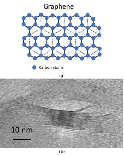
Generally, graphene is one atomic, thick, two-dimensional layer and usually exists as a film (Figure1a). Nevertheless, the gradually growing interest in graphene production has led to the creation of various graphene forms that can be used for unique purposes. The synthetic graphite powder (Sigma Aldrich,<20 m) was used as base material. The graphite was milled in the highly efficient attritor mill (Union Process, type 01-HD/HDDM) equipped with zirconia discs and grinding media with diameter 1 mm. The milling was run with rotation speed of 3000 rpm for 10 h in ethanol [25].
This process resulted in a multilayered graphene (Figure1b).
Ceramics 2020, 3 FOR PEER REVIEW 2
a new ceramic/graphene design is that graphene is not used as a conventional ‘reinforcement’ but rather to engineer a fine network of relatively weak interfaces that provide electrical conductivity and fracture resistance [20]. The most common methods for processing ceramic composites are mechanical alloying, powder processing methods followed by different sintering techniques [21].
There are only a few data regarding the investigation of the effect of graphene and graphene oxide reinforcing to silicon nitride base ceramics focusing on their tribological, electrical and mechanical performance. One of these works is Llorente et al. [22]. They prepared spark plasma sintered Si3N4
with large 20 vol % graphene nanoplateles and exhibited better tribological response than Si3N4 and measured the 50% reduction in the friction [22]. From the point of application view, Si3N4 ceramics can be used as ball components of bearing systems under lubricated conditions. The sliding contact of self-mated Si3N4–Si3N4 tribopairs under dry conditions produces a high friction coefficient and high wear rate because the abrasive wear is affected by the intrinsic brittle nature of ceramics [23,24].
In this work, the multilayered graphene (MLG) prepared by highly efficient attritor milling and graphene oxide (GrO) synthetized from MLG were used as reinforcing phases. The influence of MLG and GrO on properties of spark plasma sintered Si3N4 composites was studied.
2. Experimental Part
2.1. Preparation of Multilayered Graphene
Generally, graphene is one atomic, thick, two-dimensional layer and usually exists as a film (Figure 1a). Nevertheless, the gradually growing interest in graphene production has led to the creation of various graphene forms that can be used for unique purposes. The synthetic graphite powder (Sigma Aldrich, <20 m) was used as base material. The graphite was milled in the highly efficient attritor mill (Union Process, type 01-HD/HDDM) equipped with zirconia discs and grinding media with diameter 1 mm. The milling was run with rotation speed of 3000 rpm for 10 h in ethanol [25]. This process resulted in a multilayered graphene (Figure 1b).
(a)
(b)
Figure 1.Structure of multilayered graphene. (a) Schematic view, (b) TEM image.
Ceramics2020,3 42
The average thickness of graphene multilayers was 13.76 nm (Figure1b) according to TEM investigations. These results imply that the graphene multilayers were composed of approximately 40 graphene layers on average.
2.2. Preparation of Graphene Oxide
The previously prepared MLGs were treated in three steps. Firstly, the powders were dispersed in cc.HNO3solution and stirred at 80◦C for 4 h. After that, 50% H2O2was added to the dispersion under continuous stirring and kept at room temperature for 16 h. The dispersion was then filtered using filter paper grade 3, the filtrate washed with 30% H2O2and 96% ethanol and dried at 150◦C in air. In the second step, the dried powders were collected and put in oven (Denkal 4K/1100) and heat treated at 850◦C for thermal oxidation (Figure2a,b). Finally, a portion of treated powders were dispersed again in 96% ethanol and sonicated in ultrasonic bath (Elmasonic E60H) for 3 h at 70◦C to examine the effect of ultrasound on the exfoliation rate of graphene oxide multilayers, then the solvent was evaporated at 80◦C [26].
Ceramics 2020, 3 FOR PEER REVIEW 3
Figure 1. Structure of multilayered graphene. (a) Schematic view, (b) TEM image.
The average thickness of graphene multilayers was 13.76 nm (Figure 1b) according to TEM investigations. These results imply that the graphene multilayers were composed of approximately 40 graphene layers on average.
2.2. Preparation of Graphene Oxide
The previously prepared MLGs were treated in three steps. Firstly, the powders were dispersed in cc.HNO3 solution and stirred at 80 °C for 4 h. After that, 50% H2O2 was added to the dispersion under continuous stirring and kept at room temperature for 16 h. The dispersion was then filtered using filter paper grade 3, the filtrate washed with 30% H2O2 and 96% ethanol and dried at 150 °C in air. In the second step, the dried powders were collected and put in oven (Denkal 4K/1100) and heat treated at 850 °C for thermal oxidation (Figure 2a,b). Finally, a portion of treated powders were dispersed again in 96% ethanol and sonicated in ultrasonic bath (Elmasonic E60H) for 3 h at 70 °C to examine the effect of ultrasound on the exfoliation rate of graphene oxide multilayers, then the solvent was evaporated at 80 °C [26].
(a) (b)
Figure 2. Structure of graphene oxide. (a) Schematic view, (b) TEM image.
2.3. Preparation of Composites
A commercial silicon nitride powder (α-Si3N4, UBE Corp.) with 0.6 µm average particle size, 4.8 m2/g specific surface area was used as matrix material. The powder mixture of 90 wt% Si3N4 (Ube, SN-ESP), 4 wt% Al2O3 (Alcoa, A16 average particle size 400 nm) and 6 wt% Y2O3 (H.C. Starck, grade C, average particle size 700 nm) was milled by the highly efficient attritor mill (Union Process, type 01-HD/HDDM) using zirconia agitator discs and grinding media with diameter ~1 mm in 750 cm3 zirconia tank. The milling process was performed at the high rotation speed of 3000 min−1 for 5 h in ethanol. In both cases, reinforcing phase was added in the last 0.5 h of milling process in 5 wt% and 30 wt%. The milled powder mixtures were sintered by spark plasma sintering (SPS, (FCT system, Germany) in vacuum at 1600 °C, 50 MPa-mechanical pressure, 10 min dwelling time, 30 mm diameter sized discs. The applied heating rate was 100 °C/min.
2.4. Characterization Methods
The fracture surfaces of the layers were further studied by scanning electron microscopy (SEM/FIB Carl Zeiss 1540XB) at 5 kV acceleration voltage with Everhart-Thornley and InLens secondary electron detectors. A Röntec Si(Li) detector and the Bruker Esprit 1.9 software were applied for EDX elemental analysis (acceleration voltage 8 kV). Phase analysis was determined based on X- ray diffractograms recorded at room temperature using a Bruker AXS D8X-ray micro-diffractometer (XRD operating at 40 kV and 40 mA, Cu Kα radiation, 0.15418 nm), equipped with a focusing Göbel
Figure 2.Structure of graphene oxide. (a) Schematic view, (b) TEM image.
2.3. Preparation of Composites
A commercial silicon nitride powder (α-Si3N4, UBE Corp.) with 0.6µm average particle size, 4.8 m2/g specific surface area was used as matrix material. The powder mixture of 90 wt% Si3N4
(Ube, SN-ESP), 4 wt% Al2O3(Alcoa, A16 average particle size 400 nm) and 6 wt% Y2O3(H.C. Starck, grade C, average particle size 700 nm) was milled by the highly efficient attritor mill (Union Process, type 01-HD/HDDM) using zirconia agitator discs and grinding media with diameter ~1 mm in 750 cm3 zirconia tank. The milling process was performed at the high rotation speed of 3000 min−1for 5 h in ethanol. In both cases, reinforcing phase was added in the last 0.5 h of milling process in 5 wt% and 30 wt%. The milled powder mixtures were sintered by spark plasma sintering (SPS, (FCT system, Germany) in vacuum at 1600◦C, 50 MPa-mechanical pressure, 10 min dwelling time, 30 mm diameter sized discs. The applied heating rate was 100◦C/min.
2.4. Characterization Methods
The fracture surfaces of the layers were further studied by scanning electron microscopy (SEM/FIB Carl Zeiss 1540XB) at 5 kV acceleration voltage with Everhart-Thornley and InLens secondary electron detectors. A Röntec Si(Li) detector and the Bruker Esprit 1.9 software were applied for EDX elemental analysis (acceleration voltage 8 kV). Phase analysis was determined based on X-ray diffractograms recorded at room temperature using a Bruker AXS D8X-ray micro-diffractometer (XRD operating at 40 kV and 40 mA, Cu Kαradiation, 0.15418 nm), equipped with a focusing Göbel mirror and a GADDS 2D detector. Diffraction patterns were collected for a 2θrange from 20◦to 90◦with 1◦/min steps using flat plane geometry. The relative number of phases in the composites was calculated using
Ceramics2020,3 43
the Diffrac.Eva software (Bruker). The structural investigation was performed by transmission electron microscopy (TEM, Philips CM-20 with accelerating voltage 200 kV). The hardness was tested by Vickers indentation (hardness testers LECO 700AT) with 19.61 N load for ceramic composites containing 0% and 5% MLG or GrO, while 4.903 N for samples containing 30% MLG or GrO particles and the indentation fracture toughness was determined based on the Niihara equation [27]. The density of all sintered composites was measured applying the Archimedes method. Vickers hardness (testers LECO 700AT) with 19.61 N load for ceramic composites containing 0% and 5 wt% reinforcing phase, while 4.903 N for samples containing 30 wt% reinforcing phase. The 3-point bending strength values were determined by bending tests (tensile/loading machine INSTRON-1112). The Young’s moduli were determined by Panametric instrument (Epoh III model 2300) using ultrasonic wave transition method.
The friction coefficient was measured by tribometer (DTHT 70010, CSM Instrument, Switzerland) on pin-on-disk mode by 5 mm diameter Si3N4balls. The specimens were tested with an applied load of 2 N, at air atmosphere, at room temperature with a relative humidity of 60±15%. The total sliding distance was 100 m and the sliding velocity was 0.06 m/s. The electrical conductivity of samples was measured by two-point DC resistance measurements using Voltcraft VC140 type multimeter.
3. Results and Discussion
3.1. Mechanical Properties of Spark Plasma Sintered Si3N4-Based Composites
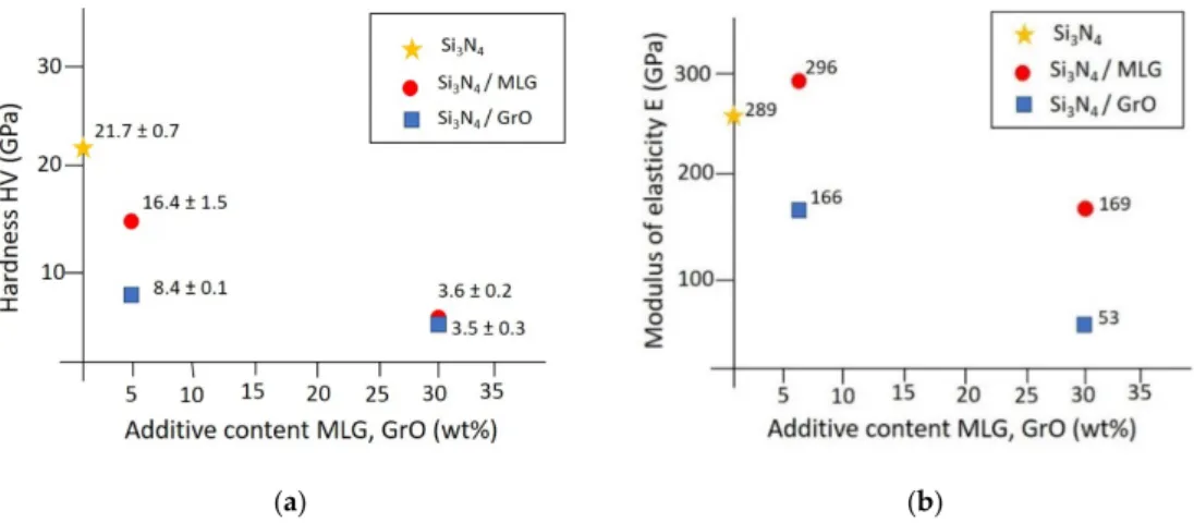
The determination of the hardness and modulus of elasticity allow useful qualitative conclusions regarding the mechanical properties of ceramic composite materials. Typically, the introduction of carbon reinforcing phases into ceramics leads to lower hardness, and its effect on the fracture toughness is ambiguous, even though there are some toughening mechanisms present in the crack, such as crack deflection, crack bridging and fibers pullout [28,29]. The hardness of different carbon phase added Si3N4ceramic matrix composites showed values between 11 and 19 GPa [4,30,31] depending on the sintering method and amount of reinforcing phase. A value of about 22 GPa was measured for spark plasma sintered Si3N4reference (Figure3a). As expected, 5 wt% and 30 wt% of MLG and GrO carbon reinforcing phases had a negative influence on the hardness of the final composites (Figure3a).
In the case of 5 wt% addition, higher hardness was observed than for 30 wt%. According to these results, the Si3N4-based composite with 5 wt% MLG content showed two times higher hardness and modulus of elasticity than the composite with 5 wt% GrO. However, in the case of 30 wt% MLG and GrO content, composites gave the same values (Figure3). Furthermore, modulus of elasticity (E) of ceramics depends on porosity content [32]. This fact is unanimously equal to results of Si3N4-based composites (Figure3b), namely, in both types of graphene, the higher amount decreased this value.
However, the MLG addition resulted in higher modulus values than in the GrO case indifferent of carbon amount in the ceramic matrix (Figure3b).
Ceramics 2020, 3 FOR PEER REVIEW 5
(a) (b)
Figure 3. Mechanical properties of Si3N4-based composites. (a) hardness, (b) modulus of elasticity.
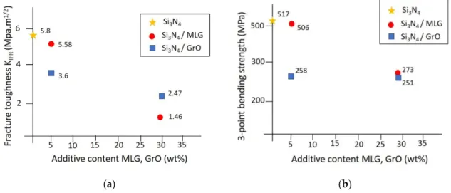
One of the most important parameters of composites is the fracture toughness, which describes the ability of a material containing a crack to resist fracture. The graphene plays a favorable role by bridging the cracks healing the crack openings as it is proved by the crack morphology. The fracture toughness of the composites decreased with the increase of the carbon phase content, and the maximum value was reached for 5 wt% MLG content (Figure 4a). The decrease in toughness is believed to be associated with the weak interface connections between the graphene and the matrix.
A similar tendency has been found for the 3-point bendig strength of composites (Figure 4b).
Monolitic Si3N4 showed the higher value ~ 517 MPa. The 5 wt% MLG addition resulted in similar strength value.
(a) (b)
Figure 4. Fracture behavior of Si3N4-based composites. (a) fracture toughness, (b) 3-point bending strength. KIFR = 0.0334(E/H)0.4(P/l1.5), where H is the Vickers hardness, E is the modulus of elasticity, P is the applied force and l is the length of cracks.
On the other hand, GrO addition due to different structure had more negative effect on strength and toughness of composites for both contents (Figure 4b). According to the results above, it could be seen that the more porous layer with higher graphene content under a tensile stress was, the main factor for fracture during the three-point bending test.
3.2. Structural Properties of Spark Plasma Sintered Si3N4-Based Composites
The density values were the lowest for the reference Si3N4 ceramic, while the highest values were obtained in the cases of 5% MLG and GO reinforcing phases (Figure 5). The density values decreased with increasing carbon phase content, approaching the value of reference ceramic. The lower density Figure 3.Mechanical properties of Si3N4-based composites. (a) hardness, (b) modulus of elasticity.
Ceramics2020,3 44
One of the most important parameters of composites is the fracture toughness, which describes the ability of a material containing a crack to resist fracture. The graphene plays a favorable role by bridging the cracks healing the crack openings as it is proved by the crack morphology. The fracture toughness of the composites decreased with the increase of the carbon phase content, and the maximum value was reached for 5 wt% MLG content (Figure4a). The decrease in toughness is believed to be associated with the weak interface connections between the graphene and the matrix. A similar tendency has been found for the 3-point bendig strength of composites (Figure4b). Monolitic Si3N4
showed the higher value ~ 517 MPa. The 5 wt% MLG addition resulted in similar strength value.
Ceramics 2020, 3 FOR PEER REVIEW 5
(a) (b)
Figure 3. Mechanical properties of Si3N4-based composites. (a) hardness, (b) modulus of elasticity.
One of the most important parameters of composites is the fracture toughness, which describes the ability of a material containing a crack to resist fracture. The graphene plays a favorable role by bridging the cracks healing the crack openings as it is proved by the crack morphology. The fracture toughness of the composites decreased with the increase of the carbon phase content, and the maximum value was reached for 5 wt% MLG content (Figure 4a). The decrease in toughness is believed to be associated with the weak interface connections between the graphene and the matrix.
A similar tendency has been found for the 3-point bendig strength of composites (Figure 4b).
Monolitic Si3N4 showed the higher value ~ 517 MPa. The 5 wt% MLG addition resulted in similar strength value.
(a) (b)
Figure 4. Fracture behavior of Si3N4-based composites. (a) fracture toughness, (b) 3-point bending strength. KIFR = 0.0334(E/H)0.4(P/l1.5), where H is the Vickers hardness, E is the modulus of elasticity, P is the applied force and l is the length of cracks.
On the other hand, GrO addition due to different structure had more negative effect on strength and toughness of composites for both contents (Figure 4b). According to the results above, it could be seen that the more porous layer with higher graphene content under a tensile stress was, the main factor for fracture during the three-point bending test.
3.2. Structural Properties of Spark Plasma Sintered Si3N4-Based Composites
The density values were the lowest for the reference Si3N4 ceramic, while the highest values were obtained in the cases of 5% MLG and GO reinforcing phases (Figure 5). The density values decreased with increasing carbon phase content, approaching the value of reference ceramic. The lower density
Figure 4. Fracture behavior of Si3N4-based composites. (a) fracture toughness, (b) 3-point bending strength. KIFR=0.0334(E/H)0.4(P/l1.5), where H is the Vickers hardness, E is the modulus of elasticity, P is the applied force and l is the length of cracks.
On the other hand, GrO addition due to different structure had more negative effect on strength and toughness of composites for both contents (Figure4b). According to the results above, it could be seen that the more porous layer with higher graphene content under a tensile stress was, the main factor for fracture during the three-point bending test.
3.2. Structural Properties of Spark Plasma Sintered Si3N4-Based Composites
The density values were the lowest for the reference Si3N4ceramic, while the highest values were obtained in the cases of 5% MLG and GO reinforcing phases (Figure5). The density values decreased with increasing carbon phase content, approaching the value of reference ceramic. The lower density can be explained by the porous microstructure of the samples induced by MLG and GrO particles, whereas low sintering temperature (1600◦C) and short sintering time (10 min) are responsible for lower density of reference Si3N4ceramic. In other research work [33], the authors described that the graphene platelets induced porosity in the matrix and reduced the size of the Si3N4 grains in the resulting composites. The similar effect was observed for spark plasma sintered composites (Figures6and7).
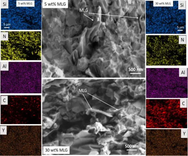
α-Si3N4has an equiaxial structure. In contrast,β- Si3N4is elongated, needle-shaped and less hard thanα- Si3N4. Due to its rod-like shape, the material may have an inhibitory effect on crack propagation, and thus, the material containingβ- Si3N4has a higher toughness than the material containing onlyα- Si3N4. The structural observations of MLG and GrO added composites are shown in Figures6and7. A very similar structure with Si3N4grains with average size of 500 nm, and MLG or GrO dispersed in matrix and embedded into ceramic grains was found. The higher amount of MLG increased the porosity of sintered composite. The elemental analysis confirmed the homogeneity of material and high dispersion of graphene addition. The Y and Al map referred the location of sintering
Ceramics2020,3 45
additives (Al2O3, Y2O3) between ceramic grains. Al shows segregation at some extent in the case of GrO additions (Figure7).
Ceramics 2020, 3 FOR PEER REVIEW 6
can be explained by the porous microstructure of the samples induced by MLG and GrO particles, whereas low sintering temperature (1600 °C) and short sintering time (10 min) are responsible for lower density of reference Si3N4 ceramic. In other research work [33], the authors described that the graphene platelets induced porosity in the matrix and reduced the size of the Si3N4 grains in the resulting composites. The similar effect was observed for spark plasma sintered composites (Figures 6 and 7).
α -Si3N4 has an equiaxial structure. In contrast, β- Si3N4 is elongated, needle-shaped and less hard than α- Si3N4. Due to its rod-like shape, the material may have an inhibitory effect on crack propagation, and thus, the material containing β- Si3N4 has a higher toughness than the material containing only α- Si3N4. The structural observations of MLG and GrO added composites are shown in Figures 6 and 7. A very similar structure with Si3N4 grains with average size of 500 nm, and MLG or GrO dispersed in matrix and embedded into ceramic grains was found. The higher amount of MLG increased the porosity of sintered composite. The elemental analysis confirmed the homogeneity of material and high dispersion of graphene addition. The Y and Al map referred the location of sintering additives (Al2O3, Y2O3) between ceramic grains. Al shows segregation at some extent in the case of GrO additions (Figure 7).
Figure 5. Measured density of Si3N4-based composites.
Figure 5.Measured density of Si3N4-based composites.
Ceramics 2020, 3 FOR PEER REVIEW 7
Figure 6. Structural observations of multilayered graphene (MLG) added Si3N4 composites with elemental maps of Si, N, Al, C and Y elements.
The GrO additions located between ceramic particles hinder the generation and growth of interparticle contacts (Figure 7). These structural observations confirmed that the carbon reinforcing phase has been located in porosities between grains of Si3N4 ceramic matrix.
Figure 6. Structural observations of multilayered graphene (MLG) added Si3N4 composites with elemental maps of Si, N, Al, C and Y elements.
Ceramics2020,3 46
The GrO additions located between ceramic particles hinder the generation and growth of interparticle contacts (Figure7). These structural observations confirmed that the carbon reinforcing phase has been located in porosities between grains of Si3N4ceramic matrix.
Ceramics 2020, 3 FOR PEER REVIEW 8
Figure 7. Structural observations of GrO added Si3N4 composites with elemental maps of Si, N, Al, C and Y elements.
The higher GrO blocked the growing of Si3N4grains (Figure 7), increased the porosity and decreased the density (Figure 5) of sintered composite. The elemental map investigation confirmed that it has successfully created a homogenous dispersion of the second phase (graphene) in ceramic composites for 5 and 30 wt% GrO as well.
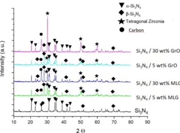
In the case of reference material, mainly α-Si3N4 phase (JCPDS 01-076-1407) can be observed with main characteristic peaks at 2Θ = 22.921, 26.514 and 31.820 and a small amount of β-Si3N4 (JCPDS 01- 082-0695) (Figure 8) due to short sintering time. The calculated phase ratio of α:β phase of Si3N4 was 88:5 wt%. In all composites, the distinguishing characteristic peaks for tetragonal zirconia appear at 2θ = 30.2, 34.5, 50.2 and 60.2 corresponding to the (101), (110), (200) and (211) reflections (JCPDS 70- 1769) which indicated contribution from ZrO2 grinding media resulting from high efficient attrition milling.
Figure 7.Structural observations of GrO added Si3N4composites with elemental maps of Si, N, Al, C and Y elements.
The higher GrO blocked the growing of Si3N4 grains (Figure7), increased the porosity and decreased the density (Figure5) of sintered composite. The elemental map investigation confirmed that it has successfully created a homogenous dispersion of the second phase (graphene) in ceramic composites for 5 and 30 wt% GrO as well.
In the case of reference material, mainlyα-Si3N4phase (JCPDS 01-076-1407) can be observed with main characteristic peaks at 2Θ= 22.921, 26.514 and 31.820 and a small amount ofβ-Si3N4 (JCPDS 01-082-0695) (Figure8) due to short sintering time. The calculated phase ratio ofα:βphase of Si3N4was 88:5 wt%. In all composites, the distinguishing characteristic peaks for tetragonal zirconia appear at 2θ=30.2, 34.5, 50.2 and 60.2 corresponding to the (101), (110), (200) and (211) reflections (JCPDS 70-1769) which indicated contribution from ZrO2grinding media resulting from high efficient attrition milling.
A key factor of a stable processing technology is the preventing of degradation of graphene during sintering process. In all composites, the presence ofα-Si3N4as main phase,β-Si3N4minor phase and carbon phase after sintering is proved (Figure8, carbon peak (002), (JCPDS 89–7213)). Sintering oxide additives are in amorphous phase in grain boundaries, and they are not shown in XRD diagram.
Ceramics2020,3 47
Ceramics 2020, 3 FOR PEER REVIEW 9
Figure 8. XRD analysis of Si3N4-based composites.
A key factor of a stable processing technology is the preventing of degradation of graphene during sintering process. In all composites, the presence of α -Si3N4 as main phase, β -Si3N4 minor phase and carbon phase after sintering is proved (Figure 8, carbon peak (002), (JCPDS 89–7213)).
Sintering oxide additives are in amorphous phase in grain boundaries, and they are not shown in XRD diagram.
3.3. Tribological and Electrical Properties of Spark Plasma Sintered Si3N4-Based Composites
The carbon phase content caused considerable decrease of the friction coefficient (Figure 9), which was around 0.8 for reference Si3N4. In the cases of both MLG and GrO added composites, these values have been reduced by more than half. The friction coefficient (COF) for 5 wt% MLG and GrO containing composites changed between 0.35 and 0.4, while for composites with 30 wt% MLG and GrO content had almost similar COF values of 0.2. These low values are related to the carbon containing tribofilms, the porous structure and characteristic of Si3N4 ceramic matrix [29]. Llorente et al. prepared Si3N4/graphene nanoplateles (GNPs) composites, with up to 20.6 vol% of graphene fillers that exhibited better tribological response than Si3N4 base ceramic [22]. They observed a 50%
reduction in the friction that continuously decreased with the GNPs content and improved the wear resistance by up to 63%. The survival of a self-lubricant carbon-rich tribolayer formed on the worn surfaces controlled the tribological properties of the materials.
Figure 9. Friction coefficient measurement of Si3N4-based composites.
Figure 8.XRD analysis of Si3N4-based composites.
3.3. Tribological and Electrical Properties of Spark Plasma Sintered Si3N4-Based Composites
The carbon phase content caused considerable decrease of the friction coefficient (Figure9), which was around 0.8 for reference Si3N4. In the cases of both MLG and GrO added composites, these values have been reduced by more than half. The friction coefficient (COF) for 5 wt% MLG and GrO containing composites changed between 0.35 and 0.4, while for composites with 30 wt% MLG and GrO content had almost similar COF values of 0.2. These low values are related to the carbon containing tribofilms, the porous structure and characteristic of Si3N4ceramic matrix [29]. Llorente et al. prepared Si3N4/graphene nanoplateles (GNPs) composites, with up to 20.6 vol% of graphene fillers that exhibited better tribological response than Si3N4base ceramic [22]. They observed a 50%
reduction in the friction that continuously decreased with the GNPs content and improved the wear resistance by up to 63%. The survival of a self-lubricant carbon-rich tribolayer formed on the worn surfaces controlled the tribological properties of the materials.
Ceramics 2020, 3 FOR PEER REVIEW 9
Figure 8. XRD analysis of Si3N4-based composites.
A key factor of a stable processing technology is the preventing of degradation of graphene during sintering process. In all composites, the presence of α -Si3N4 as main phase, β -Si3N4 minor phase and carbon phase after sintering is proved (Figure 8, carbon peak (002), (JCPDS 89–7213)).
Sintering oxide additives are in amorphous phase in grain boundaries, and they are not shown in XRD diagram.
3.3. Tribological and Electrical Properties of Spark Plasma Sintered Si3N4-Based Composites
The carbon phase content caused considerable decrease of the friction coefficient (Figure 9), which was around 0.8 for reference Si3N4. In the cases of both MLG and GrO added composites, these values have been reduced by more than half. The friction coefficient (COF) for 5 wt% MLG and GrO containing composites changed between 0.35 and 0.4, while for composites with 30 wt% MLG and GrO content had almost similar COF values of 0.2. These low values are related to the carbon containing tribofilms, the porous structure and characteristic of Si3N4 ceramic matrix [29]. Llorente et al. prepared Si3N4/graphene nanoplateles (GNPs) composites, with up to 20.6 vol% of graphene fillers that exhibited better tribological response than Si3N4 base ceramic [22]. They observed a 50%
reduction in the friction that continuously decreased with the GNPs content and improved the wear resistance by up to 63%. The survival of a self-lubricant carbon-rich tribolayer formed on the worn surfaces controlled the tribological properties of the materials.
Figure 9. Friction coefficient measurement of SiFigure 9.Friction coefficient measurement of Si3N3N4-based composites. 4-based composites.
Electrical conductivity of materials is a critical property in electronic applications. Generally, one intends to expect that Si3N4ceramic materials behave as electrical insulators.
The electrical measurements proved the significant increase of conductivity with increasing MLG and GrO content (Table 1). The highest conductivity was measured in the case of 30 wt%
MLG content. In the case of 30 wt% GrO, three times lower conductivity was observed. As the morphological and mechanical tests revealed, the MLG and GrO content caused high porosity; hence, they worsen the mechanical properties of composites. On the other hand, the carbon content makes
Ceramics2020,3 48
the otherwise insulator ceramic a conductor and can improve the electrical and thermal conductivity of composites [34,35], thereby they are very useful in various electronic applications.
Table 1.Electrical conductivity of Si3N4-based composites.
Type of Graphene Graphene Addition (wt%) Specific Conductivity (S/m)
- 0 9.69×10⁻⁶
MLG 5 8.25×10⁻³
30 8.35
GrO 5 0.46
30 3.07
4. Conclusions
The sintering of ceramic matrix composites is usually carried out by raising the sintering temperature below the melting point of components. Spark plasma sintering (SPS) has the capability to densify ceramics at a relatively low temperature in a very short time. Two different additions, multilayered graphene (MLG) and graphene oxide (GrO), were added to Si3N4ceramic matrix in various amounts, 5 wt% and 30 wt%. The influence of reinforcing phase on final properties of spark plasma sintered Si3N4composite was studied. The MLG addition resulted in higher hardness, modulus and bending strength compared to similar GrO additions. The Si3N4/graphene composites exhibited lower friction coefficient than for reference. The four-time decrease was observed for 30 wt% graphene content, independent of graphene type (MLG, GrO). The 5 wt% amount of graphene was sufficient for the percolation effect to take place. In this way, an increase in electrical conductivity could be achieved.
In conclusion, uniaxial-pressure-assisted sintering such as SPS applied on MLG and GrO added Si3N4
resulted in lower mechanical behavior but better tribological and electrical properties.
Author Contributions: Conceptualization, K.B. and C.B.; methodology, C.B.; validation, M.F., K.B. and C.B.;
investigation, M.F.; resources, P.K.; data curation, K.B.; writing—original draft preparation, K.B.; writing—review and editing, C.B.; supervision, C.B.; project administration, C.B.; funding acquisition, C.B. All authors have read and agreed to the published version of the manuscript.
Funding:The authors acknowledge the support given by the Hungarian National Research Development and Innovation Office for the funding of FLAG-ERA, NK-FIH NN 127723 “Multifunctional Ceramic/Graphene Coatings for New Emerging Applications” and NKFIH-NNE 129976 projects. Funding from COST Action STSM (Action number: CA15102-CRM-EXTREME) is gratefully acknowledged.
Acknowledgments:Thanks to V. Varga, S. Gurbán and ZE Horváth (EK MFA) for sample preparation, optical microscopy, electrical and XRD measurements.
Conflicts of Interest:The authors declare no conflict of interest.
References
1. Riley, F.L. Silicon nitride and related materials.J. Am. Ceram. Soc.2000,83, 245–265. [CrossRef]
2. Hampshire, S. Silicon nitride ceramics—Review of structure, processing and properties. J. Achiev. Mater.
Manuf. Eng.2007,24, 43–50.
3. Padture, N.P. Multifunctional Composites of Ceramics and Single-Walled Carbon Nanotubes.Adv. Mater.
2009,21, 1767–1770. [CrossRef]
4. Balazsi, C.; Konya, Z.; Weber, F.; Biro, L.P.; Arato, P. Preparation and characterization of carbon nanotube reinforced silicon nitride composites.Mater. Sci. Eng. C2003,23, 1133–1137. [CrossRef]
5. Miranzo, P.; Ramirez, C.; Román-Manso, B.; Belmonte, M. In situ processing of electrically conducting graphene/SiC nanocomposites.J. Eur. Ceram. Soc.2013,33, 1665–1674. [CrossRef]
6. Kun, P.; Tapaszto, O.; Weber, F.; Balázsi, C. Determination of structural and mechanical properties of multilayer graphene added silicon nitride based composites.Ceram. Int.2012,38, 211–216. [CrossRef]
7. Lee, B.; Koo, M.Y.; Jin, H.S.; Kim, K.T.; Hong, S.H. Simultaneous strengthening and toughening of reduced graphene oxide/alumina composites fabricated by molecular-level mixing process.Carbon2014,78, 212–219.
[CrossRef]
Ceramics2020,3 49
8. Ma, B.Y.; Yu, J.K. Preparation of ZrN-Si3N4 composite powder with zircon and carbon black as raw materials.
Trans. Nonferrous Met. Soc. China2009,19, 1222–1226. [CrossRef]
9. Lee, C.; Wei, X.D.; Kysar, J.W.; Hone, J. Measurement of the elastic properties and intrinsic strength of monolayer grapheme.Science2008,321, 385–388. [CrossRef]
10. Paci, J.T.; Belytschko, T.; Schatz, G.C. Computational studies of the structure, behavior upon heating, and mechanical properties of graphite oxide.J. Phys. Chem.2007,C111, 18099–18111. [CrossRef]
11. McAllister, M.J.; Li, J.L.; Adamson, D.H.; Schniepp, H.C.; Abdala, A.A.; Liu, J.; Herrera-Alonso, M.;
Milius, D.L.; Car, R.; Prud’homme, R.K.; et al. Single sheet functionalized graphene by oxidation and thermal expansion of graphite.Chem. Mater.2007,19, 4396–4404. [CrossRef]
12. Morozov, S.V.; Novoselov, K.S.; Katsnelson, M.I.; Schedin, F.; Elias, D.C.; Jaszczak, J.A.; Geim, A.K. Giant Intrinsic carrier mobilities in graphene and its bilayer. Phys. Rev. Lett. 2008,100, 6602–6607. [CrossRef]
[PubMed]
13. Shishir, R.S.; Chen, F.; Xia, J.; Tao, N.J.; Ferry, D.K. Room temperature carrier transport in grapheme.J. Comput.
Electron.2009,8, 43–50. [CrossRef]
14. Novoselov, K.S.; Jiang, Z.; Zhang, Y.; Morozov, S.V.; Stormer, H.L.; Zeitler, U.; Maan, J.C.; Boebinger, G.S.;
Kim, P.; Geim, A.K. Room temperature quantum Hall effect in grapheme. Science2007,315, 1379–1383.
[CrossRef] [PubMed]
15. Balandin, A.A.; Ghosh, S.; Nika, D.L.; Pokatilov, E.P. Extraordinary thermal conductivity of graphene:
Possible applications in thermal management.ECS Trans.2010,28, 63–71.
16. Jiang, Z.; Zhang, Y.; Tan, Y.W.; Stormer, H.L.; Kim, P. Quantum Hall effect in grapheme.Solid State Commun.
2007,143, 14–19. [CrossRef]
17. Yang, Y.; Lin, B.; Zhang, C.; Wang, S.; Liu, K.; Yang, B. Fabrication and properties of graphene reinforced silicon nitride composite materials.Mater. Sci. Eng. A2015,644, 90–95. [CrossRef]
18. Castro Neto, A.H.; Guinea, F.; Peres, N.M.R.; Novoselov, K.S.; Geim, A.K. The electronic properties of graphene.Rev. Mod. Phys.2009,81, 109–162. [CrossRef]
19. Stoller, M.D.; Park, S.; Zhu, Y.; An, J.; Ruoff, R.S. Graphene-based ultracapacitors. Nano Lett. 2008, 8, 3498–3502. [CrossRef]
20. Picot, O.T.; Rocha, V.R.; Ferraro, C.; Ni, N.; D’Elia, E.; Meille, S.; Chevalier, J.; Saunders, T.; Peijs, T.; Reece, M.J.;
et al. Using graphene networks to build bioinspired self-monitoring ceramics. Nat. Commun. 2017,8.
[CrossRef]
21. Samal, S.S.; Bal, S. Carbon Nanotube Reinforced Ceramic Matrix Composites—A Review.J. Miner. Mater.
Charact. Eng.2008,7, 355–370. [CrossRef]
22. Llorente, J.; Ramírez, C.; Belmonte, M. High graphene fillers content for improving the tribological performance of silicon nitride-based ceramics.Wear2019,430–431, 183–190. [CrossRef]
23. Andersson, P.; Holmberg, K. Limitation on the use of Ceramics in Unlubricated Sliding Application due to Transfer Layer Formation.Wear1994,175, 1–8. [CrossRef]
24. Hyuga, H.; Sakaguchi, S.; Hirao, K.; Yamauchi, Y.; Kanzaki, S. Influence of Microstructure and Grain Boundary Phase on Tribological Properties of Si3N4Ceramics.Ceram. Eng. Sci. Proc.2001,22, 197–202.
25. Kun, P.; Wéber, F.; Balázsi, C. Preparation and examination of multilayer graphene nanosheets by exfoliation of graphite in high efficient attritor mill.Centr. Eur. J. Chem.2011,9, 47–51. [CrossRef]
26. Furko, M.; Fogarassy, Z.S.; Balázsi, K.; Balázsi, C. An economic and facile method for graphene oxide preparation from graphite powder.Resolut. Discov.2019,1, 5–10. [CrossRef]
27. Niihara, K. Indentation Fracture Toughness of Brittle Materials for Palmqvist Cracks. InFracture Mechanics of Ceramics; Bradt, R.C., Evans, A.G., Hasselman, D.P.H., Lange, F.F., Eds.; Plenum: New York, NY, USA, 1983;
Volume 5, pp. 97–105.
28. Hvizdos, P.; Puchy, V.; Duszová, A.; Dusza, J.Nanofibers, Properties and Functional Application; Tong, L., Ed.;
InTechOpen Ltd.: London, UK, 2011; pp. 241–266. ISBN 978-953-307-420-7.
29. Balázsi, C.; Fogarassy, Z.S.; Tapasztó, O.; Kailer, A.; Schröder, C.; Parchoviansky, M.; Galusek, D.; Dusza, J.;
Balázsi, K. Si3N4/graphene nanocomposites for tribological application in aqueous environments prepared by attritor milling and hot pressing.J. Eur. Ceram. Soc.2017,37, 3797–3804. [CrossRef]
30. Kvetková, L.; Duszová, A.; Hvizdoš, P.; Dusza, J.; Kun, P.; Balázsi, C. Fracture toughness and toughening mechanisms in graphene platelet reinforced Si3N4 composites.Scr. Mater.2012,66, 793–796. [CrossRef]
Ceramics2020,3 50
31. Kovalˇcíková, A.; Balázsi, C.; Dusza, J.; Tapasztó, O. Mechanical properties and electrical conductivity in a carbon nanotube reinforced silicon nitride composite.Ceram. Int.2012,38, 527–533. [CrossRef]
32. Sasmita, F.; Wibison, G.; Judawisastra, G.; Priambodo, T.A. Determination of elastic modulus of ceramics using ultrasonic testing.AIP Conf. Proc.2018,1945. [CrossRef]
33. Balko, J.; Hvizdos, P.; Dusza, J.; Balázsi, C.; Gamcová, J. Wear damage of Si3N4-graphene nanocomposites at room andelevated temperatures.J. Eur. Ceram. Soc. 2014,34, 3309–3317. [CrossRef]
34. Xia, Y.F.; Zeng, Y.P.; Jiang, D.L. Dielectric and mechanical properties of porous Si3N4 ceramics prepared via low temperature sintering.Ceram. Int.2009,35, 1699–1703. [CrossRef]
35. Rutkowski, P.; Stobierski, L.; Górny, G. Thermal stability and conductivity of hot-pressed Si3N4-graphene composites.J. Therm. Anal. Calorim.2014,116, 321–328. [CrossRef]
©2020 by the authors. Licensee MDPI, Basel, Switzerland. This article is an open access article distributed under the terms and conditions of the Creative Commons Attribution (CC BY) license (http://creativecommons.org/licenses/by/4.0/).