Published online: http://hae-journals.org/
HU ISSN 0864-7410 (Print) / HU ISSN 2415-9751(Online) DOI: 10.17676/HAE.2020.38.56
Received: 01.10.2020 - Accepted: 01.12.2020
THE HUNGARIAN ACADEMY OF SCIENCES and
SZENT ISTVÁN UNIVERSITY Faculty of Mechanical Engineering
EXPERIMENTAL SCR SYSTEM FOR ENGINE DYNAMOMETER APPLICATIONS
Author(s):
N. Bíró1, G. Pillinger2, P. Kiss3, D. Szőllősi4, A. Ohira5 Affiliation:
1IBIDEN Hungary Kft., Exhaust System Evaluation, Test engineer
2Szent István University, Institute of Process Engineering, Department of Vehicle Technology, Assistant professor
3Szent István University, Institute of Process Engineering, Department of Vehicle Technology, Professor
4 IBIDEN Hungary Kft., Exhaust System Evaluation, Senior test engineer
5IBIDEN Hungary Kft., Exhaust System Evaluation, Assistant manager
Email address:
norbert_biro@ibiden.com; Pillinger.Gyorgy@szie.hu; Kiss.Peter@szie.hu; daniel_szollosi@ibiden.com;
akihiro_ohira@ibiden.com
Abstract: In order to meet increasingly stringent emission reduction standards [18], diesel engine producers are under constant pressure of evolving R&D. For this reason, development responsibilities also appear on the supplier side. This paper describes the design, development, and testing process of an SCR dispenser, which suitable for testing internal combustion engine’s exhaust gas treatment system. The created equipment opens up modelling opportunities for exhaust gas management system development engineers in order to design tractors and vehicles with less pollutant emission.
Keywords:
1. Introduction
Emission technology is one of the most developing sectors of the engine and automotive industry since the millennium. Tightening emission standards and restrictions, both at European and global level, provide the basis for the development of newer and more modern exhaust gas management systems. The
“skillfulness” of the manufacturers has also attracted the attention of the public to keep emissions to an appropriate level.
Among internal combustion engines, diesel engines with the best thermodynamic efficiencies produce a number of pollutants during operation, which modern diesel exhaust treatment systems contain an oxidation catalyst (DOC), a particulate filter (DPF) [20] and a NOx reducing catalyst (SCR) to neutralize [15]. These are treated as one system, scaled and designed as they have a direct impact on each other’s operation [1].
An SCR (eg. AdBlue) system is effective in neutralizing nitrogen oxides, but its use can degrade certain engine performance under certain load conditions and adversely affect the operating parameters of the exhaust gas management system. For example, it can cause higher soot formation during combustion, which puts an additional load on the DPF. Furthermore, the SCR catalyst has a direct effect on the passive regeneration efficiency of the diesel particulate filter. During passive regeneration, the catalytic material on the DPF surface removes oxygen from the NO2 content of the exhaust gas while oxidizing soot particles at low temperatures (t = 250-300 °C) [6]. When SCR is used, the exhaust gas NO2 ratio decreases, thus reducing the amount of oxygen released on the DPF surface, thus reducing the amount of soot burned. Avoiding such phenomena requires further research and development effort on the part of automakers and related automotive suppliers.
In order to explore the deeper connections between the development goals and the system, it is necessary to create a widely programmable SCR (in this case: AdBlue) injection equipment suitable for test purposes, as an injection test system with such properties is not available on the market. It can be used to simulate events such as AdBlue additive overdose or deficiency, leakage, and other system failures or operating conditions that result in measurable emission values.
2. Method and equipments
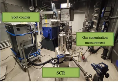
The exhaust gas management system is tested under engine bench dynamometer with laboratory conditions, the main units located in the room (Figure 1):
the exhaust gas treatment system to be tested with the associated diesel engine,
soot particle number counter,
exhaust gas concentration measuring equipment,
the AdBlue injection unit ,
and other sensors (eg. temperature sensor).
Figure 1: Location of exhaust gas treatment system test equipment; Source: Norbert Bíró
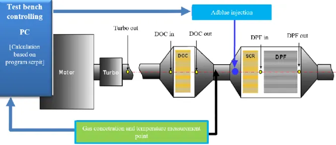
The AVL LD (Light Duty) 220 kW dynamometer is equipped with a PSA DW10c , EURO 5 compliant diesel engine, the exhaust side of which is equipped with an exhaust gas management system widely used by the PSA Group for passenger car engines (Fig. 2.). The AdBlue additive injector is located in front of the SCR catalyst and is connected to the exhaust pipe through a 1/8 inch connector. The injection takes place perpendicular to the inlet surface of the SCR catalyst, so that mixing and chemical transformations can be performed optimally.
DOC DW10c engine
When the test equipment is used in automatic mode, the gas concentration analyzer measures the concentration of the gases in the exhaust gas in real time and transmits them in real time to the dynamometer control computer. From the measured NOx (NO, NO2) concentration, the amount of AdBlue additive required for neutralization is determined, as well as the electrical signal for the valve opening time, which is sent to the AdBlue additive injector at an analog output.
The schematic diagram illustrates the structure of the exhaust gas treatment system, together with the measurement and intervention points.
Figure 3: Schematic diagram of a test system; Source: Norbert Bíró
AdBlue dosing unit design
The main component of the dosing unit is a stainless steel tank (X3CrNiMo17-13-3). The tank has a mean diameter of 300 mm, a height of 500 mm and a wall thickness of 3 mm (Figure 4). With these dimensions, store the liquid at a nominal pressure of 2 bar with a double safety factor. The possibility of filling and refilling the tank can be solved through the roof plate on the top, which can be locked / unlocked with a threaded clamp, thus allowing quick and easy use. After the mains air supply has been shut off, the tank pressure can also be reduced by means of a pressure relief valve on the roof plate for refilling, storage or overpressure. The pressure gauge was also located on the roof plate. To check the level of AdBlue liquid in the tank, a vertical transparent plastic tube has been installed, which is connected to the tank via a 1/8 inch connector [19].
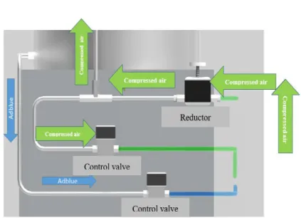
The flow of the various media is controlled by electrically controlled solenoid , normally closed valves.
The connectors are made of ¼-inch brass and are resistant to dissolved ammonia. Figure 5. clearly shows the flow direction of air and Adblue, the traversed path. The reducer-controlled compressed air is split in one
“T” passage and provides the supply pressure to the tank on the one hand, and supplies compressed air to the venturi pump of the injection nozzle on the other.
Through flexible Teflon tubes that are resistant to dissolved ammonia, both air and AdBlue fluid enter a three-port Nippon control TFA-R4 type solenoid valve. The valve works on the Venturi principle. The compressed air flowing through the upper line creates a negative pressure, so it carries the AdBlue fluid coupled to the lower line. Injection can be stopped by closing the valve, while the injection volume can be controlled by changing the opening time of the valve.
Figure 4.: AdBlue dosing unit;
Source: Norbert Bíró
Figure 5.: Compressed air and AdBlue pipe lines; Source:
Norbert Bíró
Injection control principles
The three 24-volt solenoid valves are powered by a 230V to 24V DC adapter. For commissioning, the toggle switch labeled “POWER” [1.] must be toggled to power the controller (Figure 6). The injector opening frequency can be set with knob [2.] After setting, the injector can be started with the rocker switch [3.] marked
"START / STOP". In the start position, the cyclic opening and closing of the injector starts at the set frequency. The process continues until the toggle switch is turned to the "STOP" position. Toggle switch [4.]
"EXT / INT" can be used to toggle between internal, ie control as described, and control based on an external analog signal source (AUTOMATIC). When the equipment is used in automatic mode, the gas concentration analyzer measures the concentrations of the gases in the exhaust gas in real time and transmits them to the dynamometer control computer. Based on the control program, the computer determines the amount of AdBlue additive to be injected and the required valve opening frequency.
Figure 6. Control Panel; Source:Norbert Bíró Control program script
The program had to ensure that no injection was performed below the minimum gas temperature of 180 °C required to convert AdBlue to ammonia. Prohibiting injection is especially important at low temperatures, as AdBlue does not contain pure ammonia. When ammonia is injected, it is formed from AdBlue by a hydrolysis / thermolysis reaction. Because both pure ammonia and AdBlue pollutants cannot escape to the ambient air from the exhaust system.
3. Measurement process and results
To test the AdBlue dosing device, the engine placed on the dynamometer implemented the driving cycle shown in Figure 7, so that the operation of the dosing device could be tested at several operating points. The engine and exhaust system are warmed up in two stages. In the first step, run for 10 minutes at 1500 rpm with a load of 50 Nm. This was followed by the second stage with a 12-minute run at 3000 rpm and a load of 180 Nm. The warm-up phase was followed by three load phases with flight times of 2.5, 1.7, and 1.3 minutes. The speed values varied negligibly for the load sections, and the torque values were 220 Nm, 260 Nm, and 295 Nm, respectively. The last load phase was followed by a 10-minute cooling phase running at 1500 rpm and a load of 50 Nm.
Figure 7.: Dosing test cycle; Source: Norbert Bíró
Figure 8 shows the gas concentration before and after the SCR catalyst. It can be stated that NOx reduction is the most efficient in the low and medium load stages, here it neutralizes up to 99% of the harmful gas.
At high loads, the efficiency drops to 75%, which results in nominal values (max: ~ 370 ppm) under the current regulations of EURO VI. At high loads, fuel consumption increases, proportionally to the amount of intake air, and thus the exhaust gas mass flow.
It can be seen that in the case of long-term use at high loads, the amount of AdBlue injected can be increased by increasing the supply pressure of the container and by using a larger diameter injection nozzle.
4. Conclusions, suggestions
During the preliminary and final tests, the device functioned properly, fulfilled the set goals, and performed the planned functions:
NOx neutralization, min. 80% efficiency over the entire test cycle.
Manual injection setting option, which allows simulating malfunctions in static tests and ExFm (extreme failure mode) tests, thus preventing them.
Automatic use with ANR (Ammonia Nitrogen Oxide Ratio) 1: 1 settings, which fully corresponds to the operation of NOx reduction systems (SCR) in standard passenger cars, making it easy to simulate
all diesel particulate filters manufactured in accordance with the EURO 6d-temp directives after 09.09.2017.
No error has occurred since the device was used.
Figure 8: Dosing test cycle; Source: Norbert Bíró
Further development opportunities
Examining the NOx reduction diagram clearly, it can be seen that in the lower load regions the reduction reaches 99% while in the parts with maximum load the reduction efficiency decreases up to 75%. The output voltage is maximum at these stages, i.e. the solenoid valve operates at the maximum opening frequency, in order to increase the amount of AdBlue injected and thereby increase the reduction efficiency, the following improvements must be made:
Increase the inside diameter of the injection nozzle or use another nozzle with a larger inside diameter for higher load tests.
Increase the maximum tank supply pressure from 2 bar to 4 bar, which would not endanger the operation of the appliance. This would increase the amount of Adblue injected, which would increase the reduction efficiency.
These development opportunities would require new tests, but a correspondingly increased AdBlue injection could also open up the possibility of testing more powerful car and truck engines.
References
[1] Seher, D., Reichelt, M., and Wickert, S., (2003). Control Strategy for NOx - Emission Reduction with SCR. SAE Technical Paper 2003-01-3362, https://doi.org/10.4271/2003-01-3362.
[2] Keuper, A., Unger, H., Huang, J., Bressler, H. et al. (2011). Investigations to Achieve Highest Efficiencies in Exhaust Gas After-Treatment for Commercial Vehicles using an SCR System. SAE International Journal of Commercial Vehicles. 145-155.
[3] Kazushige O., (2006). A Study on performance of Performance of Particulate filters Using R-SiC Porous Materials for Diesel Vehicles. Scientific textbook. 2.1 – 3.45
[4] Birkhold, F., Meingast, U., Wassermann, P., Deutschmann, O., (2006). Analysis of the Injection of Urea-Water-Solution for Automotive SCR DeNOx-Systems: Modeling of Two-Phase Flow and Spray/Wall-Interaction. SAE Technical Paper 2006-01-0643, https://doi.org/10.4271/2006-01-0643.
[7] Daimler-Benz Ag. (1998). Method and device for operating an internal combustion engine with low nitrogen oxide emissions. Patent.
[8] Man Nutzfahrzeuge Ag. (1993). Catalytic nitrogen oxide(s) redn. appts. for vehicles - comprises flow mixer urea evaporator hydrolysis catalyst, for exhaust gas treatment. Patent.
[9] Jánosi, L., Kiss, P. (1988). Belsőégésű motorok nitrogénoxid kibocsátásának követése más motorjellemzőkből. MTA-MÉM Agrár-Műszaki Bizottság kutatási és fejlesztési tanácskozás Gödöllő, Magyarország : MÉM Műszaki Intézet, 34-36.
[10] Ford Global Technologies, Inc. (2002). Method and system for NOx reduction. US Patent.
[11] Haldor Topsoe A/S.(2003). Process for the reduction of SCR NOx emissions and apparatus therefor.
Patent.
[12] Gabrielsson Par L.T. (2004). Process for controlled addition of a reducing agent into nitrogen oxides containing exhaust gas. Patent.
[13] Ford Global Technologies, Llc. (2006). Exhaust gas aftertreatment systems. Patent.
[14] Robert Bosch Gmbh. (2010). Procedure for checking the functionality of a metering valve of a NOx- reduction system of a combustion engine. Patent.
[15] Hilite Germany Gmbh. (2012). SCR exhaust gas aftertreatment device .Patent.
[16] Robert Bosch Gmbh. (2015). Vehicle SCR system and its reducing agent supplying device. Patent.
[17] Zheng, G., Wang, F., Zhang, S., Zhang, J. et al., Development of Compact SCR Systems with Closely Coupled Injector Configurations. SAE Technical Paper 2014-01-1546, 2014, https://doi.org/10.4271/2014-01-1546.
[18] European comission, emission regulation directive https://eur-lex.europa.eu/legal- content/EN/TXT/?uri=CELEX:32016R0646 ; https://eur-lex.europa.eu/legal-
content/EN/TXT/?uri=CELEX:32008R0692 ; https://eur-lex.europa.eu/eli/reg/2018/1832/oj
[19] Bíró, N., Pillinger, Gy., (2020). AdBlue-adagoló fejlesztése kipufogógáz-kezelő rendszer optimalizálásához. Mezőgazdasági Technika 2020. május : LXI. Évfolyam.. 2-5.
[20] Szőllősi, D., Bíró, N., Kiss, P., (2020). A dízel részecskeszűrő (DPF) koromszűrési hatékonyságának megállapítása. Mezőgazdasági Technika 2020. szeptember : LXI. Évfolyam 2-5..