SOLAR CONCENTRATION ASSOCIATED WITH THE STIRLING ENGINE1
R. E. Henderson and D. L. Dresser' 2 Allison Division
General Motors Corporation Indianapolis 6, Indiana ABSTRACT
Progress in the development of a lightweight solar concentrator for the Stirling engine power system is reviewed. The preliminary study activity which led to the selection of an all-metal Fresnel reflector component is given. Reasons for choosing the Fresnel configuration are listed. The optical performance of the modified Fresnel reflector is presented - this includes the ideal intensity distribution, the lost area factor, and some estimated solar collector efficiencies for both the Stirling engine application and a thermionic system. The electroforming fabrication method being developed is described. Finally, experi- mental results from two 40.b cm diameter model reflectors are evaluated for the concentration performance.
INTRODUCTION
If a solar-to-electrical power system using a Stirling engine prime-mover is eventually going 1. Presented at the ARS Space Power Systems
Conference, The Miramar Hotel, Santa Monica, California, September 27-30, 19ö0.
2. Chief Applied Physicist - Research Department 3. Head - Physics Section - Research Department
to operate in space, then a suitable lightweight solar concentrator must be developed during the next few years. A preliminary study of the gen- eral problem of concentrating solar energy for a space power application revealed that there was no technology presently available which was satis- factory for these new applications. Since there was no state-of-art in the field of solar collect- ors a further study of the solar collector require- ments for the Stirling engine was made in order to select a concentrator configuration for component development. A modified Fresnel reflector geometry fabricated by electroforming techniques was chosen as the most promising development approach. This paper describes the progress which has been made in the development of a lightweight Fresnel re- flector for the Stirling engine. The objective of the development program is to fabricate a lightweight, all-metal reflector with satisfactory optical performance for the Stirling engine
application.
BACKGROUND
The advanced Stirling cycle engine is an external combustion gas cycle engine with very high thermal efficiency. It is described in de- tail in Ref. 1 and 2. Due to its high efficiency, external combustion characteristic, simplicity of operation, and low vibration it is under develop- ment as a heat to mechanical energy converter for
solar satellitic electric power supplies. A schematic for the overall system is shown in Fig.
1.
The solar collector is made up of a reflector and cavity absorber. The temperature of the
cavity absorber determines to a great extent the collector efficiency since reradiation losses are proportional to the cavity temperature to the fourth power. The cavity temperature in turn is determined by the thermal energy storage material selected. Many studies have shown that LiH is by far the best material for this application due to its extraordinarily high heat of fusion
(2Ö00 kw-sec/kg). Therefore, the melting
point of LiH, 950βΚ, must be attained by the absorber; and the absorber temperature must then be 960*K to take care of temperature drops through the cavity and LiH container walls. A preliminary design of the absorber is presented in Ref. 3.
If continuous power is not required or if the vehicle is to be in the sun continuously then the requirement for operation of the absorber at 96θ°Κ is removed. However, most missions thus far
studied have required energy storage and, as a re- sult, the melting point of LiH has become an established point around which system design has been built up for the Stirling engine.
The problem of solar concentration has thus centered around the development of a reflector which can most efficiently focus solar radiation to a cavity at 96θ*Κ. The problems to be con- sidered may be listed as follows:
1. High optical performance 2. Low weight
3. Mechanical design to withstand the mission environment
4. Low storage volume
5. Reliable erection mechanism
6. Material resistance to space environment 7. Low cost
Of course, one cannot expect to develop the ideal collector which would possess the ultimate performance as indicated by each of these items.
Rather, there is considerable interplay between these characteristics which the designer must eventually resolve by optimum compromises. For example, some reduction in optical performance may be possible in order to obtain a lower weight.
On the other hand some increase in weight may be advisable in order to improve the material re- sistance to space environmental factors.
Since there was really no state-of-the-art in the field of solar collectors for space, an initial study of the problem was made by reviewing the available literature and design practices in some related areas as follows :
• Solar furnace theory and practice
• Terrestrial solar energy utilization projects
• Design and fabrication of large search- lights
• Other space research projects Ref. 4 presents the details of this study.
Allison engineers in the experimental process development department were consulted concerning special fabrication techniques which might be applied in the construction of a solar collector.
In addition, people who manufactured fabric mater- ials, coated plastic films, foamed plastics, etc., were contacted in order to ascertain the applic- ability of these materials for a solar reflector in space. Information derived from these activ- ities was evaluated using the seven characteris- tics given above as "ideal" criteria. In this way an engineering approach to the design and develop- ment of a solar collector component for the
Stirling engine APU was selected.
It was concluded that a Presnel reflector together with a cavity absorber had the best po- tential for an optimum solution of the solar con- centration problem. In Ref. 5* Trombe discusses the possible advantage of the Fresnel optical geometry for a large solar furnace. The major factors which determined this decision were as follows :
i) a low weight, all-metal construction for the reflector appeared possible.
ii) the flat plate geometry would permit a variety of folding designs for storage.
iii) a simple, reliable mechanical erection device could be employed (springs, hinges, dash-pot dampers, etc.).
iv) a high optical performance could be
achieved by utilizing a precision pattern, by accurately aligning the reflector
sections in the deployed condition, and by reducing the thermal distortion with a single metal construction.
v) an all-metal construction promised the best resistance to certain elements of the space environment (micrometeorites,
ultraviolet radiation, and solar flares).
vi) with a reflector consisting of rigid sections it would be convenient to per- form many types of tests, such as, de- ployment cycle testing to establish the accuracy performance and reliability, and pre-flight tests for check-out before launch.
It was the general conclusion after completing the preliminary study that the first generation re- flectors would probably be of rigid construction.
A rigid reflector composed of sections appeared feasible for diameters up to approximately 10-12 meters; the exact diameter would depend upon the storage volumes available as well as the capability of the fabrication technology developed. From preliminary studies of the 3kw Stirling engine system the reflector diameter was calculated to be well within this limit.
PRESNEL OPTICAL PERFORMANCE
The major factors in determining the actual performance of any solar collector design are the nature and magnitude of reflector surface errors which cause the reflector to deviate from the
ideal geometry. These surface errors arise from three sources -
1. Fabrication methods and manufacturing tolerances
2. Transient and steady state thermal grad- ients
3. Erection and assembly tolerances
If the solar reflector geometry differs greatly from the ideal geometry chosen for the collector design, then the energy reflected to the focal plane is scattered over a large area. As a con- sequence, the heat absorber area in the focal plane
(cavity opening or selective surface) must be increased to intercept the incoming energy. An increased absorber area means more energy is lost due to reflection and reradiation. In addition, the absorber design may be complicated by the resultant heat transfer requirements.
Ideally, the solar collector designer desires to know the intensity distribution in the focal plane of the reflector. If the actual intensity distribution is known, then an optimum absorber area may be determined for any specific design.
The optimization criterion is -
• No area of the absorber surface should intercept any incoming radiation which results in more power being reflected or reradiated than is absorbed.
Of course, the best way to determine the actual intensity distribution is to measure it after the reflector is built. However, this approach is expensive and time-consuming. The necessary re- search and development work must be accomplished to demonstrate good agreement between the inten- sity distributions obtained by theoretical analysis and the distributions measured experimentally on model reflectors. Then the designer may proceed with confidence on the design of solar collectors for space applications. Further, it is only after such a meaningful correlation of theory and
experiment has been achieved that the future capabilities and ultimate limitations of solar- powered auxiliary power systems for space can be ascertained.
In this section some theoretical work on the Fresnel reflector is discussed.
The Modified Fresnel Reflector
The Fresnel reflector approaches the per- formance of the paraboloidal reflector. The Fresnel consists essentially of a flat plate with a number of concentric rings as shown in Fig. 2.
Each ring, or serration, is cut at a different angle so that all incident parallel light is directed towards a common focal point. There is some choice in the design of the Fresnel serrations.
For the highest performance each serration should be a section from a paraboloid; the paraboloids would have differing focal lengths depending upon the radial position of the serration. When mounted on a flat plate the serrations would have a
common focus; this type of reflector is known as
the true Presnel reflector. Modified versions of the Presnel can be fabricated by making the surface of each serration spherical or conical.
Study of various manufacturing processes has indicated that the conical surface is the easiest to fabricate with a resultant reduction in re- flector cost. Later, it will be shown that, if a large number of serrations are employed, the loss in performance is small. The Fresnel re- flector with conical serrations is known as the modified Presnel reflector.
Intensity Distribution for an Ideal Modified Fresnel Reflector
A detailed optical analysis of the modified Presnel reflector was initiated with the objective of developing a method of calculation to predict theoretically the actual intensity distribution.
The following discussion is intended to outline the analytical approach and to present the re- sults to date.
Figure 3 defines the pertinent geometrical quantities. Three assumptions are made for the
study: t h
1. The distance from any point on the n segment to the corresponding point in focal plane is constant and given by the mean value.
2. The solar disk is circular and uniform in intensity, so that the rays from each infinitesimal area of the n ™ serration form an ellipse of uniform intensity in the focal plane.
3. The ray from the center of the solar disk is the center of the ellipse in the focal plane.
For purposes of integration the reflector is
divided into two regions, I and II, by a reflector diameter as shown in Fig. ^. Each serration is further subdivided into regions I_ and II__ on one side of the serration center circumference and 1+ and 11+ on the other. A point on the reflec- tor is related to a corresponding point on the focal plane by:
(For the + region) R = R + r Cos G>
n n (1)
(For the - region) R = R - r Cos 0
v σ n n
An infinitesimal projected area of the serration is given by:
dA = R(dR)(dß) (2) The energy reflected by this infinitesimal area is:
dE = nrEgR (dR)(dß) (3)
This energy is uniformly distributed over an ellipse in the focal plane of area:
Ae = V4 ( Pna)(pna/cos 0n) (4) Thus, dividing (Eq. 3) by(Eq. k) , the intensity
contribution on the focal plane is found:
E = 4ηΓ Es cos 0n R(dR)(dß) ( 5 )
π(ρηα)2
Equation (5) is then integrated over the useful area of the serration which contributes to the intensity at a given point, P, in the focal plane.
In general, the resultant expression for the n^h serration is:
En = 4η EB cos 6n ( ) + ( I ) + (II+)+(lI )
~w^ (6 ;
where
τ±
= A^a I±iV
r cos QJ*
COS Qn)(
d r^
d ß)
I X ± - Area;Îl±(Rn * r c o s Qv) <* COB 0n) (dr)(dß)
Absolute values are used to insure that the in- tensity contributions from each region will add.
A major problem associated with the solutions of these integrals is the determination of the limits on each integral. These limits are obtained by considering the ellipses in the focal plane formed by light reflected from the various differ- ential areas, dA. Por example, in the case where
F^p cx/2 cos 0 the important limiting ellipses are shown in Pig. 5. If P> Pn + Pnct/2 cos 0n, then the intensity is zero. If P<p a/2, then the in- tegrals of Eq. 6 have the follBwing limits:
I, = /+ TT/2 dß /^+(R + r cos 0) cos 0^ dr (7a)
"π/2 ° n n n
I. =/_V2 dß /r"(Rn + r coà Qn)(-cos O j dr (7b)
~Tr/2 o
11.=/
• "■— /o o n n n TT/2 dß
f^~(K+
r cosO
cos Q~
dr(7c)
7Γ/£
H_=/_V2 de /r +(Rn - r cos 0n) (-cos 0n) dr (7d) ττ/2 μ o
where
r± = P cos β ± sec 0 V n ν(ρηα/2)2 _ (Ρ3ΐηβ); The expressions for r+ and r_ are determined from Fig. 5. The integrals are evaluated analytically.
The resultant intensity expressions are programmed for solution on a digital computer. The analytical approach was repeated to treat successively smaller values of F, which may be interpreted as allowing successively smaller serration lengths.
Figures 6, 7 and 8 show some typical results for 50 and 100 equal length serrations at aperture ratios of 1.0, 1.5, and 2.0. The intensity dis- tribution for the ideal paraboloid is included for comparison. Note that the ability to concentrate the energy into a given area in the focal plane is approximately equivalent for the two geometries.
However, the intensity values for the paraboloid are higher than the Fresnel. There are two reasons for this difference - (l) the flat surface of the Presnel serrations is an approximation to the corresponding curved surface of the paraboloid, and (2) the total energy reflected to the focal plane by the Fresnel is less than the total energy reflected by a paraboloid of equal focal length because there is some lost reflector area in the Fresnel design. While the results given are for
equal length serrations the possibility exists for obtaining approximately the same concentration performance with a lesser number of different length serrations, i.e., larger serrations near the center of the reflector and smaller ones near the rim.
Surface Area Efficiency
Some of the Fresnel reflector area is wasted due to blockage between the adjacent serrations.
The surface area efficiency, Tf, is defined as the ratio of useful area to total reflector area.
For a constant length serration Tf is a function of the number of serrations and the aperture ratio.
In addition, the fabrication of a given reflector design may require a minimum dimension for bonding the reflector surface to a support structure; this requirement can increase the waste area. Study has shown that if 50 or more serrations are used, Tf is independent of the serration number. With this assumption Fig. 9 shows the relationship between Tf and aperture ratio.
Prediction of Actual Performance
In order to optimize the actual performance of the Fresnel reflector the intensity distribution must be calculated with realistic surface errors included. In the analytical approach discussed previously the theoretical distribution can be calculated for a serration angular error with no circumferential dependence. Attempts to make the solution more general resulted in complicated integrals solvable only by numerical methods or simplifying assumptions. The gross serration angular error appears to be the most likely error which will be present. Although there will be some "waviness" of the serration surface and also
circumferential variations of serration angle, it is felt that these variations will be of second order magnitude compared to errors arising from assembly, erection, and thermal effects. At the present time no results are available from the theoretical work considering the non-ideal re- flector. However, it is planned to solve for the distribution with various assumptions on the
angular error function, such as, a normal function
and a weighted function dependent upon radial position. Experimental results will ultimately determine the best error function for purposes of analytical studies.
Since the actual intensity distribution as predicted by the analytical method outlined above has not been obtained as yet, a conservative approach may be used to estimate the performance.
The conservative approach assumes that the absor- ber area is made large enough to intercept all of the energy incident upon the focal plane, and simply involves a straight-forward ray tracing technique. Figure 10 is used to formulate the necessary performance equations, assuming all Presnel elements are of uniform length, L. L may be related to the reflector diameter as follows:
DR = 2 mL (8)
A consideration of the ray geometry shows that:
D
R =
2Pm
sin Qm W
AR = 7TPrn2 sin 2Q ( 1 0 )
pa m 2 p φ _
D
H -
2< ττότ^
+τ ^ τ <-%-) (»)
Au = πρ 2 a + 4</> s i n 0w 9 / ,Qx H rm / m + m_ \à [lé)
% ^cos 0w m '
In order to determine the solar collector m efficiency with a modified Fresnel reflector, it is necessary to solve the heat balance equation for the absorber cavity expressed as follows:
e c W 8 * R = Q + ΑΗε θ ΤΚ4 (13) The quantity on the left hand side of(Eq. 13)
represents the total energy entering the cavity per unit time. The right hand side contains two terms — one, the heat power which is absorbed by the power converter and, two, the amount of heat that is reradiated from the cavity inlet area.
If the solar collection efficiency is de- fined as :
n c - fr <*>
then by proper substitution with (Eqs. 10, 12, and 13) the efficiency may be expressed as:
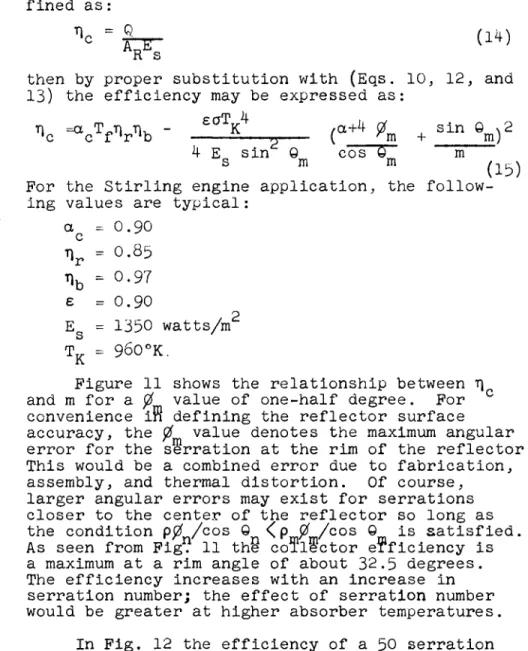
Ώ =α Τ-η Τ) -•c c f 'r 'b n { ε σ ΤΚ4 /a+4 ti , sin 0*2 rjn + m j 4 E sin 0 cos 0_ m
s m m ( 1 3 )
For the Stirling engine application, the follow- ing values are typical :
a - 0.90 η* = 0.85
% - 0.97 6 =0.90
E = 1350 watts/m2 τκ = 960°κ.
Figure 11 shows the relationship between η and m for a 0 value of one-half degree. For convenience iff defining the reflector surface accuracy, the 0 value denotes the maximum angular error for the serration at the rim of the reflector.
This would be a combined error due to fabrication, assembly, and thermal distortion. Of course, larger angular errors may exist for serrations closer to the center of the reflector so long as the condition pp /cos 0 <Pmfim/cos Qm i s satisfied.
As seen from Fig. 11 the collector efficiency is a maximum at a rim angle of about 32.5 degrees.
The efficiency increases with an increase in serration number; the effect of serration number would be greater at higher absorber temperatures.
In Fig. 12 the efficiency of a 50 serration reflector is shown as a function of rim angle for 0 values of 0.25°, 0.50e, and 1.0°. The efficiency decreases rapidly as the surface
quality of the reflector decreases. Also the rim
angle for maximum efficiency shifts to lower rim angieß as the precision of the reflector increases.
To illustrate the effect of absorber temp- erature upon the efficiency of the collector, the same conditions as used for the Stirling engine were assumed except that TK = 1500€K.
These conditions would be typical for a solar thermionic application. Figure 13 summarizes the results for a 100 serration reflector. In comparing the results of Pig. 12 with those of Fig. 13, the requirement for a higher quality reflector in the thermionic application is shown.
FRESNEL FABRICATION APPROACH
After a careful study of various manufactur- ing processes which might be applied in fabricat- ing a solar reflector for space applications, it was concluded that such a structure could best be obtained by electroforming techniques. There are a number of advantages to the electroforming approach; namely,
• Massive, rigid patterns can be machined accurately
• Very thin, stress-free reflecting surfaces can be realized
• An all-metal construction is possible
• A single master pattern can be used to make several reflectors
The general fabrication approach was to electroform a thin foil of metal on an accurately made replica of the Fresnel surface. Then with
the foil still in position on the pattern the support structure was attached. The whole assem- bly would then be removed from the pattern and coated with a high reflectivity surface.
Figure 14 shows a pattern for a small model modified Fresnel reflector. Nickel was selected for the electroforming material as it has good physical and mechanical properties, is highly resistant to corrosion, and can be plated with a low residual stress level. Figure 15 shows an
electroformed nickel surface made from a sample pattern. The pattern had a reflectivity of 65$
and the electroformed nickel surface (the dark section on the sample) had the same reflectivity.
The bright section on the sample is vacuum plated aluminum on the nickel surface; a surface reflect- ivity of 90$ was measured.
Various reflector supporting structures have been investigated. The most promising design consists of a lightweight frame-work with a grid to attach the nickel foil. The grid and supports are electroformed nickel. Figures l6 and 17 illustrate the type of construction. Bonding is accomplished by ultrasonic welding; this bonding method adds no weight to the assembly.
Pattern requirements for the reflector depend upon the folding design for storage. Typical folding methods which have been studied are shown in Figs. 18 and 19. Figure 19 is the storage design which was proposed for the NASA - Sunflower I project.
EXPERIMENTAL RESULTS
As a part of the development program to in- vestigate various fabrication methods for making Fresnel patterns, several 40.6 cm diameter patterns were fabricated. These patterns could then be used to study other fabrication problems, such as, assembly, bonding, vacuum plating, etc. The dimension of 40.6 cm was chosen as a convenient size to fit the vacuum plating facility. The pertinent optical data on the 40.6 cm diameter model are as follows:
Diameter - 40.6 cm Focal length - 24.2 cm Rim angle - 40"
Number of serrations - 27
Figure 20 is a picture of one model reflector made from an experimental pattern. The reflector was made in four parts and could be folded as shown in Fig. 21.
The scattering distribution for the model was obtained utilizing the test set-up shown in Fig. 22. Basically,, the procedure consisted in directing a small beam of collimated light parallel to the optical axis, onto the reflector and de- termining the location of the reflected ray in the focal plane by means of a sensing device.
The reflector was checked at five different radii and several circumferential positions at each radius. The collimator was designed to produce essentially a parallel light source. The sensor system consisted of a solar cell, a three
dimensional vernier, a vernier mounting arm, an amplifier, and a voltmeter. With the collimator set at a given radius the sensor was moved in the focal plane until the location of the reflected ray was determined by a peak reading on the volt- meter.
Figure 23 shows some scattering data obtained from the model. Although the number of data
points recorded does not represent an ideal sample for determination of the scattering distribution, the fifty-one points taken over five radii positions are sufficient to make a preliminary estimate
of the concentration performance. From Fig. 23 it can be seen that the majority of the points are located near the center of the focal plane. Most of those points farther from the center originate from the larger radii serrations. Also the
scattering distribution does not appear to be uniform with circumferential location. This data may be used to estimate the concentration factor, where the concentration factor is defined as the ratio of the total reflector projected area to the total area intercepting energy in the focal plane. By the ray tracing method the concentra- tion factor can be computed from the following
E q·: = sin2 2 Qm
/ ^ uni "\ sin 20 N2 (l6)
(a + i ^ + m)
The ideal concentration factor ($ = 0) is 2m calculated to be 1260. The value of pnj for the
the scattering circle diameter. The 0 value is 60.5 minutes; this corresponds to a concentration factor of 98. Another reflector with the same dimensions but in a single piece was made of plastic. The scattering data for this reflector is shown in Fig. 24. The concentration perfor- mance of the plastic reflector is seen to be much better than measured from the electroformed model.
Prom the observed scattering diameter in Pig. 24 a 0 value is l8.8 minutes; this corresponds to a concentration factor of 400.
Since there was no special effort to obtain accurate alignment of the four piece electroformed model, the above data shows quite conclusively
that the poor performance of the electroformed model was due to inaccurate alignment of the reflector sections. Thus, these data serve to emphasize one of the major design problems in obtaining suitable Presnel reflector components although reflector sections with high optical accuracy may be fabricated by the electroforming technique, the actual performance of a déployable reflector will be determined by the accuracy with which the sections can be assembled.
CONCLUSIONS
The following conclusions can be made based upon the theoretical and experimental work to date on a Presnel reflector component of the solar collector assembly for a Stirling engine appli- cation:
1. A 50 serration Fresnel reflector with a ti value of one-half degree and a rim angle between 30-40 degrees has satisfact- ory optical performance for a solar power- ed Stirling engine application.
2. Experimental results to date indicate that electroformed surfaces for the modified Presnel geometry can be fabricated with an angular accuracy of less than ten minutes and with a surface reflectivity to solar radiation outside the atmosphere of greater than 85$.
3. It appears that the major factors in determining the optical performance of déployable electroformed reflectors are the accuracy of individual section assem- bly, and the alignment of the several sections to form the complete reflector.
NOMENCLATURE
A - differential area on the Fresnel surface A - area of ellipse projected onto the focal
plane
AH - area of cavity inlet opening
AR - projected area of the Fresnel reflector C - concentration factor
E - intensity (w/m ) p
E - solar constant
F - radius of the image in the focal plane due to parallel light
L - serration length N - aperture ratio
P - point in focal plane
Q - heat input to power converter (watts) R - radius position on the reflector
Tf - Fresnel useful area factor Tv - cavity temperature
d - diameter of the solar image (d = fa) f - focal length
m - number of serrations n - serration number
r - radial position in focal plane a - angular measure of solar disk a - absorptivity
ß - circumferential angle in the focal plane
emissivity blockage factor collector efficiency reflectivity
angle between the optical axis and the n th serration
rim angle
radius distance from n serration to focal plane
Stephan-Boltzmann constant
angular error of the n serration angular error of the rim serration REFERENCES
1. H. W. Welsh, E. A. Poste, and R. B. Wright, The Advanced Stirling Engine for Space Power, American Rocket Society, Paper No. 1033-59,
(1959).
2. M. D. Parker and C. L. Smith, Stirling Engine Development for Space Power, American Rocket Society, Paper No. 1315-00, (i960).
3. C. L. Walker, J. D. Matchett, and R.J. Harold, A Storage System for Satellite Power Plants, American Rocket Society. Paper No. 1041-59,
(1959).
4. D. L. Dresser, Elements of Solar Collector Design, Institute of the Aerospace Sciences, Paper No. 61-24, (l96l).
5. F. Trombe, "High Temperature Furnacesn,
Proceedings of the World Symposiun on Applied Solar Energy, Stanford Research Institute, Menlo Park, California, 1-5 November 1955, Page 63.
% -
\ - Θ *r n
Pn -
0 -
S O L A R
eu ERG, y COLLECTOf
THERI^AU ENCRCY
E N e R Q y STORAQE
T H E R M A L E M i R û Y
S T I R U M G G N G i N e
MEC H.
ENKRCaY
W A S T E H C A X
e i . c c T . E N E R d y
W A S τ ε
L O A P
1 H E A T r
R A D I A N T E N E R G Y X o S P A C E .
Satellitic Solar Stirling System Schematic
2. The Modified Fresnel Reflector
♦ t
T
F-t
Uröh
M..-I
\-WASTE AREA
l·—u—4-—UTH
3. Modified Fresnel Reflector Geometry
fr-rF^
Defining Geometry for Evaluating Integrals
5. Geometry for Determining Integral Limits
Kl = l.o
PARABOUOvO
6. Ideal Intensity Distribution for N - 1.0
7. Ideal Intensity Distribution for N = 1.3
N = £.°
P A R A B O L O I D
ί
4 ο.β|
UI
<
D °·71
li. UJ
Ι.Ο 2 . 0 A P E R T U R E R A T I O
3 . 0
Ν
Waste Area Versus Aperture Ratio
Λ.Ο
tosG
10. Fresnel Optics Diagram for Ray-Tracing Method
vs.
0
υ z
W 5 5 f
5 0 J
U. Ü.
UJ
a o h Ü
UJ -J
Δ
0 o
4 5
4-CH
3 5 I
O
m = l o o
IO 2 0 R I M
3 0 4 0 A N G L E Θ *
TO G O 7 Ό
11. Solar Collector Efficiency as a Function of Serration Number
\Φ
4ο\
2 0 3 0 4 0 SO <bO z o
G>o + F O R m = l O O
5<H
Ά,Φ
4o+30 +
20+
A n = *
101 \o so 3 0 4 0 s o
0 ^ CDeceees^) <ôo T O
13. η for a Thermionic Application
14. A Fresnel Pattern
15. Electroformed Nickel Sample
Ib. Fresnel Reflector Sample - Front Side
17·. Presnel Reflector Sample - Back Side
l8. Storage Design - Pie Shaped Fold
FRESNEL SURFACE.
1V
FOLOEO-TOP VIEW FOLDED- SlOE VIEW
19. Storage Design - Hexagon Fold
: &
SfK-.·
·-&*&*
Vy \
21. A Model Fresnel Reflector - Folded Position
22. The Test Set-Up
SPACE POWER SYSTEMS
(0::?:
2 0 Soi fr a
J 0 r in © ϋ 5 15
0 O □ + *
* Θ r, + D o x
s9 (M 0 in « 0 0 ιί> M « s9 *
^VM)
249
SPACE POWER SYSTEMS
<§ O - -
« 0 5 ? 3
0 O □ + *
* G
<p
Q□
CM in in (u-IUÎ) CD
25Ο