Reactor Failure due to Resonance in Zahedan- Iranshahr Parallel EHV Lines, Analysis and Practical Solutions
Mohammad Hamed Samimi
1, Moien Abedini
1, Amir Hossein Mostajabi
1, Davood Farokhzad
2, Hossein Ayoubzadeh
2, Amir Abbas Shayegani Akmal
1, Hossein Mohseni
11High Voltage Research Center, School of Electrical and Computer Engineering, University of Tehran, North Kargar Avenue, IR-14395, Tehran, Iran
2High Voltage Transmission System and Power System Protection Office, Iran Grid Management Company, Yasemi str., Vali-asr str., 1996836111, Tehran, Iran m.h.samimi@ut.ac.ir, m.abedini@ut.ac.ir, ah.mostajabi@ut.ac.ir,
farokhzad@igmc.ir, ayoubzadeh@igmc.ir, shayegani@ut.ac.ir, mohseni@ut.ac.ir
Abstract: A reactor winding has been damaged due to induction of resonance voltages on the de-energized circuit of two parallel 230 kV shunt compensated lines between Zahedan and Iranshahr. The phenomenon is modeled in PSCAD and the safe range of shunt compensation is derived. In this study the effect of various faults on the lines, the reactor saturation and corona dissipation are considered and the results are compared to the electrostatic no-loss method results. Various ways are examined for damping the resonance condition and the best solution is chosen.
Keywords: resonance; PSCAD; shunt reactors; transmission line modeling
1 Introduction
Shunt reactors have many applications in extra high voltage transmission lines and using them has some challenges [1-7]. For example, the application of shunt reactor compensation to one or more circuits of mutually coupled multi-circuit overhead transmission lines requires special considerations beyond those ordinarily required for single-circuit lines as a result of voltages which may be coupled from one circuit to an adjacent circuit. This is particularly true when two lines are completely or partially untransposed [8, 9]. Previous measurements revealed that unusually high voltages and currents were experienced by the reactors when their associated circuit was disconnected from the system [10]
which could damage them. Some papers previously developed a matrix analysis
for deriving the general curves which show the resonance voltages versus the shunt compensations [8], [11-15]. Some others have used software like EMTP for studying the resonance conditions [16, 17]. This paper presents the analysis and solutions for a similar situation using PSCAD.
A reactor winding is damaged in Zahedan-Iranshahr double-circuit 230 kV untransposed transmission line which is compensated with two 25 MVAr reactors at each end of the circuit. Figure 1 shows the circuit and the transmission line configuration. First, the Zahedan-Iranshahr line was tripped out by the distance relay because of a fault on that circuit. A voltage of about 15 percent higher than the nominal voltage was observed by the operator in this situation while the parallel line, Zahedan-Khash-Iranshahr line, was still live. By the idea that the voltage is real and because of failure of circuit breakers, the bus bar at Iranshahr substation was de-energized and the Iranshahr-Khash line was disconnected as well. Unfortunately the bottom line had remained in a resonance condition even when one part of the top line was de-energized and only one part of it was remained live, so the voltage was still observed on the first line. Therefore, the bus bar of Iranshahr substation had to be de-energized.
Since only 25 MVAr reactors are available in the short-term in Zahedan power section, damping seems to be a good solution. Using the PSCAD, various conditions are examined for damping the mentioned circuit and the best one is proposed. As well, the safe range of shunt compensation is derived for various lines statuses.
Figure 1
(a) Double-circuit 230 kV system configuration; (b) Double-circuit transmission line configuration
2 The Range of Shunt Compensation for Safe Operation
2.1 System Modeling in PSCAD
For modeling the system configuration, first we used three PSCAD simple reactors in each terminal. In this way we are able to measure the neutral currents and voltages before and after adding elements in the neutral of reactors. For modeling the transmission line configuration we used a PSCAD double-circuit transmission line tower without transposition. The dimension between conductors is the same as the one showed in Figure 1. The ACSR Canary was chosen as a phase conductor type. The sags of phase and ground wires were set to 7.5 m and 5.7 m respectively.
The soil resistivity and shunt conductance of the line have an enormous effect on the level of resulted resonance voltages. Lower shunt conductance leads to higher resonant voltages [16, 18]. A range of shunt conductance from 0.76 pS/km (non- ceramic insulator) to 6.5 nS/km (polluted glass-type insulator) in 230 kV class is reported in previous works [16]. As this transmission line is located in the desert and has ceramic type insulators, the shunt conductance of the line is set to 5 nS/km. In the case of lower values of soil resistivity, higher values of resonant voltages were computed [16]. Because of a sandy soil in the transmission line’s right of the way, a value of 500 Ω.m was selected as the soil resistivity.
20 30 40 50 60 70 80
101 102 103
Shunt reactor rating (MVAr)
Line to ground voltage (kV peak) Phase C Temporary OV
Phase C Voltage Phase B Voltage Phase A Voltage Rated Reactor Voltage
Figure 2
Three phase line to ground peak voltages and phase C temporary peak overvoltage versus three phase shunt reactor ratings: no-fault, the bottom line is opened and the other ones are energized
We put a generator at each terminal of the double-circuit line. These two generators have the nominal line voltages equal to 230 kV. About 60 MW active
power is flowing from right to left due to a small difference between two generators load angel.
The PSCAD has various transmission line solver models. In this case the analysis is for low frequency so the Bergeron model was picked as a solver which is a constant frequency model based on travelling waves [19], [20]. The results from the Bergeron model without damping approximation are with a good accordance with the ones from electrostatic matrix solution explained in the next section, so we used this option of Bergeron solver.
2.2 Analysis with Linear Reactors
Three values of shunt compensations may result in resonance on the opened untransposed line. These resonant conditions can occur in a no-fault condition and during the occurrence of any fault on the energized circuit as well. Faults in the energized circuit may lead to higher values of resonant voltage because of unbalancing, but they won't change the resonant points [13]. However, faults in the opened circuit can result in resonance for other shunt-reactor values. In previous works the faults on both the opened and the energized circuits were analyzed and up to 19 shunt-reactor values can cause resonance on an untransposed line [13].
To find these values, in the first step we changed the shunt linear reactors in a wide range and recorded the three phase line to ground voltages in no-fault condition. Both lines are energized in the first state and then the breakers in the bottom one in Figure 1 are opened and then the steady state line to ground voltages of each phase are recorded. A temporary transient overvoltage is observed after breakers operation anyway. Figure 2 shows the line to ground peak voltages values versus MVAr shunt reactor ratings in no-fault conditions with linear reactor simulation. Also, it contains the peak values of these temporary overvoltages recorded after breaker opening. This figure has a very good accordance with the previous works done by matrix solution [8], [11-14] and EMTP [16].
The corresponding resonant points are 33.3, 44.9 and 48.8 MVAr reactive compensations. The electrostatic analysis results are 30.8, 45 and 50.5 MVAr reactor compensations with the guard wire consideration. These values from the simulation are favorably comparable with the electrostatic no-loss solution. The details of the electrostatic method have been explained in the next section.
Faults on the opened line lead to different resonant points from no-fault ones [13].
Various faults comprise line to ground, line to line and line to line to ground was applied to the opened line and the line to ground peak voltages of the reactors were recorded. These voltages for phase C are shown in figure 3. There are two resonant points in LG fault on phase B: 38.7 and 44.9 MVAr reactive
compensations, two points in LL fault on phases A and B: 33.4 and 45.8 MVAr compensations, and one point in LLG fault on phases A and B: 42.1 MVAr compensation. The results from electrostatic solution are 42.7, 48.9, 31.2, 45.5, and 49.3 MVAr compensations respectively. Regarding to above outcomes, the simulation results are comparable with the ones derived from the electrostatic method.
This procedure should be done for two other situations. In the first one, the bottom line is opened and only one of the top lines is live. This situation leads to some resonant points as well. The diagram has not been reported here but in this situation the corresponding resonant points are 36.6, 46.7 and 48.1 MVAr compensations of the bottom line. In the second situation, the bottom line is live and the above lines are open. This yields 16.8, 22.5 and 24.4 MVAr shunt compensations as resonant points of the top lines. The corresponding inductor amounts of these reactors are approximately the same for the reactors which lead to a resonance condition in the bottom line. This was predictable, because the line length and shunt compensation in one of the top lines are half compared to the bottom one, so the same inductor amounts cause resonance. This procedure should also be done in fault conditions for choosing the right values of reactors regarding to the value of compensation which is appropriate for voltage controlling in terminals.
20 30 40 50 60 70
102 103
Shunt reactor rating (MVAr)
Line to ground voltage (kV peak) LG Fault on Phase B
LLG Fault on Phases AB LL Fault on Phases AB Rated Reactor Voltage
Figure 3
Phase C line to ground peak voltage versus three phase shunt reactor ratings with faults in opened line:
LG fault on phase B, LLG and LL faults on phases A and B, the bottom line is opened and the other ones are energized
The safe range of shunt reactive compensation for bottom line according to the simulation results is below 27 MVAr and above 60 MVAr with15% certainty margin. This range is below 12 MVAr and above 32 MVAr for top lines separately with a 15% margin. The minimum and maximum resonant points for
bottom line from electrostatic analysis are 27.4 and 55.7 MVAr. With a 15%
margin these values become 23 and 64 MVAr. Therefore, the electrostatic method gives a good approximation about the safe range of shunt compensation.
2.3 Analysis with Saturation and Corona Loss Considerations
The results derived from linear reactor simulation have a good estimation about the resonant points. However, it doesn't have a good estimation of resonance voltage levels. In some areas, the voltage levels reported in Figure 2 and Figure 3 are much higher than the reactor and line rating voltages. In this case two phenomena happen. The former is reactor saturation and the latter is corona dissipation due to the high level of voltages. Reactor saturation reduces the voltage over the reactor terminals because of changes in effective reactor value.
But, it causes large currents going through the windings damaging the reactor as a result of excessive losses. As well, additional losses due to corona dissipations decrease the resulted voltage levels.
The PSCAD doesn't have a reactor with saturation capability. Therefore, for modeling a non-linear reactor we used a saturable unit transformer which has an inductor in secondary circuit. The parameters of transformer are set in a way that below nominal voltage the primary of transformer has the current equal to the linear reactor. The knee voltage of the reactor was selected equal to 1 pu, so above the nominal voltage the transformer becomes saturated and extra currents would go through the transformer. Because of air gaps in reactors the slope of B-H diagrams doesn't change very much in the saturation region. The flux versus current diagram of whole reactor and transformer is shown in the upside in Figure 4.
The corona has two major effects. First, the effective radius of the conductor increases resulting in changes in the capacitances of the transmission line [21], [22] and, second, the additional losses [21-24]. The former effect is important in fast transient analysis like lightning. However, it has an insignificant effect on steady state analysis like this work. But, the latter effect is important in our work.
The routine way of modeling corona losses is connecting a shunt resistor to the modeled circuit. There are two major ways of this resistor determination. One of them is for fast transients and is determined from the real time voltage of conductors and has different coefficients for positive and negative waves [23].
The other one is for steady state analysis and declares the resistor from the RMS voltage of conductors for modeling the average losses of corona [24]. We used the second one in the simulation. We connected six shunt resistors to the lines and the values of them are set real-time from RMS line to ground voltages. We determined the resistors in a way that the corona mean losses for 1 km of a conductor equal to the formula given in (1) [24].
2 5 0
6 / 0.04
241( 25) r s ( ) 10
p f e e
s
(1)
p = the loss per kilometer of conductor in kW f = the frequency
e = line to ground RMS voltage in kV
e0 = disruptive critical line to ground voltage in kV r = the radius of the conductor in cm
s = the distance between conductor centers in cm
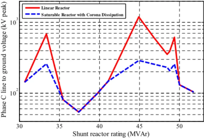
Figure 4 shows the resulted resonance voltage of phase C in no-fault condition versus the three phase shunt reactor ratings from simulations with linear and non- linear reactors. The voltage levels have dropped very much due to the saturation and corona losses.
30 35 40 45 50
102 103
Shunt reactor rating (MVAr)
Phase C line to ground voltage (kV peak)
Linear Reactor
S aturable Reactor with Corona Dissipation
Figure 4
The opened line phase C line to ground peak voltage versus three phase shunt reactor ratings: linear reactor and non-linear with corona loss simulation results, the bottom line is opened and the other ones
are energized. The upside diagram is Flux versus primary current of the saturable transformer.
2.4 Electrostatic No-Loss Analysis
In multi-conductor system, a capacitance matrix can be defined. First, the potential coefficient matrix (P) should be declared. It can be easily calculated based on the radiuses of conductors and the spaces between them [8, 25, and 26].
V PQ (2) In this stage, the effect of ground can be participated with electromagnetic mirror rule. By reversing the potential coefficient matrix the capacitance matrix is derived.
, 1
QCV C P (3) In a n-conductor system, the capacitance matrix would be in the order of n. If the order reduces to six, which is the number of line conductors (without guard wire), the capacitance matrix can be separated into four parts, as in (4) and after that the potential of the opened line conductors can be derived from the potential matrix of energized line conductors, regardless of the currents [8, 12, 27, and 28].
I I I I II I
II II I II II II
i C C e
i j C C e
eII CII II 1 YII II 1
CII I
eIj
(4)
iI = current matrix of the energized line iII = current matrix of the opened line eI = potential matrix of the energized line eII = potential matrix of the opened line
YII-II = the admittance matrix of the reactors connected to the opened line
ω = 2*pi*frequency
Without loss consideration, the opened line potentials go to infinity when the resonance occurs and it happens when the determinant of the first matrix becomes zero. So the equation that gives the resonant points is:
det( CII II 1 YII II ) 0 j
(5) In a six-conductor system like a double-circuit transmission line without a guard wire, the capacitance matrix can be separated into four 3*3 matrixes and then the resonance points can be calculated. In a double circuit transmission line with guard wires, the order of capacitance matrix is above 6 and for using this method we should decrease the matrix to the order of 6. We can use the principles of the capacitance matrix to reduce the order of the matrix.
In a capacitance matrix, the non-diagonal elements are the minus of the capacitors between corresponding conductors (6). The diagonal elements are the sum of the capacitors related to a conductor including the capacitance of that matrix to ground (7).
ij ij;
C c i j (6) Cij = non-diagonal element of the capacitance matrix
cij = capacitor between conductor i and j.
ii ig ij i j
C c c
(7) Cii = diagonal element of the capacitance matrixcig = capacitor between conductor i and ground cij = capacitor between conductor i and j.
So in a multi-conductor system with given capacitors, the capacitance matrix can be calculated using (6) and (7). In a system with a guard wire, regardless of the guard resistor, the wire has the potential of ground. This approximation is good especially in this case which we deal with low frequencies. So like the six- conductor system, we have seven potential references: six conductors of double- circuit and ground. For decreasing the order of the matrix, we should add the capacitors between each conductor and guard wire to the corresponding diagonal element because this capacitor is between a conductor and a guard wire having ground potential. After decreasing the order of the matrix, it can be separated and resonance points can be derived.
This method also can be used in fault conditions [13]. For example, when we have a line to ground fault on a conductor of the opened line, the potential of that conductor would be ground and we would have six potential points besides seven ones. We can add the capacitors between other conductors and the faulty one to the diagonal elements and then the matrix can be separated into four parts. In this case we have two unknown potentials on the opened line, so the CII-II would be 2*2 and therefore we have two resonant points in this case.
When we have a line to line fault, we have again six potential points because the potentials of two conductors, which are faulty, would be the same. The equivalent element of these two conductors in the capacitance matrix would be the sum of diagonal corresponding elements minus two times of the capacitor between them [13]. In this case, the admittance matrix would be different because one phase of reactor is on the conductor of the opened line which is not faulty and two parallel phases of the reactor are on the two conductors having a fault.
As a numerical example, the CII-II matrix is given in (8) when the bottom line is opened and the top ones are live. By solving the (5) for this matrix, the resonant points will be 5.4, 3.7 and 3.3 H corresponding to 30.8, 45 and 50.5 MVAr in 230 kV. The other resonance points for fault conditions can be calculated respectively by this method.
2.451 0.401 0.173 0.401 2.512 0.417 ( ) 0.173 0.417 2.642
II II
C f
(8)
3 Methods of Damping the Resonance Condition
Several possible routine avenues are possible for correcting the resonance situation. Assuming the reactor rating, reactive capability, stability, and light load or open circuit voltage limitations, the following alternatives are present [8]:
1) Complete transposition of the circuits.
2) Ungrounding the neutral of the reactor.
3) Insertion of a resistor between ground and neutral of the reactor.
4) Insertion of a reactor (either directly connected or coupled via a transformer) between ground and neutral of the reactor.
The solution works if it decreases the resonance voltages over reactor terminals in no-fault and faulty situations in three configurations: the bottom line is open and the top ones are live, the bottom line is open and one of the top lines is live, the bottom line is live and one or both of the top lines are open.
The first alternative may not be economically justified, especially when the circuit is constructed like here. The last three alternatives require analysis not only to ascertain the effectiveness of reducing the line-to-ground voltages, but since reactors have graded insulation, to determine that the neutral-to-ground voltage on the reactor is within the insulation specifications.
Ungrounding the neutral of reactor does not have any considerable effect.
Moreover, because of low neutral current in resonance situation, adding a resistor or a reactor in the neutral of the reactors does not help much and the reactor terminal voltages are still higher than the rated ones. Therefore, none of these routine solutions work in present circuit and new ways should be found to reduce the resonance voltages.
A possible way that is routine but has considerable cost is to add three 25 MVAr reactors in the system; one in Zahedan-Iranshahr line in Zahedan substation and the others in Khash substation, on Khash-Iranshahr and Zahedan-Khash lines as shown in Figure 5 (a). In this situation the bottom line will have overall 75 MVAr reactive compensation and each top line will have a 50 MVAr compensation; so the circuit will go far from resonance situation. In addition, when two lines are live, the compensation in Zahedan and Iranshahr substation will be 50 and 75 MVAr respectively and the voltage does not reduce too much because of high shunt compensation. The reason of choosing 25 MVAr reactors is that this type of reactors is routine and available in the Zahedan power section. Lower reactor ratings like 10 MVAr reactors can be added instead of 25 MVAr reactors, but this needs to build and design new reactors and so that buying three 35 MVAr reactors and replacing with the present ones will have the better reliability for system and the 25 MVAr reactors can be used in other places, so it is more beneficial.
Another way which has lower cost is replacing the ground disconnector switches with breakers. In this way, when one line is opened, the breakers can be closed and earth the system. Earthing with disconnector switches can be dangerous because high voltage induction on the line can cause arcing between switch terminals. This solution has a disadvantage. In the time between opening the line breakers and closing the earth breakers the reactors will withstand the temporary over voltages and this can damage them, but if this time decreases this overvoltage will be eliminated and the reactors will not be stressed out. Another disadvantage is that in this method the reactor windings suddenly become short circuited. If the windings have major voltages before the breaker closure it can damage the winding insulation due to the high voltage variation and non uniform voltage distribution over winding loops. Also the current that goes through the circuit breaker has a decay DC with large time constant and goes to zero in about 20 seconds, so the breaker must not open before this time because the current has no zero crossing. Adding a resistor in series with breaker can lower the time constant and the voltage variation stress on reactor windings.
Another way, which doesn't need any new equipment, is to change the reactor configuration in a way that no resonance happens. Figure 5 (b) shows the new proposed configuration. In this configuration, the Zahedan-Iranshahr line has 75 MVAr shunt compensation and has no strict resonance in open condition. The top lines have no shunt compensation in dead condition and have no resonance as well. Moreover, when the top line is connected, it has a 25 MVAr reactive compensation and the reactor is located in the middle of the line, so the overvoltage of half of the top line is not so high. Substations have also other lines with reactive compensation and there isn't a severe overvoltage in the light load situation. Figure 6 shows the voltage on the bottom line when it opens at 1.5 s and the top lines are connected.
Another strategy is using a TCR configuration with resistor instead of an indicator for damping the resonance condition. The proposed layout is shown in Figure 7 (a). When the line to ground voltage of a line becomes higher than 1.2 pu, then a controller can increase the duty cycle of switching and intensify the effective resistor resulted in the decrease of resonance voltage. A wide range of resistors will lower the resonance voltage below the rated terminal level. As an example in the presented circuit, a 270 Ω resistor can reduce the resonance induction below the nominal voltage of rector terminals and the corresponding power loss is about120 kW. By using the substation internal feeding transformer type as the TCR transformer, it doesn't need to design and buy a special transformer and the cost will decrease. These types of transformers have the rated 300 kVA nominal power so are suitable for this application. These transformers have the ratio of 230 kV/400 V, so there isn't any need to high voltage thyristors and the high current low voltage ones, which are very usual, can fit into this structure. The main disadvantage of this solution and the ones which need adding equipments are lowering the system reliability.
Figure 5
The new configuration proposed for lowering resonance voltage levels: (a) by adding new reactors, (b) using the available reactors
1 1.5 2 2.5 3 3.5 4
-200 -150 -100 -50 0 50 100 150 200
Time (s)
Phase voltage (kV)
Figure 6
Damping of resonance in phase C with re-configuration
Another possible approach is to insert a transformer like the previous solution but connecting a capacitor bank in the secondary of the transformer. In this way the voltage level will decrease very much, if a suitable capacitor is chosen. The considerations in this solution are the capacitor bank current, switching the transformer and ferroresonance of the transformer and the capacitor. The voltage reduces due to equivalent capacitor seen by the system but there is a current which is related to residual voltage on the system. If the capacitor selection will be correct the residual voltage will be very low and the current of capacitor bank will be limited. In this case, insertion of a 3 MVAr capacitor bank in the secondary of a 230 kV/ 20 kV transformer just in one side of the bottom line will decrease the all reactor terminal line to ground voltages to 15 kV peak from 240 kV peak in the absence of the capacitor bank and the steady state current of capacitor bank will be 110 A RMS in the worst phase. The switching of capacitor bank always has some transients, but in this situation switching is done through the transformer and the equivalent inductor of transformer limits the transient overcurrent. In the presented case, using a regular transformer with 0.1 pu series impedance, the first peak during switching becomes 55 A when the steady state current of the primary of the transformer is 10 A RMS. The last consideration is ferroresonance of the
transformer with the capacitor bank. When the transformer is connected to the system, the ferroresonance happens but the voltage peaks aren't too high and by adding a resistor in series with the capacitor banks, this ferroresonance will damp.
Therefore, there is no strict stress over transformer and the capacitor bank. In this case, a 1 Ω resistor in each phase will damp the ferroresonance in about 5 seconds and the power loss of each of them during connection to the circuit is about 12 kW. In this procedure, the reactor will be stressed out during the time between the opening of the line breaker and the connection of the capacitor bank. Figure 7 (b) shows the detail of the configuration of this solution. Figure 8 shows the voltage on the bottom line when this solution has been applied. In this figure the top lines are energized and the bottom line opens at 1.5 s, then, the capacitor bank connects at 5 s. It is obvious that there is a slight ferroresonance but it damps within 2 s and the steady state voltage of line is lower than the re-configuration method.
Figure 7
Proposed configurations for damping the resonance circuit: (a) using a switching resistor, (b) using a capacitor bank
1 2 3 4 5 6 7 8 9 10
-400 -300 -200 -100 0 100 200 300 400
Time (s)
Phase voltage (kV)
Figure 8
Damping of resonance in phase C with capacitor bank
Among all above approaches, changing the configuration of reactors (Figure 5 (b)) is the best solution, because it doesn't need any additional equipment and it is cheaper than others. Also the reliability of the final system will be the best compared to the other solutions.
Conclusions
1. Choosing the reactors rating in a double circuit transmission line needs special considerations of parallel resonance probability.
2. For finding the resonance points, all available configurations of the line including various faults on the energized and opened line should be considered.
3. Faults on the opened line leads to different resonant points, but faults on the live circuit changes the resonance voltage levels.
4. The electrostatic no-loss solution gives good estimation about the resonance points and can be used for selecting the appropriate shunt reactive compensation.
5. Modeling the system in PSCAD using Bergeron transmission line model without damping approximation leads to answers which are favorably comparable to the ones from electrostatic method and can be used for reactors rating selection. As well, Reactor saturation and corona losses can be modeled to get better results.
6. In resonance situations which the neutral of reactor current is low, insertion of reactor or resistor in the neutral of the reactors does not have considerable effect on the voltage levels.
7. The TCR configuration with appropriate resistors can be used to lower the resonance voltage.
8. Insertion of suitable capacitor can highly affect the resonance condition and can be used for damping the resonance circuit, but needs special considerations.
9. In resonance condition the opened line can be earthed by using circuit breakers instead of the earth disconnector switches.
References
[1] G. XinBo, W. YingShi, Q. Tong, X. Wei, L. Daoning: The Simulation of the Controllable Reactor and It's Application in Ultra High Voltage Transmission Lines, Int. Conf. Advanced Power System Automation and Protection, TBEA Shenyang, China, 2011, Vol. 3, pp. 1833-1837
[2] R. Begamudre: Extra High Voltage AC Transmission Engineering, New Age International, 2007
[3] Z. Li, X. Yuqing: Application and Development of Shunt Reactors in EHV
& UHV Transmission Lines, Electric Power Automation Equipment, 2007, vol. 21(4), pp. 18-24
[4] X. Qiufeng, W. Haiyan, W. Zhiwei: Application and Development of Shunt Reactors in EHV & UHV Transmission Lines,Guangdong Power Transmission Technology, 2007, Vol. 24(4), pp. 4-6
[5] P. Zhendong, Z. Jiawen: Power Frequency Over-Voltage of 500 kV Four- Circuit Lines on the Same Power, East china electric power, 2007, Vol.
35(3), pp. 24-27
[6] G. Dingxie, Z. Peihong: Over-voltage, Secondary Arc and Reactive Power Compensation in UHV AC Transmission System, High Voltage Engineering, 2005
[7] C. Hansheng, H. Danhui, T. Caiqi: Study on the Shunt Comensation and Overvoltage in Zhengnan 500 kV System, High voltage engineering, 2000, Vol. 26(5), pp. 34-37
[8] M. Hesse, D. Wilson: Near Resonant Coupling on EHV Circuits: II - Methods of Analysis, IEEE Trans. Power Apparatus and Systems, vol.
PAS-87, Feb. 1968, No. 2, pp. 326-334
[9] X. Lv, Q. Sun, Q. Li, W. Shi: Multi-objective Parameter Optimization of Shunt Reactors for Multi-circuit Transmission Lines on the Same Tower, in Proc. 4th Int. Conf. Electric Utility Deregulation and Restructuring and Power Technologies (DRPT), 2011, pp. 271-276
[10] M. Pickett, H. Manning, H. Van Geem: Near Resonant Coupling on EHV Circuits: I – Field Investigations, IEEE Trans. Power Apparatus and Systems, Vol. PAS-87, Feb. 1968, No. 2, pp. 322-325
[11] A. Chaston: EHV AC Parallel Transmission Line Calculations with Application to the Near Resonance Problem, IEEE Trans. Power Apparatus and Systems, May. 1969, Vol. PAS-88, No. 5, pp. 627-635
[12] K. Priest, A. Ramirez, H. Howak, J. Laforest: Resonant Voltages on Reactor Compensated Extra-High-Voltage Lines, IEEE Trans. Power Apparatus and Systems, Nov. 1972, Vol. PAS-91, No. 6, pp. 2528-2536 [13] E. E. Colapret, W. E. Reid.: Effects of Faults and Shunt Reactor Parameters
on Parallel Resonance, IEEE Trans. Power Apparatus and Systems, Feb.
1981, Vol. PAS-100, No. 2, pp. 572-584
[14] W. E. Reid, R. F. Gustin, P. V. Zylstra: Guidelines for Determining Parallel Resonance on EHV Transmission Lines, IEEE Trans. Power Apparatus and Systems, Sep. 1983, Vol. PAS-102, No. 9, pp. 3196-3204
[15] M. H. Hesse, J. Sabath: EHV Double-Circuit Untransposed Transmission Line-Analysis and Tests, IEEE Trans. Power Apparatus and Systems, May 1971, Vol. PAS-90, No. 3, pp. 984-992
[16] M. V. Escudero, M. Redfern: Parametric Analysis of Parallel Resonance on Shunt Compensated Transmission Lines, in Proc. 39th Int. Conf.
Universities Power Engineering, UPEC, 2004, Vol. 2, pp. 1181-1185 [17] L. Wei, N. Wen-hui, H. Dong-shan: Analysis and Modification of a 500kV
Transmission Line Overvoltage Problem, in Proc. 2010 China Int. Conf.
Electricity Distribution (CICED), pp. 1-6
[18] A. B. Fernandes, W. L. A. E. Neves, G. Costa, M. N. Cavalcanti: The Effect of the Shunt Conductance on Transmission Line Models, in Proc.
Int. Conf. Power System Transients, Rio de Janeiro, Brazil, 2001, pp. 49-54 [19] PSCAD Online Help, v4.2.1, Manitoba HVDC Research Centre Inc., 2006 [20] H. W. Dommel: Digital Computer Solution of Electromagnetic Transients
in Single and Multiphase Networks, IEEE Trans. Power Apparatus and Systems, Vol. PAS-88, No. 4, pp. 388-399, Apr. 1969
[21] A. R. Hileman: Insulation Coordination for Power Systems, Boca Raton:
CRC-Taylor & Fransis Group, 1999, ch. 9
[22] J. A. Martinez-Velasco: Power System Transients Parameter Determination, Boca Raton: CRC-Taylor & Fransis Group, 2010, ch. 2 [23] J. C. Das: Transients in Electrical Systems Analysis, Recognition, and
Mitigation, McGraw-Hill, 2010, ch. 4
[24] F. W. Peek: Dielectric Phenomena in High Voltage Engineering, McGraw- Hill, 1915, ch. 5
[25] D. K. Cheng: Field and Wave Electromagnetics, Addison-Wesley, 2nd edition, 1989, ch. 3
[26] H. Saadat: Power System Analysis, McGraw-Hill, 1999, ch. 4
[27] E. T. B. Gross: Unbalances of Untransposed Overhead Lines, J. Franklin Inst., 1952, Vol. 254, pp. 487-497
[28] E. T. B. Gross, M. H. Hesse: Electromagnetic Unbalance of Untransposed Transmission Lines, Trans. AIEE (Power Apparatus and Systems), Dec.
1953, Vol. 72, pp. 1323-1336