CHAPTER 4
Flow Patterns, Fluid Velocities, and Mixing in Agitated Vessels
Joseph B. Gray Ε. I. du Pont de Nemours and Company, Inc.,
Wilmington, Delaware
I. Introduction 179 II. Relationships between Flow Patterns, Fluid Velocities, Flow
Rates, and Mixing 180 III. Impeller Discharge Rates 180
A. Theoretical Relationships 180 B. Experimental, Impeller Discharge Rates 187
C. Comments on Impeller Discharge Data 206
IV. Batch Mixing in Agitated Vessels 208 A. Correlation of Mixing Times and Impeller Discharge Rates 209
B. Turbine and Propeller Mixing 211 C. Side-Entering, Propeller Mixing 225
D . Jet Mixing in Vessels 239 E. Scale-Up of Batch Mixing Performance 245
F. Comments on Batch Mixing 247 V. Continuous Mixing in Agitated Vessels 248
A. Effect of Flow Pattern on Continuous Mixing 248
B. Applications of Continuous Mixing 250 C. Theoretical Continuous Mixing Relationships 251
D . Experimental Continuous Mixing Data 254 E. Comments on Continuous Mixing 274
List of Symbols 275 References 277
I. Introduction
W h a t takes place in a moving fluid when concentration or property differ- ences are present has been described in C h a p t e r 2. There, mixing is considered t o be a process in which progressively greater uniformity is obtained as a result of various types of fluid m o t i o n such as laminar flow, turbulent flow, a n d molecular diffusion.
I n this chapter, simplified m e t h o d s are used t o describe w h a t takes place in vessels in which fluid m o t i o n t h a t is induced by moving propellers, turbines, or j e t s of fluid is used to p r o m o t e mixing. T h e relationships of fluid velocities,
179
180 Joseph B. Gray
flow rates, a n d flow patterns in vessels to the mixing process are discussed.
Correlations are presented for predicting the flow produced by impellers and the time to obtain an arbitrary uniformity in batch mixing operations.
Methods are presented for predicting the effects of mixing in an agitated vessel on changes in concentration or properties in a continuous stream of fluid entering a n d leaving the agitated vessel.
II. Relationships between Flow Patterns, Fluid Velocities, Flow Rates, and Mixing
T h e forces applied by an agitator moving in a fluid contained in a vessel maintain a flow pattern in the fluid. If the flow pattern is laminar, the direc- tions and magnitudes of velocities at each point in the vessel are constant or there is a regular periodic variation. If the flow pattern is turbulent, there is an average direction and magnitude of velocity at each point and a r a n d o m variation in these values with time due to turbulent velocity fluctuations.
These movements interchange fluid between different parts of the vessel.
If fluid properties are not the same at these different locations, this interchange of fluid reduces the difference in the properties. Such a process makes macro- samples of the fluid more uniform in properties or composition.
When fluid with varying properties is fed continuously to an agitated vessel, the magnitude of these variations is lower in the effluent stream than in the entering stream. When a small quantity of fluid is added in a short time to an agitated vessel already filled with another fluid, an initial difference in com- position or properties will be reduced.
These continuous and batch mixing operations are influenced by the flow rates, velocities, a n d flow patterns of the fluid within an agitated vessel.
Higher velocities provide faster reduction of concentration or property differences. Some flow patterns are better suited than others for distributing fluid added to the vessel throughout all parts of the vessel. If velocities are relatively low in a region of the vessel, a n d fluid does n o t enter and leave readily, that region is relatively stagnant and the flow pattern is unsuited to mixing uniformly and rapidly throughout the vessel.
III. Impeller Discharge Rates A . THEORETICAL RELATIONSHIPS
The relationships between impeller geometry, rotational speed, and other variables have been studied in detail for centrifugal pumps (S3, W3). The basic principles which relate head developed, fluid velocities, flow rates, power consumption, a n d equipment geometry are applicable also t o rotating impellers in agitated vessels. In this section are described the theoretical and empirical relationships which have been obtained by various investigators
4. Mixing in Agitated Vessels 181
= v2c + vî - 2vpvc COS OL (i) vl = v2r + (œr-kœr)2 (2)
vr = vw sin β (3)
Vc COS OL = kœr (4)
vr = sin β\/(kœr)2 tan α + (œr — kœr)2 (5)
VP = œr (6)
where
vc = fluid velocity leaving the periphery of an impeller, ft./min., k = ratio of tangential fluid velocity at the periphery of an impeller to the
peripheral impeller velocity,
r = radial distance from center of rotation, ft., vp = peripheral impeller velocity, ft./min.,
between discharge velocities and flow rates, impeller geometry and rotational speed.
1. Curved-Blade Turbines
In Fig. 1 are shown the velocity vectors at the periphery of a curved-blade turbine impeller. The following equations can be written from inspection of this diagram:
β / \
y\
ι \
VcΧ ι \
/ \ χ ^\
ν
i \ΧΥ
Ι Α Λ/ L \
1 ι
\ /
\ /
\ /
\ /
\ ^ ^ /
FIG. 1. Discharge velocity for a curved-blade turbine.
182 Joseph B. Gray vr = radial velocity component, ft./min.,
vw = fluid velocity relative to impeller blade tip, ft./min., ol = angle between velocity vectors, vc and vp9
β — angle between impeller tip and velocity vector, vp9
ω = angular velocity, radians/min.
A n equation relating velocities a n d theoretical head developed by a rotating impeller can be derived from an angular m o m e n t u m balance. The time rate of change of angular m o m e n t u m of the fluid passing through the impeller is equal to the torque, Tf, or m o m e n t of the forces applied to the fluid by the impeller surfaces,
Tf = QPœkr*/gc (7)
where
gc = gravitational conversion factor, 115,900 (lb./lb^) (ft./min.2), Q = impeller discharge rate, cu. ft./min.,
ρ = fluid density, lb./(cu. ft.).
In writing this equation, the angular m o m e n t u m of fluid entering the impeller was assumed to be zero. If both sides of Eq. (7) are multiplied by the impeller rotational speed, ω , the following relationship is obtained.
7 > = QPkœ*r*lgc (8)
The left side of this equation is the power consumption, P, of the agitator. If fluid friction losses are assumed to be zero, this power can also be expressed as follows :
Ρ = QpH (9) where Η = theoretical impeller head, ft.
F r o m Eqs. (8) a n d (9),
H = kœ2r2/gc (10)
This theoretical head, H, appears at the impeller periphery as kinetic and static heads if there are no friction losses in the impeller. The kinetic head is v2J2gc
and the static head is that due to centrifugal force on the liquid at the impeller periphery, (kwr)2/2gc. Therefore,
H = v\l2gc + (kœry/2gc (11)
and
ko?r2\gc = v2J2gc + (kœryi2gc (12) When vw, ve, and cos α are eliminated from Eqs. (1), (2), (4), (6), and (12), the
following relationship is obtained :
vr = wr^2k{\-k) (13)
4. Mixing in Agitated Vessels 183
Q = n2bND2^2k(\-k) (21)
or
NQ = n2(b/D)j2k(l-k) (22)
where
NQ = QjND* (23)
Similarly, from Eq. (16),
NQ = w%b/D) sin β^Ι-k2 (24)
F r o m Eqs. (9), (10), and (19) a simple relationship between power consump- tion, flow from an impeller, and the ratio of tangential fluid velocity to impeller peripheral speed can be derived :
Ρ = 7T2QpkN2D2/gc (25)
A relationship between k and OL can be obtained from Eqs. (4) and (12) by elimination of vc.
t a n2 a = 2(1-k)/k (14)
T h a t angle β is also a function of k can be shown by eliminating vr and vw
from E q s . (2), (3), and (13).
t a n2 β = 2kl(\-k) (15) Therefore k, a, and β are not independent. If t a n2 α from Eq. (14) is sub-
stituted in Eq. (5), Eq. (16) is obtained:
vr = corsin
j S V f ^
(16)This is the equation given by Van de Vusse (VI) for a curved-blade turbine.
The radial pumping capacity of an impeller in an agitated vessel is cal- culated from the following equation :
Q = 2iTbrvr (17)
where b = axial impeller blade width, ft.
Then, by substitution of vr from Eq. (13),
Q = 2nb<or2J2k(l-k) (18)
Since
ω = 2πΝ (19) a n d
r = D/2 (20) where
Ν = agitator rotational speed, r.p.m., D = agitator diameter, ft.
Then,
184 Joseph B. Gray
If each side of this equation is divided by n2kpN3D5 the following relationship is obtained after rearranging terms :
QjND3 = gcP/(^kPN*D*) (26)
or
NQ = Nplv*k (27)
where
Np = gcPipN*D5 (28)
Equation (27) was derived from relationships that are independent of the type of impeller. However, zero friction losses were assumed for fluid passing through an impeller and the fluid entering the impeller was assumed to be not rotating.
Equations (22) and (24) require modification for application to impellers in agitated vessels because (a) the flow from actual impellers is distorted by the use of relatively few blades or vanes, (b) part of the kinetic and static heads is dissipated by turbulent motion and viscous drag, and (c) the fluid does not have zero rotational velocity entering the impeller as assumed in Eqs. (7), (8), (10), and (11) unless the vessel is baffled. The use of baffles at the vessel walls will affect the extent of turbulent and viscous drag. The values of k will approach 1 when no baffles are used, and k will become smaller when baffles are present. In some cases, k may be as small as 0.1 according to estimates of k from Eq. (27) and NPINQ from Tables I and IV.
The following two basic principles were used to obtain a relationship between impeller rotational speed and radial flow rate of fluid:
(a) The rate of change of angular m o m e n t u m of the fluid passing through an impeller is equal to the torque required to rotate the impeller.
(b) The theoretical fluid head induced by the impeller is equal to the static head plus the kinetic head of the fluid at the exit of the impeller.
These same principles apply to impellers with pitched blades and they have been applied to obtain relationships between torque, thrust, and rotational speeds for propellers and other axial flow impellers (W3). However, these relationships do not appear in any agitation references.
2. Pitched-Blade Turbines
Van de Vusse (VI) describes a method of estimating the discharge velocity and flow rate from an impeller with inclined blades. A single blade and the velocity vectors in a plane tangent to the circular path of the tip of this blade are illustrated in Fig. 2. In this figure, vp is the peripheral blade velocity, ω/·, and y is the angle of pitch of the blade face. The absolute velocity of the liquid is vL. The difference (vp — vL)\s the velocity of the liquid relative to the blade.
Velocity components of the fluid approaching the blade which are in an axial
4 . Mixing in Agitated Vessels 1 8 5
Impeller
Symbol0 Descripton DjT b\D NP NPINQ NSex ΙΟ- a 16-Flat-blade turbine 0.513 0.20 1.08 0.33 3.3 Ι b 16-Flat-blade turbine 0.513 0.20 1.06 0.33 3.2 1
Ci 8-Flat-blade turbine 0.513 0.10 0.81 0.25 3.2 1 c2 8-Flat-blade turbine 0.513 0.20 0.95 0.34 2.8 1
Cz 8-Flat-blade turbine 0.513 0.30 1.04 0.47 2.2 1
Ci 8-Flat-blade turbine 0.513 0.40 1.07 0.59 1.8 1 di 8-Curved-blade turbine 0.513 0.20 0.88 0.43 2 1 d2 8-Curved-blade turbine 0.513 0.20 0.71 0.43 1.7 1 dt 8-Curved-blade turbine 0.513 0.20 0.55 0.37 1.5 1 d* 8-Curved-blade turbine 0.513 0.20 1.06 0.27 3.9 1 ei 8-Flat-blade turbine
(f of corners cut off)
0.513 0.20 0.84 0.24 3.5 1
e* of corners cut off) 0.513 0.40 1.05 0.51 2.1 1 ( J of corners cut off) 0.513 0.40 1.04 0.46 2.3 1 ei 8-Flat-blade turbine
C| of corners cut off)
0.513 0.40 0.99 0.46 2.2 1
I (Corners widened) 0.513 0.20 1.09 0.46 2.4 1 f Raised blade turbine 0.513 0.20 0.94 0.28 3.4 1 g 8-Blade arrowhead turbine 0.513 0.20 0.95 0.26 3.7 1 h 3-Flat-blade turbine
(similar to cx) 0.489 0.10 0.60 0.19 3.2 1 i Pfaudler-type impeller 0.489 0.10 0.37 0.23 1.6 1 j 8-Blade, pitched-vane-type
impeller 0.513 0.20 0.44 0.34 1.3 1 8-Pitched-blade turbine ( y = 90°) 0.513 0.20 0.95 0.34 2.8 1 k2 8-Pitched-blade turbine ( y = 60°) 0.513 0.17 0.84 0.36 2.3 1 k, 8-Pitched-blade turbine ( y = 45°) 0.513 0.14 0.72 0.31 2.3 1 k* 8-Pitched-blade turbine ( y = 30°) 0.513 0.10 0.51 0.30 1.7 1 Pi 8-Flat-blade turbine 0.308 0.33 2.17 1.23 1.8 0.37
o2 8-Flat-blade turbine0 0.718 0.14 0.57 0.144 4 2 1 Rotating disk 0.513 — 0.045 0.031 1.45 2.1
a From Nagata et al (NI).
b See Fig. 7.
c Similar to c2 but D = 42 cm.
or radial direction are neglected or assumed to be zero. T h e fluid is assumed to leave the blade in a direction parallel to the face of the blade. T h e magni- tude of this velocity in a plane which is perpendicular to the plane of the blade and parallel to the axis of rotation of the blade is equal to (vp — vL) cos γ. T h e vertical c o m p o n e n t of this velocity relative to the blade is (vp — vL) sin γ cos γ a n d the tangential c o m p o n e n t is (vp — vL) c o s2 y. T h e velocity of the latter relative t o the liquid a p p r o a c h i n g the blade is vp — (vp — vL) c o s2 γ — νL which
TABLE I
Discharge Performance of Impellers in an Unbaffled Vessel*
186 Joseph Β . Gray
FIG. 2. Discharge velocity for a pitched-blade turbine (radial view of blade).
is equal to (vp — vL) sin2 y. The radial velocity of fluid leaving the inclined blade was assumed by Van de Vusse to be equal to the tangential velocity of fluid leaving the blade minus the tangential velocity of fluid entering. This radial velocity is (vp — vL) sin2 y. N o experimental basis for this assumption was presented by Van de Vusse.
If all fluid leaving the impeller has an axial velocity equal to (vp — vL) cos y sin y or (ω — œL)r cos y sin y where œLr = vL, then the axial flow rate is
r
ôaxiai = / (ω - *»ΰ cos y sin γ 2nndr (29) ο
Ôaxiai = (ω - ( π / 1 2 ) / )3 sin y cos y (30) The radial discharge flow rate is
ôradiai = Op ~ H) (sin2 y)b*D (31)
ôradial = (Φ) (ω " « J (sin2 y ) è £2 (32) Since
Q = Ôaxiai + ôradial (33) where g is the total flow rate,
QjND3 = (1 - £ ) π2 [(1/6) sin y cos y + (b/D) sin2y] (34) This equation was modified by Van de Vusse for use in correlations of mixing time [see Eq. (62)].
5. Propellers
Van de Vusse (VI) derived a flow equation for a marine propeller in a similar way. In this case, the angle, y, is a function of the radial distance from the axis of rotation.
tan y = p/2nr (35)
4. Mixing in Agitated Vessels 187 where ρ is the propeller pitch. Pitch is related to sin γ and cos γ as follows :
sin γ = PKP2 + 4 π2Γ2) * (36)
cos γ = 2nr/(p2 + 4ΤΓ2α·2)* (37)
When these expressions for sin γ and cos γ are substituted in Eq. (29), the axial flow rate is
r
ôaxial = 4π*(ω - oL)p J"[r»/(p« + 4*V)]<fr (38)
0
Ôaxia. = l/8(« - « L) ( / > / £ ) £3 [1 - (p2l"2D*)ln (1 + T T ^ /p2) ] (39) If pi D = 1 a n d o jL = 0,
QvJNB* = 0.60 (40) If a propeller displaced fluid for a distance equal to its pitch per revolution
with no slip, the volumetric discharge rate, Q, would be
Q = (n/4)D2pN (41)
Brothman et al. (B3) recommended using 0*6 of this flow rate. Then for ρ = d,
QjND3 = 0.47 (42)
which is smaller than the value of 0.60 obtained from Eq. (39) when pjD = 1 and c uL = 0.
B. EXPERIMENTAL, IMPELLER DISCHARGE RATES 1. Discharge Rates From Velocity Data
N a g a t a et al. ( N I , N 2 , N3) have studied velocities, flow rates, and flow patterns extensively for rotating impellers. D a t a were reported for 30 different impellers in baffled and unbaffled vessels for Reynolds numbers from 10 to 105. In all cases, the impellers were located halfway between the liquid surface and the b o t t o m of the vessel. A 23-in. diam. vessel was used for the baffled and unbaffled tests at high Reynolds number (approximately 105).
F o r water velocity measurements at high Reynolds number, two types of velocity measuring tubes were used. The direction of flow was measured by two parallel, adjacent, 2-mm. diam. tubes connected to a manometer. When the direction of the tubes and the flow of liquid were the same, there was no difference in the manometer fluid levels. Velocity measurements were made by a single 5-mm. o.d. Pitot tube oriented in the direction indicated by the zero manometer reading for the parallel tubes.
F o r measurements at intermediate and low Reynolds numbers, a p h o t o - graphic method was used in which a plane beam of light was projected through various sections of an 11.8-in. diam. vessel. This method is similar to that used by Sachs and R u s h t o n (SI). Fine particles, such as naphthalene powder
188 Joseph B. Gray
suspended in the liquid, reflected the light. Photographs were taken of the trajectories of the gleaming particles a n d were used to calculate directions and velocities of the liquid in which the particles were suspended.
Pitot tube and photographic d a t a were obtained only for the upper half of the vessel. The velocities in the lower half of the vessel were assumed to be similar to those in the upper half.
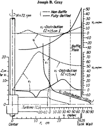
Typical velocity data are shown in Figs. 3 , 4 , a n d 5 . As expected for a n
Vt, cm/sec.
29.25
FIG. 3. Tangential velocities produced by turbine (a) in an unbaffled vessel at 72 r.p.m.
Turbine is located halfway between the water surface and the bottom of the vessel (Nl).
unbaffled vessel, tangential-velocity components are high relative t o radial and axial components. T h r o u g h o u t the region above and below the rotating impeller, the tangential-velocity component is proportional to the distance from the center of the agitator shaft as shown in Fig. 3 . Radial velocity components are toward the vessel wall in the region between the upper a n d lower edges of the impeller and are toward the agitator shaft in all other regions as shown in Fig. 4 . The axial velocity component plot, Fig. 5 , shows that fluid moves away from the impeller at the vessel wall and in part of the region above the impeller. The fluid returns to the impeller in the annulus between the dotted lines shown in Fig. 5 . and in the annulus adjacent to the agitator shaft. N o explanation is offered by N a g a t a for the upward flow in part of the zone above the impeller.
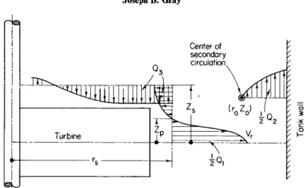
The combined radial and axial flow produced by each impeller was cal- culated from velocity data by integration of the velocity data at the locations in the vessel shown in Fig. 6. The distances, Zs and rs, were arbitrarily selected
4. Mixing in Agitated Vessels 189
V , cm./sec.
r29.25
8 12 16 20 26 29.25 r,cm.
FIG. 4. Radial velocities produced by turbine (a) in an unbaffled vessel at 72 r.p.m.
Turbine is located halfway between the water surface and the bottom of the vessel ( N l ) .
Ν =72 r.p.m.
Î6
1 ' « 2 50 1 0
r, cm
FIG. 5. Axial velocities produced by turbine (a) in an unbaffled vessel at 72 r.p.m.
Turbine is located halfway between the water surface and the bottom of the vessel (Nl).
190 Joseph B. Gray
FIG. 6. Reference points for calculating impeller discharge rates from velocities in unbaffled vessels (Nl).
to permit defining the discharge flow, Ql9 from the impeller as follows :
Qi = 4*rsj vrdZ (43)
The flow, g3, moving toward the impeller can be computed as follows :
Zs rs
Qs = 4*rs j vrdZ + 4 π j rvzdr (44)
zp 0
Since flow toward the impeller is equal to the flow away from the impeller, 0 3 = Qv
The flow, Q29 u p the vessel wall can be calculated from :
Q2 = 4njv2rdr (45)
The center of secondary circulation ( r0, Z0) is located from the experimental velocity d a t a ; ( r0, Z0) is the point where both radial and axial components of velocity are zero.
N a g a t a et al. expressed the flow rate, Ql9 in dimensionless form as follows:
NQ = QJNB* (46)
The Reynolds numbers and power numbers corresponding to each co- efficient of impeller discharge, NQ, are presented in Table I. The letters a, b, c, etc., identify the impellers pictured in Fig. 7.
N a g a t a et al. used the ratio NP/NQ as a measure of impeller discharge performance:
NPINQ = (gcPj pN3D5)l (QJN D3) = gcP/pN^Q, (47)
4. Mixing in Agitated Vessels 191
(α) 16 Flat-Blade (t>) 16 Flat-Blade (θ) 8 Flat-Blade (d) 8 Curved-Blade (β) 8 F lot-Β laded Turbine Turbine Turbine Turbine Turbine
Corners Cut Off
ι ι ι 1
(lj
7.5 cm.1- D -I ^22·5 cm-| Αβ- L 30 cm. -*j
D - 3 0 c m . D = 30cm. D = 30 cm. D - 30 cm. ( e , ) b/ K = 0.20 c/. = 1 / 3 b = 6 c m . b - 6 cm. ( C , ) b = 3 cm. (d, ) £,= 40° (,,)^ = 0 . 2 0C /b = 1/8
(C2) b = 6 cm. ( d2) ^ = 60° Mhfa = 0.20 c^ = 1/6 (C,) b = 9 cm. « , ) / ? ' = 80° (β 4) b/K = 0.20 CA = 1/4 ( C4) b = 12 cm. ( « 0/ 9 = -60°
Roised-Blode , . 8 Blade-Arrow Curved-Raised Pitched 8 Pitched-Blade 8 Flat-Bladed ( f ) Turbine W Head Turbine (l) Turbine (j ) Vane Type ( K ) Turbine (]) Turbine
Ϊ
Impel 1er Corners WidenedD = 30cm. D = 28.6 cm. ^ ™' on . D « 30 cm.
b = 6 c m . D = 30cm. b = 6 cm. b= 3 cm. D = 30 cm. b « 6 cm.
b = 6 c m . ( k , ) y » 90° (k,) y = 45°
( k2) y = 60° (k4) y = 30°
FIG. 7. Impellers used by Nagata et al. (NI, N2, N3).
192 Joseph B. Gray
This ratio is proportional to the power per unit flow rate of fluid discharged by an impeller when pN2D2 is the same for all impellers. If HQp from Eq. (9) is substituted for Ρ in Eq. (47), a relationship is obtained between velocity head, H, and the ratio NPjNQ
NPINQ = gcHI(N2D2) (48)
The ratio, NPjNQ, is also proportional to the theoretical velocity head, H9
of fluid discharged by an impeller if ND or peripheral velocity is constant.
The experimentally measured discharge rates were widely different for the various impellers studied. The discharge rates for the data in Table I range from 0.069 to 0.43 ft.3/sec. Since turbulence will extend to a larger fraction of the vessel for an impeller which produces a high discharge rate than for an impeller which produces a low one, the flow conditions in the vessel can be different for two impellers at the same Reynolds number.
A n appropriate basis of comparison of impeller discharge performance is the power required for each impeller at the same discharge rate. The data in Table I were used to calculate the power needed for a 0.265 ft.3/sec. discharge rate. In Table II are shown the results of these calculations. Assuming that NP a n d NQ do not change with NRe was necessary in obtaining the values shown.
The following conclusions can be drawn on the basis of the data in Table II for an unbaffled vessel :
1. Using a disk to support impeller blades has no significant effect on the power required to obtain the same discharge rate (see a and b in Table II).
2. Increasing axial blade width, b9 markedly increases impeller discharge efficiency as measured by power to obtain the same discharge rate (see cl9 c29 c3, and c4) .
3. Curving the impeller blades increases discharge efficiency ( c2, dl9 d29 d3).
Curving the blades in the direction of rotation decreases efficiency (see i/4, and c2) .
4. Cutting off the corners of the blades at the periphery of the impeller decreases efficiency (compare e1 and c2).
5. Moving the tips of the blades axially relative to the impeller h u b decreases efficiency ( / a n d c2).
6. An " a r r o w h e a d " turbine is less efficient than a flat-bladed turbine (g and c2).
7. A pitched-vane impeller is more efficient than a turbine impeller (j and c2) 8. Increasing impeller diameter decreases discharge efficiency (pl9 c29 o2).
9. A rotating disk (q) has very poor discharge efficiency.
Further velocity data in unbaffled vessels were obtained by N a g a t a et al.
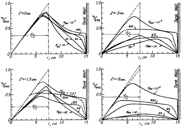
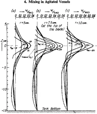
(N3) for Reynolds numbers from 10 to 105. The effect of changing Reynolds number on typical velocity data for impeller c2 is shown in Figs. 8 and 9 for tangential and radial velocity components. The tangential and radial velocities
4. Mixing in Agitated Vessels 193 TABLE II
Impeller Discharge Performance at the Same Discharge Ratea in an Unbaffled Vessel Impeller
Power
Symbol6 Description (ft.-lb./sec.)
a 16-Flat-blade turbine 1.15
b 16-Flat-blade turbine 1.13
Ci 8-Flat-blade turbine 1.98
8-Flat-blade turbine 0.93
8-Flat-blade turbine 0.38
c4 8-Flat-blade turbine 0.198
dx 8-Curved-blade turbine 0.42
d2 8-Curved-blade turbine 0.34
dt 8-Curved-blade turbine 0.42
d* 8-Curved-blade turbine 2.1
ex 8-Flat-blade turbine
(f of corners cut off) of corners cut off)
2.3 e%
(f of corners cut off)
of corners cut off) 0.31
e3 of corners cut off) 0.41
of corners cut off) 0.39
I (Corners widened) 0.43
f Raised blade turbine with 8 blades 1.65
g 8-Blade arrowhead turbine 2.1
h 8-Flat-blade turbine 3.8
i Curved raised-blade turbine (Pfaudler) 1.31
J 8-Blade, pitched-vane-type impeller 0.43
kx 8-Pitched-blade turbine (y = 90°) 0.93
k2 8-Pitched-blade turbine (y = 60°) 0.69
k3 8-Pitched-blade turbine (y = 45°) 0.93
k, 8-Pitched-blade turbine (y = 30°) 0.73
Px 8-Flat-blade turbine 0.34
o2 8-Flat-blade turbine 1.89
Q Rotating disk 58
a 0.265 ft.3/sec.
b See Fig. 7.
decrease considerably at locations remote from the impeller as Reynolds number decreases. A t low Reynolds numbers, the flow is laminar throughout the vessel ; at intermediate values, the flow near the impeller may be turbulent and laminar in remote parts of the vessel. As Reynolds number increases further, the size of the turbulent region will increase until it includes the whole vessel. At low Reynolds numbers, m o m e n t u m transfer is by viscous drag and there is only small radial and axial circulation of fluid. This secondary circulation increases as Reynolds number increases.
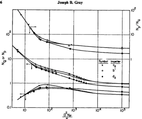
Values of NP and NQ for three impellers, c2, b\ and d2, are presented in Fig.
10 as a function of Reynolds number. The number of blades of impeller b' are half those of impeller b in Fig. 7. Here NQ rises with Reynolds number
FIG. 8. Effect of Reynolds number on tangential velocities produced by turbine (c2) in an unbaffled vessel.
Here Ζ is the vertical distance above the center of the turbine blades (N3).
fll/
» ι ι ι 1 ιLLI I
I1 1 1 1 ^ 1 %
n r T iJ 1 — l — ι — L _ L I 1
1— ι — ι — ι i ^ i x°0 5 i ) Cm 10 15 % 5 r >m 10 15 c
10
V A i&
ι0Γ A ^
/ j S ^ - / / j § ?
- Z = - J. 5 e m . / j Λ - ^9em. / / j
0.5- 6 ~ /0 d / 2 \
2
J ^^^^^ ^^T ^^T^
°û 5 \j C m 10 15 °0 5 r > c1 0 15 m
194 Joseph Β. Gray
4. Mixing in Agitated Vessels 195
FIG. 9. Effect of Reynolds number on radial velocities produced by turbine (c2) in an unbaffled vessel. Here Ζ is the vertical distance above the center of the turbine blades (N3).
when NRe is less than 102 and approaches a constant value for NRe above 103. Aiba (A2) has studied the effects of changing rotational speed a n d fluid viscosity on tangential velocities in a baffled and in an unbaffled 11 J-in. diam.
vessel with a 2-bladed, 4f-in. diam. impeller (b = f-in.) located l r V i n . above the vessel b o t t o m . H e obtained fluid velocities from measurements of the displacement of a steel ball suspended in the vessel by a thin wire. Fluid velocity was calculated from equations relating displacement of the ball and fluid velocity. T h e displacement of the ball from an equilibrium position at zero fluid velocity was determined from a calibration curve of counting rate of a Geiger tube and distance from the steel ball containing a small a m o u n t of cobalt 60.
The results are shown in Figs. 11 and 12 for a level 3 in. above the impeller.
The curve for velocities in the unbaffled vessel in Fig. 11 is similar to Fig. 8.
The points in this figure cover a range of NRe from 12,000 to 36,000 due to a rotational speed range of 50 to 150 r.p.m. F o r this range of rotational speeds, all points lie on the same curve and the velocity of the fluid is proportional to the impeller tip speed. T h e data in Fig. 8 indicate that a further increase in rotational speed does not change this proportionality between tangential
0 01 02 0.3(14 0 Oi 02 03 04 05 06 0 Q1 02 03 04 05 OS I — ι — τ — ι —ι ι —ι— ι — ι — ι — j — ι ι—ι—r ι ι — | —ι
U . I ' ' 1-5 «-* U- l__ 1
10 I 02 I 03 I C T I 0 5
D Np
FIG. 10. Correlation of discharge coefficients with Reynolds number for impellers in an unbaffled vessel (N3).
FIG. 11. Effect of impeller rotational speed on tangential velocities at Reynolds numbers greater than 12,000. NRc = 12,000 at Ν = 50 r.p.m. and NRe = 36,000 at Ν = 150 r.p.m.
(A2).
196 Joseph Β. Gray
4. Mixing in Agitated Vessels 197 0.6 ι
fluid velocity and impeller rotational speed. However, a large reduction of rotational speed or an increase in fluid viscosity which results in laminar flow and a NRC below 1000 results in a changing ratio of vtn/ND as impeller rota- tional speed is changed. This effect is illustrated in Fig. 12 for NRE from 67 to 270 and in Fig. 8 for NRQ from 14 to 830.
N a g a t a et ah (N2) determined the effect of adding baffles for six impellers under turbulent flow conditions. The flow pattern is more erratic with baffles than without baffles. Periodically, vortices are shed by the impeller and by the baffles. The centers of some of these eddies rotate slowly about the agitator shaft.
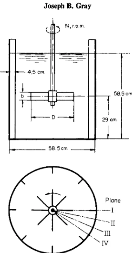
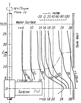
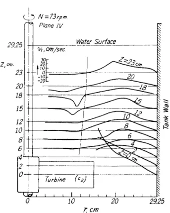
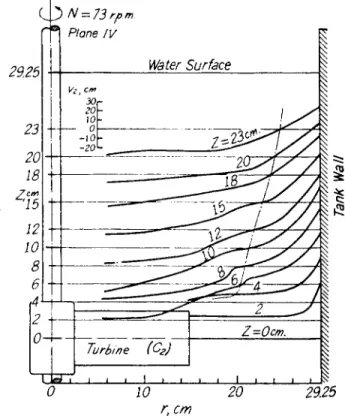
Typical average radial, tangential, and axial velocities for plane IV oriented as shown in Fig. 13 are shown in Figs. 14 to 17.
Tangential velocities are greatly decreased by insertion of baffles and b o t h radial and axial velocities are increased. These effects are illustrated in Fig. 17.
Aiba (A2) found a similar effect (Fig. 11). At one location inside the agitator periphery, the direction of flow is opposite to the impeller blades. This opposite flow is stated by N a g a t a , et al to be due to eddies which are caused by tangen- tial flow past the baffle plates. The eddies near the baffle plates die out rapidly but a smaller, more stable eddy is induced near the shaft by this temporary eddy.
The impeller discharge rate, Ql9 and the axial circulation, Q2, were calculated for flows produced by impellers in a vessel with 8 baffles at each of the planes I, II, III, and IV shown in Fig. 13. These flows are defined by Fig.
18 and the following equations:
198 Joseph B. Gray
Fig. 13. Baffled vessel used by Nagata et al. (N2) for velocity measurements.
Q1 = 4nrsjvrdZ (49)
ο
02 = 4TT j vzrdr (50)
ro
where r0, Z , Zp, and rs are defined in Fig. 18. The line B' — B" is a streamline through the upper corner of the impeller. The distance rs is arbitrarily chosen slightly larger than the impeller radius. As in Eqs. (43) and (45), the flows Qx
and Q2 are the total flows for both upper and lower halves of the vessel. Values of Qx and Q2 were calculated for each of the four reference planes I, II, III, and IV. Then the average Qx and Q2 were calculated. The results of these calculations are shown in Table III. The ratio of Q2/Q1 with baffles was found to be 1.8. Sachs and Rushton (SI) report a value of 1.96 for this ratio. An average value of Q2\Qx for a 16-blade paddle (a in Fig. 7) without baffles was, reported by Nagata ( N l ) to be 1.9 for various rotational speeds. Apparently fluid entrained by the stream leaving an impeller is not affected appreciably by the presence of baffles.
4. Mixing in Agitated Vessels 199
Plane IV — yr cm/sec
-20 0 20 4060 80100
1 1 1 I I I I I M I I
FIG. 14. Radial velocities produced by a turbine (c2) at 73 r.p.m. in a baffled vessel.
Turbine is located halfway between the water surface and the bottom of the vessel (N2).
TABLE III
Impeller Discharge Rate and Circulation Rate in Baffled Vessels"
Impeller Discharge performance Symbol
Ν <2i <22
Symbol Description (r.p.m.) (liters/sec.) (liters/sec.) β2/<2ι
c2 8-Flat-blade turbine 73 44 75 1.7
d2 8-Curved-blade turbine 73 39 73 1.85
g 8-Blade-arrowhead turbine 71 26.5 46.5 1.75
J 8-Blade, pitched-vane-type
impeller 72 25 44 1.75
aFrom Nagata et al. (N2).
200 Joseph Β. Gray
CVp N-73rpm.
Γ Η Plane IV
0 10 20 29.25 rt cm
FIG. 15. Tangential velocities produced by a turbine (r2) at 7 3 r.p.m. in a baffled vessel.
Turbine is located halfway between the water surface and the bottom of the vessel ( N 2 ) .
D a t a on the effect of baffles on impeller radial discharge, Ql9 are summarized in Table IV. The NQ values with baffles are 2 to 4 times the NQ values without baffles. F o r the same impeller diameters and rotational speeds, the NQ values are proportional to the discharge rate, Qx. The NP values are higher with baffles than without baffles. However, when the power to produce the same arbitrary, radial, discharge rate, of 0.265 ft.3/sec. is calculated for each impeller, one- sixth to one-half the power is required when baffles are used than when the same impeller is used with no baffles. The use of baffles increases the efficiency of obtaining a desired impeller discharge rate. The data in Table IV also show that the impellers which are more efficient in an unbaffled vessel are more efficient in a baffled vessel.
N o r w o o d and Metzner (N4) present a correlation of flow from 6-blade turbines in baffled, cylindrical vessels. In all cases, the following dimensions and ratios were the same.
4. Mixing in Agitated Vessels 201 Τ = 11.3 in.
b/D = 1/5 Baffle width = 0.1 Γ ZJT = 0.35 ZJT = 2.8
where Zi = distance of impeller center above the b o t t o m of the vessel, ZL = liquid depth. The impeller diameters ranged from 2 to 6 in., rotational speeds from 75 to 2300 r.p.m., and viscosities from 1 to 1780 cp. These conditions provided Reynolds numbers from 36 to 1.7 χ 104.
A thermistor probe was used in a Wheatstone bridge circuit for velocity measurement. The resistance of the thermistor was calibrated as a function of liquid velocity, viscosity, and density, using photographic measurements of velocity (M2, SI) in the region of a turbine impeller.
The flow rates were obtained by integration of the probe-measured velocity data using Eq. (43). In this case rs was selected where vz was zero.
FIG. 1 6 . Axial velocities produced by a turbine (c2) at 7 3 r.p.m. in a baffled vessel.
Turbine is located halfway between the water surface and the bottom of the vessel ( N 2 ) .
202 Joseph B. Gray
FIG. 17. Effect of baffles on velocities produced by a turbine (c2) at 72 r.p.m. Turbine is located halfway between the water surface and the bottom of the vessel (N2).
The volumetric flow data were correlated by the following equation with an average deviation of 9.7% :
Q = ΟΑΙΖΝΏ^Ώ^ρΙμ)™ (1 - &2)0·5 (51) For water agitated by a 6-in. diam. turbine with k = 0, bjD = 1/5, p = 62.4,
and/x = 0.040 lb./(ft.) (min.)
Q/ND* = 2.9 (52)
2. Directly Measured Discharge Rates
Rushton et al. (R3) measured the flow from propellers and turbines by placing the impeller near an orifice at the lower end of a draft tube which extended above the surface of the fluid in the vessel. The orifice diameter and distance from the impeller were selected to obtain maximum flow. Water was added to the draft tube at a rate which kept the level the same inside and out- side the draft tube. An outlet at the top of the tank allowed the water to leave as fast as water was added to the draft tube. The rate of flow of water added to the draft tube was assumed to be the total discharge flow from a propeller.
4. Mixing in Agitated Vessels 203 Ζ
FIG. 18. Reference points for calculating impeller discharge rates or velocities in baffled vessels ( N 2 ) .
F o r a turbine, half of the turbine flow came from below the turbine and half from above through the draft tube.
The propeller discharge performance data may be expressed in the form
Q/ND2p = 0.42 (53)
where ρ is the propeller pitch.
However, the average deviation of values of this constant was 0.06 for eight propellers from 3f to 12f in. diam. The results are correlated better by the equation
Q/ND2 = 0.26 (54)
In this case, the average deviation of the constant is 0.02.
In a later paper, Rushton and Oldshue (R4) reported that further experi- mental results showed that the flow from geometrically similar marine pro- pellers varied as Z>3. N o data were presented to support the equation given.
Q/ND3 = 0.40 (55)
Sachs and Rushton (SI) present discharge data for a 4-blade turbine. In this case
Q/ND* = 0.47 (56)
TABLE IV
Effect of Baffles on Impeller Discharge Performance"
Impeller type Flat blades Curved blades Arrowhead Pitched-vane Pitched blades Flat blades
Impeller Symbol 8 J PI
Baffles 8 0 8 0 8 0 8 0 8 0 8 0
NQ 1.34 0.34 1.20 0.43 0.83 0.26 0.78 0.34 0.87 0.31 2.9 1.23
NP 9.5 0.95 3.8 0.71 7.7 0.95 1.05 0.44 2.8 0.72 14.2 2.17
NPINQ 7.1 2.8 3.2 1.7 9.3 3.7 1.3 1.3 3.2 2.3 4.9 1.8
Power, ft. lb./sec. for 0*265 ft.3/sec. 0.15 0.93 0.083 0.34 0.515 2.08 0.086 0.43 0.165 0.93 0.170 0.34
NBE x ΙΟ"5 1.3 1.0 1.3 1.0 1.0 1.0 1.0 1.0 1.3 1.0 0.76 0.37
"From Nagata ET AL (N2).
204 Joseph B. Gray
4. Mixing in Agitated Vessels 205 Rushton et al. (R3) obtained flow data for a 6-in. diam. turbine in a baifled vessel using a draft tube to measure flow. The following equations summarize the results;
3. Discharge Rates From Tracer Circulation Times
M a r r ( M l ) made measurements of the times for a rubber particle with a density nearly the same as water to make successive passes through a horizon- tal plane perpendicular to the shaft at the center of a propeller. The measured times were made up of the relatively short times for the particle to move from the propeller through the part of the vessel below the propeller, and the longer times for transit through the part of the vessel above the propeller. The flow produced by the propeller is given by the total fluid volume in the vessel divided by the average transit or circulation time for the rubber particle to pass through the propeller cross section through all parts of the vessel and back through the propeller cross section. The flow rate obtained in this way does not include the fluid entrained by the jet leaving the propeller.
These measurements were made using water in an l l j - i n . i.d. cylindrical vessel with three vertical baffles. Five sizes of propellers from 2\ in. to 5 in.
diam. were used 4f in. above the bottom of the vessel. The fluid volumes ranged from 0.53 to 0.73 cu. ft. and the propeller speeds from 300 to 900 r.p.m.
M a r r selected a value for Q/ND3 of 0.61 from the tests with a volume of 0.53 cu. ft. Higher values of Q/ND* obtained at larger fluid volumes were attributed to regions in the vessel where the fluid velocity was too low to assume that the rubber particle with a specific gravity of 0.98 was unaffected by gravitational force.
By using a different type of tracer method, Holmes et al. ( H I ) obtained data on circulation times which were used to calculate turbine discharge rates for water and aqueous glycerine solutions. They injected a pulse of sulfuric acid into the center of the turbine and measured the electrical conductivity of the fluid leaving the turbine periphery. Peaks of decreasing amplitude were ob- served each time the pulse passed by the conductivity measuring probe. The time intervals between adjacent peaks were averaged to obtain a time of transit or circulation time, 9C.
In these experiments, 8 | , 23 J , and 3 9 \ in. diam. flat-bottomed vessels were used in which: (a) the liquid depths were equal to the vessel diameter; (b) a 6-blade disk turbine was used with a diameter: blade length: blade height ratio of 20: 5: 4 ; (c) equal volumes of liquid were above a n d below the
F o r 3 blades, Q/ND3 = 0.50 F o r 4 blades, Q/ND3 = 0.59
(57) (58)
Q/ND3 = 0.61 (59a)
206 Joseph Β. Gray
Curved-blade turbine Q/ND* = ^(bjD) sinjS-y/l-A:2 (24)
Q/NDZ = Tr\b/D) \/2k(\-k) (21)
Flat-blade turbine Q/ND* = 0.418(6//)) (1 -*)°-5(Z)0-V//*)0'5 (51) Pitched-blade impeller Q/ND* = ττ2(1 —k) (1/6 sin γ cos y + bjD sin2y) (34) Propeller Q/ND* = llS(a>-a>L)(plD)D* [1 - ( p ^ D2) \ n (1 + π2D*/p2)] (39)
the left-hand side of the equation. The value of k which appears in many of these equations must be obtained from experimental data. Equation (27) provides a method of estimating k.
k = NPli^NQ (27)
As a basis for comparing the discharge rates for impellers by the various methods, values of the dimensionless flow rate, Q/ND3, have been calculated using the equations in Table V and the results of various experimental studies.
The values of QjND3 and conditions of operation are presented in Table VI.
The values of QjND3 for propellers range from 0.40 to 0.61 when deter- mined experimentally. The value of 0.60 predicted from Eq. (39) derived by Van de Vusse assumed ω J ω = 0, and pjD = 1.
t u r b i n e ; (d) four vertical baffles were used which were 0.1 of the vessel diam- eter.
Holmes et al found that
ΝΘΧΌ/Τ)2 = 0.85 ± 0.05 (59b)
above Reynolds numbers of 104. The value of 0C in this relationship can be used to calculate the liquid pumping or discharge rate of the turbine. The pumping rate, qp9 is equal to the tank volume, ττΖ)3/4, divided by the average time, 0C, for tracer to pass from the turbine periphery through the liquid in the vessel a n d back to the turbine periphery.
Q = ( π Γ3/ 4 ) / ( 0 . 8 5 Γ2/ Α Φ2) = Q.93ND3(TjD) (59c) When TjD = 2.0, Q = 1.9ND3 and for TjD = 3.0, Q = 2.87V/). These
results compare favorably with those of N o r w o o d and Metzner as shown by Eq. (52). Although the ratio, TjD, does not appear in Eq. (51), the results of Holmes, et al indicate it should.
C . COMMENTS ON IMPELLER DISCHARGE D A T A
The equations which have been developed for flow from impellers are summarized in Table V. In all cases, a dimensionless flow rate, Q/ND3, is on
TABLE V
Summary of Equations for Flow from Impellers
Eq Impeller type Equation
TABLE VI
Comparison of Discharge Rates of Impellers
No. of No. of Speed NREX Eq. or
Impeller type blades D\Ta b\Db ZJT ZL\Td baffles D(in.) r.p.s. 10~5 Table Ref.
Propeller (pe) 3 e 6 1.6 0.40 (55) (R4)
Propeller (p = 1) 3 0.2-0.6 0.4-0.8 0.7-1.1 3 2-5 5-15 0.4-2 0.61 (59a) (Ml)
Propeller 3 0.17-0.6 4 3.6-12.3 2-15 0.42/ (53) (R3)
Propeller (p = 1) 3 e 0.47 (42) (B3)
Propeller (p — 1) 3 e 0.60 (40) (VI)
Turbine 4 1/6 1/5 0.45 1.33 4 6 5-7 1-1.7 0.59 (58) (R3)
Turbine 3 1/6 1/5 0.45 1.33 4 6 6-10 1.5-2 0.50 (58) (R3)
Turbine 4 0.35 1/5 0.35 1.04 4 4 1.7-3.3 0.17-0.34 0.47 (SI)
Turbine 6 0.53 1/5 0.35 2.8 e 6 2.9 (51) (N4)
Turbine 6 0.50 1/5 0.50 1 4 10 1.9 (59c) (HI)
Turbine, c2 8 0.51 1/5 0.50 1 8 11.8 1.45 1.3 1.34 IV (N2)
Turbine, c2 1/5 e 1.25 (21,27)
Turbine, px 8 0.31 1/3 0.50 1 8 7.1 2.3 0.76 2.9 IV (N2)
Turbine, ρλ 1/5 e 2.3 (21,27)
Pitched blade, kz 8 0.51 0.14 0.50 1 8 11.8 1.3 0.87 IV (N2)
Pitched blade, k3 0.14 1 (34,27) (VI)
Turbine, d2 8 0.51 1/5 0.50 1 8 11.8 1.3 1.2 IV (N2)
Turbine, d2 1/5 1.26 (21,27)
a DjT — ratio of impeller diam. to vessel diam.
b b\D — ratio of blade width to impeller diam.
c ZJT — ratio of axial distance from impeller center to bottom of vessel to vessel diam.
d ZjjT — ratio of liquid depth to vessel diam.
e Not specified.
N0 = 0-42 ND2p. κ>
4. Mixing in Agitated Vessels