ANALYSIS OF A MEGAWATT LEVEL DIRECT CONDENSER -RADIATOR Richard P. Krebs,* David M. Winch,*
and Seymour Lieblein"'*
NASA Lewis Research Center, Cleveland, Ohio Abstract
An analytical study of a nonredundant direct condensing finned-tube radiator for a 1-Mw Rankine electrical power gener- ating system shows that the radiator weight may be close to 6000 lb. This radiator was assumed to use beryllium fins and armor over a columbium alloy tube liner. Protection against damage from meteoroid impact, for the criteria used, consti- tuted the major portion of the total weight. The study indi- cates the effect of tube diameter, number of tubes, and seg- mentation into nonredundant panels on the radiator weight and pressure drops. Header weights are of such magnitude that they should be considered in radiator design and analysis. Appli- cation of nonredundant segmentation results in some weight saving.
Nomenclature A = area, ft2
a = finite plate thickness and spalling correction factor Cp = specific heat, Btu/lb-°F
c = velocity of sound, fps D = diameter, ft
d = diameter of meteoroid E = Young's modulus, psf
F = radiant interchange efficiency g = acceleration of gravity, ft/sec2 h = heat of condensation, Btu/lb
J = mechanical equivalent of heat, 778 ft-lb/Btu K = ( qt + 2qf)/G(JjtDiT*4
k = thermal conductivity, Btu/ft-hr-°F
Presented at the ARS Space Power Systems Conference, Santa Monica, Calif., September 25-28, 1962.
^Research Engineer, Flow Processes Branch.
fChi ef, Flow Processes Branch.
KREBS, WINCH, AND LIEBLEIN
L = tube length, ft P = pressure, psf
p(0) = probability of no penetrations, 0.9
Poo = normal penetration into an infinitely thick plate QY = heat radiated, Btu/hr
q = heat radiated, Btu/hr-ft
R1 = fraction of flow area occupied by one phase R = gas constant, ft-lb/lb-°F
Re = Reynolds number T = temperature, °R t ~ fin thickness, ft u = velocity of vapor, fps V = velocity of liquid, fps
V = average meteoroid velocity, fps W P= weight, lb
W = weight flow per tube, lb/sec w ?= half-fin width, ft
wr = panel width, ft
a = constant in mass distribution, 2.54X10"9 gmP/ft2-day B = constant in mass distribution, IO/9
6 = wall thickness, ft e = emissivity
T] = efficiency
6 ~ Mach number exponent
\i = viscosity, lb/ft-sec p = density, lb/ft3
a = Stephan-Boltzmann constant, 1.713X10"9 Btu/ft2hr-°R4 T = time, days (500)
Ф = two-phase flow parameter ф ?= density ratio exponent X = two-phase flow parameter Subscripts
a = armor
c = columbium liner f = fin
g = vapor or gas phase i = inside
L = liquid phase LH = liquid header m = momentum
o = tube outer surface p = meteoroid particle
TOT = total flow, liquid + vapor t = target, or tube
VH = vapor header
Superscript
* ?= static conditions at tube inlet Introduction
The generation of electric power in space in amounts of the order of 1 Mw or more appears to be a formidable task today.
Currently, a leading contender for the power source is a gener- ator driven by a turbine operating in a Rankine vapor cycle and using one of the alkali liquid metals as a working fluid.
One of the problems associated with such a cycle is the rejec- tion of waste heat which may amount to around 15X10^ Btu/hr for each megawatt of electric power generated.
The heat to be rejected is in the vapor exhausting from the turbine. In one design approach, the vapor passes through a direct condenser-radiator, which for this discussion is assumed to be of the finned-tube type in the form of a flat plate with beryllium fin and armor. The vapor is condensed in the radi- ator tube, and the liquid condensate is subcooled. The heat rejected leaves the cycle by radiation from the outer surfaces of the tubes and fins.
The area required to reject this heat has been calculated by many researchers.1~3 For a cycle using representative com- ponent efficiencies and turbine inlet temperatures between 1800° and 2000°F, the radiator may require an isothermal sur- face area, or prime area, of between 1400 and 1000 ft2, re- spectively, for a system producing 1 Mw of electrical power.
Because this radiator is to be used in space, where it may be hit by hypervelocity meteoroids, the radiator tubes must be protected against meteoroid penetration and impact damage.
Such protection adds considerably to the weight of the radi- ator, making it one of the heaviest components in the power generating system. ^ ^ Some specific calculations on the rela- tive weights of protected and unprotected radiators^ have in- dicated that at the 1-Mw level the protected radiator weight may be more than four times that of an unprotected radiator
even when the chief constituent is beryllium. Some two tons or more of radiator were indicated for the generation of 1 Mw of electricity.
One way of reducing the radiator area is to increase the tur- bine inlet temperature (peak cycle temperature). If the state of the art for materials in the turbine can be advanced, higher peak cycle temperatures can be used. However, it does not
KREBS, WINCH, AND LIEBLEIN
follow that weight savings in the radiator automatically will result. It has been pointed out in fief. 7 that, if the radi- ator temperature exceeds that at which beryllium can be used, it may be necessary to use materials of higher density. In this event, weight increases may be introduced which are pro- portionately greater than the decrease in weight due to area reduction.
Other factors that affect the weight of the radiator are the amount of subcooling required, the working fluid used, and the geometric arrangement of the radiator. It is this last facet with which this paper primarily is concerned. In the geo- metric arrangement are included such items as the number of
tubes, the inside diameter of the tubes, and the number of nonredundant panels into which the radiator is divided. If these three parameters are considered to be independent, then the dependent parameters are the flow velocity in the tubes, the tube length, the aspect ratio of the panel or panels, the pressure drops in the tubes and headers, and the radiator weight. It is the purpose of this paper to show how these de- pendent and independent variables are interrelated in an illus- trative Rankine cycle.
Analysis
In order to illustrate the effect of changes in geometry on the radiator weight and pressure drop, a single power level and cycle were chosen. The power level was kept at 1 Mw, and the cycle parameters were fixed at the values given in the succeeding section.
Cycle
Potassium was chosen as the working fluid in the cycle. A peak temperature of 2000°F and a radiator temperature of 1240°F were used. (For the assumed turbine inlet temperature, the radiator weight curve reaches a minimum near a radiator inlet vapor stagnation temperature of 1240°F.) The vapor pressure of potassium corresponding to this temperature is about 6 psia, which affords a sufficiently high pressure level so that pump- ing problems are not aggravated. The radiator tubes were made sufficiently long to provide 25° of subcooling to the conden- sate. No further heat was extracted from the radiator to pro- vide coolant for the components. The emissivity of the coat- ing on the fins and tubes was taken to be 0.90, and the effec- tive sink temperature for the radiator was assumed to be 0°R.
Turbine and generator efficiencies of 0.75 and 0.90, respec-
tively, were assumed in this analysis. Ten percent of the generator output was assumed to be required for accessories and controls. The foregoing values plus the cycle tempera- tures , working fluid, and the power level determined the total heat rejection rate and the mass flow rate of the working fluid.
Configuration
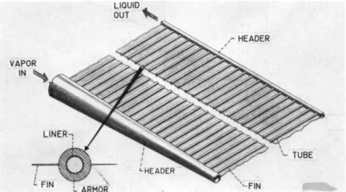
The radiator panel is of the finned-tube type shown in Fig. 1.
The tube consists of a thin-walled liner of columbium alloy, exposed to the working fluid, and a beryllium armor sleeve surrounding the liner. The liner thickness was made an arbi- trary function of the inside diameter given by
6C = 0.04 Dj_ (1)
Minimum wall thickness was taken as 0.020 in. for the l/2-in.- i.d.-tube. This thickness is compatible with current fabrica- tion capabilities and is believed to be about the minimum wall thickness that can be welded into the headers. This minimum columbium alloy liner also must be thick enough to withstand the corrosion of the liquid metal and to act as a diffussion barrier between the beryllium and the liquid metal. The wall thickness was increased as the inside diameter was increased because it was felt that larger diameters inferred longer tubes and the additional wall thickness would provide the nec- essary stiffening and strengthening of the tubes.-
The beryllium armor thickness was calculated from the equa- tion given in the following subsection. The fins were sized to provide minimum panel weight for a given heat dissipation.
Wet vapor from the turbine is fed to the radiator panel by means of a vapor header in the form of a hollow paraboloid.
The parabolic shape insures constant vapor velocity in the header. The header has a columbium alloy liner. The liner thickness should be a function of fabricability, rigidity, and hoop strength. An appropriate value for the liner thickness cannot be determined until a final header design is conceived.
Accordingly, a liner thickness of 0.12 in. was assumed somewhat arbitrarily and held constant in this analysis. The beryllium armor thickness on the vapor header was made equal to the
thickness on the radiator tubes. The total heat to be radiated, as determined by the cycle calculation, was proportioned be- tween the panel and the vapor header. The quality in the tur- bine exhaust was decreased by an amount proportional to the heat radiated by the header, and the value of the quality thus
KREBS, WINCH, AND LIEBLEIN
computed was used at the entrance to the radiator tubes.
For simplicity, the liquid header was designed with a con- stant diameter with a maximum liquid velocity of 4 fps at the outlet. The value of maximum liquid velocity was selected so that the pressure loss in the liquid header amounted to about 0.025 of the pressure at the end of the radiator tubes.
The columbium liner for the liquid header follows the same schedule with inside diameter as do the tubes• However, a maximum liner thickness is set at 0.12 in. The liquid header also has a beryllium armor thickness equal to that for the tubes and vapor header. No heat radiation or subcooling is credited to the liquid header.
Meteoroid Protection
The assumptions used to determine the meteoroid protection required for the radiator tubes have been taken from a compre- hensive and definitive appraisal of the data and theories available concerning the meteoroid penetration phenomenon.
This appraisal, prepared at the Lewis Research Center, has been reported in Ref. 6. The assumptions used in this analysis are as follows:
1) Meteoroid properties
a) The cumulate frequency of particles m grams or smaller per square foot per day (Refs. 6 and 8) is written as
F> = am-P
where a = 2.54X10"9 gmP/ft2day, and p = 10/9
b) The meteoroids are oriented isotropically with respect to the radiator surface, and have a density of 2.7 gm/cm3
(169 lbs/ft3) and an average velocity of 30 km/sec (98,400 fps).
2) Penetration criterion
a) In the general formula for normal penetration into an infinitely thick plate
PTC = 2 d t P p / p ^ V / c )0 (2) where the density ratio exponent ф = l/2, the impact Mach
number exponent 6 = 2/3, sonic velocity is defined as
c - -/E-j-g/p-j-, and c is a function of temperature through the
6a = 2a|
target modulus of elasticity E^ and the target density pt. For oblique impacts, the depth of penetration was assumed de- pendent upon the normal component of the velocity.
Ъ) A correction factor a was applied to the depth of pene- tration given Ъу Eq. (2). This correction factor took into account the facts that the tube wall was of finite thickness and that spalling of the inside wall was not to Ъе tolerated.
The required wall thickness then was given Ъу
&a = aPoo (2a)
For this analysis, a value of 1. 75 was used for a.
In Ref. 6 all of the foregoing assumptions are combined, and the resultant equation for the armor thickness 6 is given Ъу
^ p \
l / 2/ v f /
5/ e . 7 4 7 x l 0 -
5\
l / 3r оАт " l
1/ ^ / 2 YAP
ft) \c) \ pp ) [-In P(0)J \Ъвр + 2)(3) where the density and velocity ratios are dimensionless. In this equation the diameter of the meteoroid has been written in terms of its density pp(gm/cm3) and the meteoroid population parameters a and p, as well as the vulnerable area A. The mission time т = 500 days, and the probability of no tube pene- trations P(0) = 0.9. The factor [2/(30(3 + 2) ]l/3p is the oblique penetration correction factor. For this analysis, the vulnerable area was taken as the outer surface area of the armor. *
Weight Minimization
Panel. The design of a radiator tube panel having a minimum weight per unit heat rejection followed the procedure given in Ref. 9. Other procedures have appeared in Refs. 10 and 11.
Variables that had to be selected in order to use this design approach included the material for the fin, tube, and liner;
the fluid temperature inside the header; the total heat rejected
^Recent meteoroid flux measurements show that the values of the parameters in the equation for cumulate frequency should be a = 0. 53Х10-Ю and p = 1. 34, while the meteoroid density is about 0.44 gm/cm3 (Whipple, Fred L. : "On Meteoroids and Pene- tration," Interplanetary Missions Conf., Ninth Annual Amer.
Astro. Soc. Meeting, Los Angeles, January 15-17, 1963). This flux reduction permits an increase in the probability of no penetra- tions to about 0.998 for the same radiator weights given herein.
KREBS, WINCH, AND LIEBLEIN
by panel and header; and the mission parameters, such as the duration of mission and the probability of no punctures of the radiator tubes.
The procedure of Ref. 9 includes the following assumptions:
1) The tube liner wall temperature is equal to the vapor static temperature at the tube inlet.
2) The fluid and wall temperature is longitudinally constant along the tube. (The effect of the temperature drop accompany- ing the pressure drop along the tube will be discussed in a later section.)
3) There is no temperature drop across the tube liner wall.
4) The temperature drop in the tube armor is radially one- dimensional.
5) Radiant heat interchange exists between fin and tube.
6) Longitudinal heat conduction in the fin is one-dimensional.
7) The fin and tube radiating efficiencies are constant.
8) The effective sink temperature for the radiator is absolute zero.
9) The values for the physical and thermal properties of the fin and armor materials are based on the radiator inlet total temperature.
The design procedure requires the simultaneous solution of four equations. The first equation is for the armor thickness, repeated from the preceding section. In Eq. (З) the vulnerable area of tubes and vapor header, A, is expressed in terms of the heat to be radiated and the fin and tube geometry:
A i f , . *
(Di
+ 2 5c
+ 2 5аЧ , -,
д,
(.
~ a £ T4 l2[Tlt(Di + 2бс + 26a) + 1.1 Ffw] + *-- Г W The second and third requirements state the conditions that the half-fin width and thickness, w and t, respectively, must meet in order for the panel to be of minimum weight for a given heat rejection:
8.85 PfgeT^ 19.2 pf( D1 + 26c + 28a)T)tqeTg
k ^ + Щ ^
- rt[pcSc(Di + Sc) + Pt5a(Di + 2SC + B J ] = 0 (5) and
2 а е Т ^
t - ^nhr ^
The fourth equation expresses the relation between the tube outer surface temperature and the static temperature of the flowing fluid (tube inner surface):
oe(B± + 2oc + 2oa) 44 (j)± + 25 /Di + 25cc + 25 + 2oa\ , -
T
o ^Д D
i +2o
c)
+ k<
To - * )
(7) The simultaneous solution of Eqs. (3 and 5-7) yields the half- fin width w, the fin thickness t, the armor thickness 5a, and the surface temperature T0. The combined length of all the tubes in the panel is then given by
L *- 5 r é < 8 >
and the panel weight by
¥ = J 2 pft w + K[pcSc(Di + Bc) + PtSa(D± + 2 5c + 5 j ] i L*
(9) It should be noted that for this analysis the weight of the panel is dependent upon the total tube length Ii* and is in-
dependent of how this total length is broken up into parallel flow passages to form a panel.
Headers. A choice of panel width w! must be made before header design can proceed. The selection of a panel width usually is based on flow velocity and pressure drop considera- tions in the panel, as will be shown in the Results section.
It already has been pointed out that the panel weight minimi- zation program requires the heat rejected by the vapor header
KREBS, WINCH, AND LIEBLEIN
and the fluid temperature inside the header as two of the in- put parameters. The surface area of the vapor header thus is
determined, and the diameter of the header then becomes a de- pendent variable that is determined by the following relation after the panel width wf is known:
^ - 2.09 ^ W Fr a < 1 0 >
where for simplicity it is assumed that Туц = T0. The accept- ability of the diameter thus computed will depend on the re- sultant vapor header velocity and pressure drop. Equation (lO) as well as the remaining equations in this section are for a single panel configuration only in which the turbine vapor is introduced into the center of the vapor header and flows toward either end, and the liquid condensate is withdrawn similarly from the center of the liquid header.
The weight of the vapor header is given by Wr a = ( з / з ^ Б у н + &vHc)(w? + 5VHc)6VHcPc
+ (J>VH + 25VHc + 5a)(^' + 26унс + 6a)saPt] (ll) and that of the liquid header by
WHÍ = ^{(pLDLH/é) + Pc5LHc(DLH + 5LHc)
+ Pt6a(»LH + 5a + 25LHc)] (12) The total radiator weight is obtained by summing Eqs. (9, 11,
and 12).
Pressure Drop
Radiator tubes. The pressure drop in the radiator tubes where flowing vapor is condensing was computed from a combina- tion of several basic flow and energy equations. Pressure drops were computed for a series of incremental tube lengths, and the pressure drop for the whole tube was obtained by sum- ming the incremental drops. The flow model used was that of Ref. 12, in which it was assumed that, at any given section perpendicular to the flow direction, the temperature and
pressure in both the liquid and vapor were uniform and the same for both phases. In this flow model it was assumed that the velocities of the liquid and vapor were uniform in each phase
at a given cross section, but that the two velocities were not necessarily equal. Flow velocities were sufficiently high that both phases met the criterion of Ref. 12 for turbulent-
turbulent flow over a considerable portion of the tube length.
The experimental data of Ref. 12 show a spread of about ±40$
around the analytical results. Subsequent investigators have found the predictions of Ref. 12 to give pressure drops higher than the experimental data (e.g., Ref. 13).
The fundamental energy and flow relations used to find the pressure drop were as follows:
1) The energy equation, which set the heat radiated equal to the heat liberated by the formation of the liquid less the in- crease in sensible heat and kinetic energy of the liquid and vapor:
Kea*D,T^ . , . ч ^ diw-rV2 + W >2)
-ggggP- to = h dw
L- (c
pLw
L +c
pgw
g)dT* - N
2Jgg /
(13) 2) Clapeyron's equation, which relates the change in tempera- ture to the change in pressure for a saturated vapor:
dT = T dP/jhpg (111)
3) The continuity equations for liquid and vapor. In the differential form, it was assumed that the density was constant over the small increment in the tube length dx:
d
V^L
=(
dV/v)
+(
ffil/
RL)
dWg/Wg = (du/u) + (đRg/Rg)
4) The Lockhart-Martinelli12 correlation for the fraction of tube area occupied by the liquid and vapor:
4 = H£(x)
(16) Rg = i - «L
5) The friction pressure drop as computed by Ref. 12:
KREBS, W I N C H , AND LIEBLEIN
2 0.092Ц
- đPf = Og - 3 — £ ( R e g )1'8 dx (17)
S DiSPg
where Re^. = 4Wg/:rrDj_|Lig, and <£g i s a function of X.
6) The d i f f e r e n t i a l form of t h e change i n p r e s s u r e due t o a change i n momentum:
- ^ т = d(pLALV2) + d(pgAgu2) (l/gA) (18) By combining Eqs. (13-18) and letting T0 = T* = T for sim-
plicity, a relation between the increment of tube length and the increment of condensate formed can be written:
Jg \ dX R£Wg yl' Jg y dX R^WL I Jhpg dWL
(19) Equations (17-19) are solved simultaneously for dW^, àPm, and dPf. Total change in pressure for each increment can be found from
dP = dPm + dPf (20)
and the total pressure change for the entire radiator tube can be found from summing the incremental changes.
Headers. The pressure drop in the vapor header for a single- panel configuration, described in the preceding subsection, was taken for simplicity as
0.00357 p^vfrrrw1
where Vyjj is the uniform vapor velocity in the header (based on the turbine exhaust quality and neglecting the flow area occupied by the liquid) and Re is the vapor Reynolds number based on the vapor header maximum diameter. The foregoing pressure drop has been computed as though the flow were single phase, whereas the presence of the liquid phase will increase
the pressure drop over that calculated.
The pressure drop in the liquid header was calculated from 0.000794 pTV?TrWT
^ T H = n ^ (22) In this equation Re is the Reynolds number in the liquid
where the velocity VJJR is a maximum, that is, 4 fps. This maximum velocity occurs at the liquid header outlet.
Two other pressure drops have been neglected in this analysis.
These are the drops due to changes in flow conditions at the junction of the vapor header and the tubes and at the junction of the tubes and the liquid header (tube entrance and discharge losses).
Results
The results of this analytical study show the effect of changes in panel geometry and nonredundant segmentation on the total radiator weight and pressure drop in panel and vapor header. Emphasis is put upon those changes in the major vari- ables that have large effects on the weight but at the same time provide specified pressure drops in the tube panel and vapor header.
Tube Diameter
The inside tube diameter was the first panel geometry vari- able studied. The effect of changes in tube diameter on radi- ator tube panel weight is shown in Fig. 2. Sizeable increases in tube panel weight can result from increases in the tube diameter. These increases come from at least three different sources. First, as the tube inside diameter increases, the tubes become heavier even though the liner and armor thickness are held constant. Second, the liner does increase in thick- ness according to Eq. (l). Third, the armor must be increased because the vulnerable area has been increased due to the larger surface area (Fig. 2).
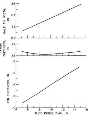
It may be of interest to note the effect of the increase in tube diameter on armor thickness, fin width, and fin thickness, as shown in Fig. 3. Largest changes are observed for the fin dimensions.
KREBS, WINCH, AND LIEBLEIN
Tube Pressure Drop
The effect of tube diameter and number of tubes on pressure drop in the tubes is shown in Fig. 4. Superimposed on the figure are lines of constant vapor velocity at the tube inlet.
Perhaps the most interesting feature of this figure is that the tube diameter effectively sets the number of tubes for a large range of pressure drop. Stated in a different way, for a fixed tube diameter the pressure drop increases very rapidly as the number of tubes is reduced. Part of this extreme sensi- tivity can be traced to the fact that the pressure drop is the difference of two large pressure changes: the friction pressure loss and the pressure rise due to the recovery of the momentum in the vapor. The difference of these pressure changes is proportional to the square of the velocity.
It is seen in Fig. 4 that the pressure drop in the tube panel can be eliminated, or even reversed, by increasing the number of tubes for a given diameter. However, a qualitative analysis indicates that some pressure drop may be necessary in the tubes of a multitube condenser-radiator in order to assure flow stability. Without the pressure drop, the instability may be- come so severe that one or more tubes would fill completely with vapor. If the vapor were to enter the liquid header and proceed into the pump, it could impair the pump performance.
Instabilities also could disturb the inventory balance between the radiator and the boiler. Inasmuch as the amount of pres- sure drop required to produce acceptable stability has not been determined precisely, a value of 0.05 of the pressure at the tube entrance has been chosen arbitrarily for illustrative uses in this report.
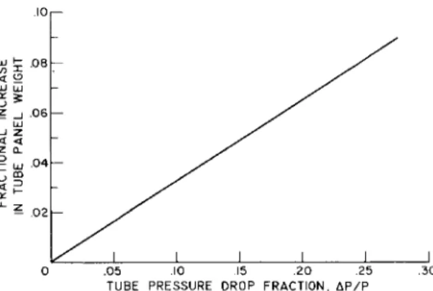
In this analysis the effect of the tube pressure drop on radiator weight has been neglected. When there is a pressure drop in a tube filled with condensing vapor, there is also a temperature drop, given by Eq. (14). The decrease in tempera- ture requires an increase in radiator tube length in order to reject the required amount of heat, and this increase in length increases the weight. The fractional increase in tube panel weight which can result from a pressure drop is shown in
Fig. 5 as an example. It is seen that weight increases will be small for pressure drop fractions (ЛР/р) of the order of 0.05.
The velocities that yield pressure drops of interest are high.
The momentum pressure that can be recovered from these high velocity flows is also high and is recovered in a relatively short length of condenser tube with the high heat rejection rates encountered in the finned-tube radiator. With the fin
and large amount of armor on the tube for the configuration considered, the heat rejection rate is increased from 3 to 7 times that of a thin-walled tube of the same inner diameter.
Within the ground rules of this analysis, it would seem that only with very large-diameter tubes is it possible to achieve a pressure drop with relatively low vapor velocities.
If experimental evidence is obtained in the future which in- dicates that a pressure drop is not necessary in order to achieve flow stability, then it would seem to be possible to reverse the pressure drop and realize a pressure rise. Such a rise could reduce the radiator tube panel weight just as the pressure drop increased it (Fig. 5).
Tube Panel Geometry
Previously it was shown that tube panels employing small- diameter tubes result in lighter panel weights. Figure 4 also shows that, for a given pressure drop, a reduction in the tube diameter necessitates an increase in the number of tubes. As long as a single panel is used, an increase in the number of tubes implies an increase in header length. However, if the tubes can be arranged in two or four panels, as shown in Fig. 6, then for a fixed header design the number of tubes can be
doubled, or for a fixed number of tubes the size and/or pres- sure drop in the header can be reduced. If the number of tubes is increased, the tubes will become shorter and the inside diameter will decrease, which should decrease the tube panel weight. However, the two- and four-panel arrangements require additional liquid headers. The actual weight savings to be realized by substituting a two- or four-panel arrangement for the single panel can be determined only after both the tube and header weights and pressure drops have been computed. A later section will discuss the results of these computations.
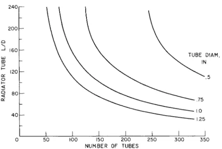
The relations between the tube diameter, number of tubes, tube inlet velocity, and pressure drop shown in Fig. 4 are un- changed by the panel configuration. The relation between the tube length, expressed as a multiple of the tube diameter, and number of tubes is shown in Fig. 7 for several tube inside diameters. In general, for a fixed tube diameter, the length decreases as the number of tubes increases so as to maintain approximately the same radiating panel area. In other words, the L/D varies inversely as the number of tubes, and this re- lation is independent of the panel configuration.
The individual panel widths are plotted against the number of tubes for several tube diameters for a single panel in Fig. 8.
KREBS, WINCH, AND UEBLEIN
For a fixed tube diameter, the panel width increases linearly with the number of tubes; and for a fixed number of tubes, the panel width increases with an increase in tube diameter. Also, for the same number of tubes, the width of each panel in the two-panel configuration is one half that in the one-panel con- figuration, and the width for four panels is one half that for two panels.
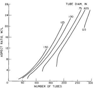
Panel aspect ratio is defined as the ratio of panel width to tube length. Figure 9 shows the panel aspect ratio plotted against the number of tubes for several tube diameters for the single-panel configuration. Since the panel width increases linearly with number of tubes (Fig. 8) and the tube length varies inversely with number of tubes (Fig. 7), the quotient, or aspect ratio, should vary as the square of the number of tubes.§
For a fixed number of tubes, the aspect ratio increases nearly as rapidly as the tube diameter. Although there is some in- crease in panel width as the tube diameter increases (Fig. 8), the increase in aspect ratio largely is due to the decrease in length with an increase in tube diameter as indicated by Fig. 7.
Thus, for low panel aspect ratio, large tube diameter and low number of tubes are indicated.
For a fixed number of tubes, changing from a one- to a two- panel configuration reduces the aspect ratio by a factor of two; changing from a two- to a four-panel configuration de- creases the aspect ratio by another factor of two. In general, the aspect ratio varies inversely as the number of panels for a fixed number of tubes. Thus, paneling can be used effec- tively to reduce aspect ratio.
For a fixed header length, the number of tubes in a two- or four-panel configuration is double that for a single panel.
The aspect ratio doubles in going from a single- to a two-panel arrangement. The aspect ratio is the same for the one-panel and four-panel for a fixed header length.
As indicated in the previous curves, a continuum of geome- tries is available through a choice of tube diameters and
§The inflection in the aspect ratio curves as number of tubes is reduced is attributable to the accompanying increase in flow velocity. The increase in flow velocity reduces the fluid static temperature and the radiator surface temperature, which requires an increase in tube length, or a decrease in aspect ratio, in order to reject the given amount of heat.
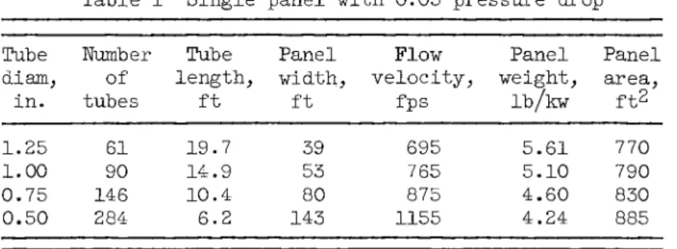
number of tubes or aspect ratio. However, a series of geome- tries can be chosen which have the same pressure drop in the radiator tubes. A pressure drop of 0.05 has been chosen arbi- trarily to illustrate how geometry and tube panel weight vary for a fixed pressure drop. Pertinent information regarding a single panel with 0.05 pressure drop is given in Table 1.
Table 1 Single panel with 0.05 pressure drop Tube
diam, in.
1.25 1.00 0.75 0.50
Number of tubes
61 90 146 284
Tube length,
ft 19.7 14.9 10.4 6.2
Panel width,
ft 39 53 80 143
Flow velocity,
fps 695 765 875 1155
Panel weight,
lb/kw 5.61 5.10 4.60 4.24
Panel area, ft*
770 790 830 885 The panel area required to reject the given amount of heat increases with decreasing tube diameter, since the increase in flow velocity (Fig. 4) reduces both the static temperature of the fluid and the surface temperature of the radiator. At the same time, although the number of tubes required increases as the tube diameter decreases, the panel weight decreases as was indicated in Fig. 2.
Table 1 also shows that, as the number of tubes increases, the panel width also increases. This means that the vapor and liquid headers are becoming longer and heavier. As a result of increasing the number of tubes, the panel weight decreases but the header weights increase, so that the total radiator weight reaches a minimum at some intermediate number of tubes.
A determination of the minimum weight radiator consisting of tube panel and headers therefore must be considered.
Header Design
The variation in vapor header and liquid header weight with number of tubes is shown in Fig. 10 for a single panel and for the assumptions previously listed. In this figure the vapor header weight is plotted for several values of vapor header velocity. The weights of the two headers increase almost linearly with the number of tubes, and a decrease in the vapor header velocity increases the weight of the vapor header. The liquid header is much lighter than the vapor header for the range of vapor header velocities investigated. The weight could be reduced further if a tapered header were taken into
KREBS, W I N C H , AND LIEBLEIN
account.
Figure 11 shows the change in pressure drop across the vapor header for variations in the number of tubes and vapor header velocity. Increasing either the vapor header velocity or the number of tubes increases the pressure drop in the header.
From Figs, 10 and 11 it can be seen that, for low header weights, which obviously are desirable, it is necessary to go to high vapor header velocities. On the other hand, in order to achieve the equally desirable low pressure drops (for low drop in static temperature and reduced variation in pressure from tube to tube), low header velocities are required. The choice of header velocity is thus a compromise.
In Fig. 12 vapor header weights (lb/kw) for the one-, two-, and four-panel configurations illustrated in Fig. 6 are plotted against the number of tubes. The vapor header velocity was chosen for pressure drops of 0.02 and 0.05 of the header inlet pressure. For a constant pressure drop in the header, the header weight increases nearly linearly with the number of tubes. It is seen that appreciable savings in vapor header weight are possible by using the two- or four-panel configura- tion over the single panel. The liquid header weights also are shown in Fig. 12. The liquid header weights are the same for the one- and two-panel configurations but are some 33$>
lower when four panels are used. For the configurations shown, the vapor header weighs several times as much as the corre- sponding liquid header.
An indication of the size of the vapor header required for a 1-Mw generating system radiator is shown in Fig. 13, where maximum header diameter at inlet is plotted against the number of tubes. Curves for two different pressure drops and all three panel configurations are shown. The header diameter is greatest for the two-panel arrangement shown in Fig. 6 and smallest for the four-panel. For a single panel with 150 tubes, the vapor header diameter at inlet would be almost 1 ft if the pressure drop were held to 0.02 of the inlet pressure.
Combined Weight
By combining the weight of the radiator panel, shown in Table 1, with the header weights shown in Fig. 12, the total radiator weight expressed in pounds per kilowatt can be plotted against the number of tubes for the three different panel con- figurations as shown in Fig. 14. The calculation was based on a pressure drop ratio of 0.05 in the radiator tubes. The
weight variation for the tube panel alone also is shown in the figure.
From Fig. 14 it can be seen that for each panel configuration there is a certain number of tubes which gives a minimum radi- ator weight. This minimum is not extremely sensitive to the number of tubes. A 30 to 40$> change on either side of the number of tubes for minimum weight results in only a 3$> in- crease in radiator weight.
The estimated weight saving in going from the one-panel to the four-panel configuration considered amounts to about 10$>.
In the four-panel arrangement there is some increase in the number of tubes and consequent shortening of the tubes as com- pared to the one-panel arrangement. However, an even greater advantage for the four-panel system may come in the fabrication of the vapor header. The header for the one-panel system has a maximum diameter of 10 in. and is 50 ft long, whereas the header for the four-panel system has the same diameter but is only 34 ft long.
The minimum weight radiator as shown in Fig. 14 uses the four-panel configuration. For pressure drops of 0.05 and 0.02, respectively, in the tube panel and vapor header, pertinent geometric parameters of the minimum weight radiator are as follows: number of tubes, 120; tube diameter, 0.875 in.; panel width, 17 ft; aspect ratio, 1.4; header diameter, 10 in.;
header length, 34 ft; panel area, 810 sq ft; and radiator weight, 5740 lb. A direct condensing radiator for a potassium Rankine cycle is thus seen to weigh of the order of 6 lb/kw at the 1-Mw level. This number is consistant with the results of Ref. 13 which calculated around 5 lb/kw for a similar radiator at the 300-kw power level.
A weight breakdown in fraction of total weight is given for the foregoing minimum weight radiator as follows: armor, beryllium, 0.73; liner, columbium alloy, 0.155; fins,
beryllium, 0.11; and liquid inventory, potassium, 0.005. These figures illustrate the large fraction of the radiator weight in the armor and indicate the importance of increased knowledge of the meteoroid penetration phenomenon. Considerable effort is warranted to find an armor material that will offer adequate protection from meteoroid penetration at low weight. For 1-Mw power level, the fins are a small part of the radiator weight,
so that it may be possible to choose a fin material favoring properties other than minimum density, such as fabricability and joining.
KREBS, WINCH, AND LIEBLEIN
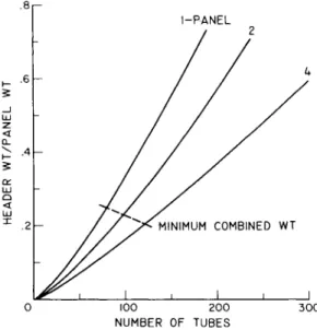
In another weight breakdown, the ratio of the header weights (vapor + liquid) to the panel weight is shown in Fig. 15 plotted against the number of tubes. Pressure drops of 0.05 and 0.02 in the panel and vapor header, respectively, were assumed. For the minimum weight configurations, the headers amount to between 20 and 25$ of the tube panel weight. This ratio is the result of the assumptions made on the liner thicknesses and meteoroid protection requirements. In these calculations the columbium liner accounts for about half the weight of the vapor header. Accordingly, some effort is warranted to see if this liner thickness can be reduced. The figure also illustrates the importance of including header weights in radiator design studies.
Because the header weights are such a large fraction of the radiator weight, a refinement of the pressure drop calculations may be warranted since the header weights are related closely to the allowable pressure drops. Such refinements could in- clude the effect of two-phase flow on the pressure drop in the vapor header, the entrance losses where the vapor header and tubes join, the exit losses at the junction of the tubes and liquid header, and the effect of a tapered liquid header on the pressure drop therein.
In this analysis only the radiator tube panel (fin and tube) was designed for minimum weight. The exposed area used to calculate the armor thickness was the sum of the tube and header areas, and the same armor thickness was used for both tubes and header. If an analysis is derived in which the tubes and headers are treated separately, and different probabilities of no punctures can be assigned to the tubes and headers indi- vidually for the same overall probability, then a lower radi- ator weight may result. It also may be possible to include the header weight in determining the fin dimensions for minimum combined weight of fin, tube, and header.
Conclusions
The results of an analytical study of a finned-tube radiator for a 1-Mw electrical power generating system have indicated that a panel of about 800 ft^ planform area is required. In general, the use of small tubes in the panel reduces the panel weight. However, a large number of tubes is required to keep the pressure drop within the panel down to a usable working value. With the increase in the number of tubes, the vapor and liquid headers become longer and heavier. If the radiator is to employ a single panel, minimum weight is attained with a panel width/length ratio of about 2.5. A weight saving of
about IO56 can be realized by using a four-panel configuration.
With this configuration, the radiator might weigh about 5740 lb using beryllium fins and armor and a columbium liner in the tubes and headers.
The results of this study are very much affected by the assumptions used regarding the meteoroid population and the penetration phenomenon. Because of the large dependence of radiator weight and design on these two factors, greater knowledge in these two fields is required before a definitive radiator design can be made.
Although this study was based on the minimization of the radiator tube panel weight alone, the header weights indicated are sufficiently large that a study in which the entire weight of the radiator (including the headers) was minimized for a given heat rejection seems necessary.
References
1 Moffitt, T. P. and Klag, F. W*, "Analytical investigation of cycle characteristics for advanced turboelectric space power systems/' NASA TN D-472 (October I960),
^ Mackay, D. B., "Powerplant heat cycles for space vehicles,"
Inst. Aerospace Sci. Paper 59-104 (1959).
3 English, R. E., Slone, H. 0., Bernatowicz, D. T«,,
Davison, E. H., and Lieblein, S., T'A 20,000-kilowatt nuclear power supply for manned space vehicles,M NASA Memo. 2-20-59E
(1959).
^ Eward, J. C , "Electric space propulsion," Elec. Eng.
79, pp. 555-562 (July I960).
Coombs, M. G. and Stone, R. A., "SNAP 2 radiative-condenser design," ARS Preprint 1328-60 (September I960).
6 Loeffler, I. J., Lieblein, S., and Clough, N., "Meteoroid pro- tection for space radiators"(published elsewhere in this volume).
Diedrich, J. H. and Lieblein, S., " Materials problems associated with the design of radiators for space powerplants"
(published elsewhere in this volume).
8 Jaffe, L. D., and Rittenhouse, J. B., "Behavior of Materials in Space Environments," Jet Propulsion Laboratory Tech. Report 32-150 ( November 1, 1961).
KREBS, WINCH, A N D LIEBLEIN
9 Haller, H. C , Krebs, R. P., and Bittner, E. C , "Analysis and design procedures for a direct condensing central finned- tube radiator/' NASA TN (to be published).
1 0 Schreiber, L. H., Mitchell, R. P., Gillespie, G. D., and Olcott, T. M., "Techniques for optimization of a finned-tube radiator/' Am* Soc. Mech. Engrs. Paper 61-SA-44 (June 1961).
1 1 Walker, C. L., Smith, C. R., and Gritton, D. G., "Weight optimization of heat rejection systems for space applications,"
Proceedings of 1960 Heat Transfer and Fluid Mechanics Institute (Stanford University Press, Stanford, Calif., 1960\ pp. 244-259.
-^ Lockhart, R. W. and Martinelli, R. C , " Proposed correla- tion of data for isothermal two-phase, two-component flow in pipes," Chem. Eng. Progr. 45^, pp. 39-48 (1949).
13
Denington, R. J., Koestel, A,, Saule, A. V., Shure, L. I., Stevens, G- T., and Taylor, R. B., "Space radiator study,"
Aeronaut. Systems Div. TR 61-697, Contract AF 33(616)-7368 (April 30, 1962).
L FIN
LIQUID OUT %щ
r HEADER
- TUBE
ARMOR
Fig, 1 Finned-tube radiator
.8 1.0 1.2
TUBE INSIDE DIAM, IN. 1.6
Fig. 2 Effect of tube inside diameter on radiator panel specific weight and on the ratio of tube vulnerable area to prime area; AP/P =0.05
KREBS, W I N C H , AND LIEBLEIN
2 . 6 r -
.6 .8 1.0 1.2 1.4 TUBE INSIDE DIAM, IN.
Fig. 3 Effect of tube inside diameter on armor thickness and fin dimensions; Лр/Р =0.05
1.50 125 1.0 0.75 0.625
k \ |\ \
\ \ \ \
\
TUBE DIAM, IN 0.50
\ \
V- \ \°
\% \ % \
\ \ \ \
4MY4\4\\\,
k \ K \ K \ N
\JJ50 100 150 200
NUMBER OF TUBES 250 300
Fig. 4 Relations among number of tubes, tube inside diameter, vapor velocity at tube inlet, and tube pressure drop
.05 .10 .15 .20 .25 TUBE PRESSURE DROP FRACTION, ДР/Р
Fig* 5 Effect of tube pressure drop on tube panel weight
*
r ^ *
SINGLE PANEL
b~
w'—H^ 3 É ^
^ а e ^ :
T
LFOUR PANEL TWO PANEL
Fig* 6 Panel configurations
KREBS, WINCH, AND UEBLEIN
2401—
200 \-
160
GD 0Ć. 120 o
§ 80 a:
40
50 100 150 200
NUMBER OF TUBES 250
TUBE DIAM, IN.
.75
300 1.25
350
Fig. 7 Ratio of tube length to tube diameter for several tube diameters
250,—
200
x i—
Q
_ J LU Z <
Q-
150
100
5 0 h
50
TUBE DIAM, IN.
100 150 200 250
NUMBER OF TUBES 300 350
Fig. 8 Panel width for several tube diameters; single-panel configuration
TUBE DIAM. IN .75 .625
100 150 200 NUMBER OF TUBES
300
Fig. 9 Aspect ratio for several tube inside diameters; single- panel configuration
VV H, FT/SEC 200 300 400 500 600
1.60
100 150 200 N U M B E R OF TUBES
Fig, 10 Effect of vapor header velocity and number of tubes on the vapor and liquid header specific weight; single-panel configuration
KREBS, WINCH, AND UEBLEIN
0 50 100 150 200 250 300 350 NUMBER OF TUBES
Fig. 11 Effect of vapor header velocity and number of tubes on pressure drop in the vapor header; single-panel configuration
0 100 200 300 400 NUMBER OF TUBES
Fig. 12 Vapor and liquid header specific weights for three panel configurations and two pressure drops in the vapor header
100 150 200 NUMBER OF TUBES
Fig. 13 Effect of number of tubes and pressure drop in the vapor header on vapor header diameter for three panel configurations
£ 5.8
WT (AP/P)V
COMBINED 02 COMBINED 05
PANEL
50 100 150 200 250 NUMBER OF TUBES
Fig. 14 Effect of the number of tubes on tube panel specific weight and on combined (panel + headers) radiator specific weight for two pressure drops in the vapor header and three panel configurations; ЛР/Р in the tubes =0.05
KREBS, W I N C H , AND LIEBLEIN
l-PANEL
100 200 NUMBER OF TUBES
300
Fig. 15 Ratio of header (vapor + liquid) weights to tube panel weight for three panel configurations; tube Ap/P = 0.05;
vapor header ДР/Р =0.02