APPLICATION OF BOREHOLE IMAGING METHODS FOR FUTURE DRILLS ON MARS – POSSIBILITIES FOR STRAIN ANALYSIS. A. Boger1 and A Kereszturi2, 1MOL Nyrt H-1117 Budapest, Október huszonharmadika street 13, Hungary, bogeragnes@gmail.com, 2MTA CSFK Konkoly. Astr. Inst., Hungary.
Introduction: This work overviews some possibilities and potential findings using borehole-wall imaging techniques for Mars in the future regarding the local strain fields, based on analogue experiences on the Earth. Because of the surface of Mars is heavily altered by UV plus particle radiations and aggressive oxidants, subsurface drilling is inevitable to sample intact bedrock. First of such drilling activity is planned to be done by the ExoMars 2020 rover of ESA [1]
down to 2 m depth, where although no optical but only infrared imaging is planned by MaMISS [2]. Below future perspectives are described according to the techniques, applicability and potential results for Mars.
Borehole images are electronic pictures of the rocks and fluids of a wellbore, made by electrical, acoustic, or video devices, which have been lowered into the well. Images are oriented, they have high vertical and lateral resolution, and provide critical information about bedding dip, fractures, faults, unconformities, paleocurrent directions, vuggy and fracture porosity, and the borehole shape in general. In this work especially the potential exploitation of paleo- strain field is discussed, comparing three methods:
Electrical borehole imaging uses microresistivity electrodes arranged around the wellbore on pads that are pressed against the wall. Electrical current is forced into the rock through the electrodes, and remote sensors measure the current after as interacts with the formation [3]. On the Earth the drilling mud is the conductive agent, without it measurement can’t work.
Acoustic borehole imaging tools are centralized in the well, a rotating transducer emits and records sound waves which bounce off of the borehole wall. Both acoustic amplitude and travel time are recorded and processed into images. Areal coverage of the borehole face is 100%. Recorded images are compressed helical ultrasonic travel time or amplitude maps of the borehole wall. Colored pixels are arranged in their proper geometric position around the wellbore [3].
Examples are presented in Figure 1, on borehole breakouts (BOs) and drilling-induced tensile fractures (DIFs) interpreted in electrical and acoustic image logs in NSW, Australia. These features occur parallel to the borehole axis and on opposite sides of the wellbore (separated »180°). The width of the BOs is 10-20° and their depth is few centimeters. The BOs are identified as a pair of wellbore elongation zones (low-amplitude zones in acoustic image logs and conductive zones in electrical image logs) and show the orientation of minimum horizontal stress (perpendicular to orientation of SHmax). The DIFs appear as pairs of
narrow conductive features (on resistivity images) or low-amplitude features (on acoustic images) [4].
Figure 1. Earth based example electrical images (left strip pair) and acoustic images (right strip pair) of the borehole breakouts (BOs) and induced tensile fractures (DIFs) [4].
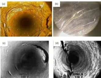
Downhole video tool runs into the hole with a centralizer. The video is seen in real time and recorded at the surface. Borehole coverage is 100%. The tool works in liquid-filled or gas-filled wells, but borehole fluids must be relatively clear. Video images are more widely used in closed-hole studies, although they have important openhole applications [5].
Borehole wall pictures are shown in Figure 2. (a) Bedrock an 8-inch diameter well in Vermont [6]. (b) Closed fractures filled calcite [6]. (c) Damaged zone in the borehole wall. These damages may be caused by drill head/drill bit or a fall-out of the weakened part of the borehole wall [3], (d) Open fractures [3].
Figure 2. Examples of downhole video still shots. (a) intact bedrock. (b) (c) Hole in casing. (d) Open fractures [5].
Application to Mars: On the red planet the following main problems and differences relatively to conditions on the Earth should be accounted for to gain useful results.
● The physical parameters of fractures in fragmented rocks are always different from the continuous
2074.pdf 50th Lunar and Planetary Science Conference 2019 (LPI Contrib. No. 2132)
bedrock regarding of the type of filling (gas, liquid or solid), therefore these are usually visible on the borehole images.
● No liquid filled pores are expected on Mars. If the open fractures are filled with gas the pores show large resistivity which is comparable to resistivity of the bedrock therefore can’t be detected with electric borehole imaging method. At the same time these fractures shows lower acoustic amplitude and bigger travel time than the basaltic rocks therefore they are visible on the acoustic borehole images. It means that fracture density could be well estimated using these techniques. If the pores are filled with highly saline water (what is realistic because of the potential appearance of microscopic brine films) the fractures can be detected by these techniques in the Earth.
● The low temperature in general causes technical problems that should be overcome by the technical development of specific electronics.
● Ice filled fractures show lower amplitude on the acoustic borehole images. The amplitude of the acoustic waves are very sensitive to the structure of the rocks, and the mineral consistence. On the acoustic images the ice filled fractures are visible lower acoustic amplitude while the intact bedrock is larger acoustic amplitudes.
● The separation of different rock types on the borehole wall pictures is not possible, requires additional carotage measurements such as natural gamma and density logging.
The strain state of the Martian crust is poorly known, despite wide range of surface features (faults, folds, caldera shapes) point to the existence of global and regional stress fields, which could influence borehole features in the almost continuous bedrock, while in the upper and fragmented regolith layer the annual H2O uptake / desiccation could produce stress.
The inhomogeneous spatial distribution of fractures and borehole cross section shape on Mars could point to existing stresses there, what might be related to oriented stress field that were probably produced long time ago by global contraction and could survive long time in the inactive environment of Mars.
Permafrost drilling on Earth would give important experiences that are relevant for Mars, however only a few drillings have been realized there, thus acoustic or electrical borehole wall images are not available there. Although there are core samples some examples are visible in Fig. 3. Ground ice occurs in two main forms, as structure-forming ice, bonding the enclosing sediments, and as large bodies of more or less pure ice. The structure-forming ice comprises segregated ice, intrusive ice, reticulate vein ice, ice crystals, and icy coatings on soil particles. The large bodies of more or less pure ice, which exist mainly in
the upper part of the ground. We would see similar core samples in the planned Mars drilling.
Figure 3. Earth based examples of permafrost core sam- ples. (a) and (b) Permafrost core samples in Siberia [6,7,8].
Conclusions: Earth based field and laboratory examples demonstrate that the borehole wall deformation induced by the rock stress (BOs, DIFs) are visible on the acoustic and electrical borehole images.
These are lower resistivity zones on the electrical borehole images and caused by the larger travel time, or lower acoustic amplitude. Conditions prevailing in the Mars the electric method will not give definite results therefore the acoustic borehole imaging technique is recommended. The direction of the borehole wall deformations is refer to stress field on the Mars are expected to be identified in the form of at least two types:
1. With similar directions in nearby boreholes from regional scale stress fields, mainly by global contraction or volcanic/magmatic loading, reflecting quite old but strong stress fields. 2. Small scale local fields from ice content change related stress, showing variable orientation distributions in nearby boreholes, mainly in regolith, reflecting recently produced weak stress fields. The possibility of borehole imaging based stress analysis for Mars should be taken as a potential field to explore during future drilling on Mars.
Acknowledgement: The Mars relevant aspects of were supported by the EXODRILTECH project of ESA, the instrument and technical aspects by the GINOP-2.3.2-15-2016-00003 project of NKFIH.
References: [1] Vago J. et al. (2017) Astrobio. 17, 471-510. [2] DeSanctis M.C. (2017) Plan. Space Sci.
17, 612-620. [3] Neil H. (2004) AAPG Meth. in Expl.
16, 151–163. [4] Rajabi M. et al. (2016) Austral. J Earth Sci. 63(1):1-21. [5] Homepage of the Allegheny Instruments, Inc. [6] Natali S. Woods Hole Research Center. [7] University of Alaska Fairbanks, Harms Lab. [8] Database of the Canadian Permafrost Monitoring Network.
2074.pdf 50th Lunar and Planetary Science Conference 2019 (LPI Contrib. No. 2132)
![Figure 3. Earth based examples of permafrost core sam- sam-ples. (a) and (b) Permafrost core samples in Siberia [6,7,8]](https://thumb-eu.123doks.com/thumbv2/9dokorg/1069995.71228/2.918.480.807.146.409/figure-earth-based-examples-permafrost-permafrost-samples-siberia.webp)
