IOP Conference Series: Materials Science and Engineering
PAPER • OPEN ACCESS
Comprehensive analysis of local corrosion degradation on austenitic pipeline
To cite this article: P Trampus et al 2018 IOP Conf. Ser.: Mater. Sci. Eng. 426 012050
View the article online for updates and enhancements.
This content was downloaded from IP address 152.66.35.17 on 29/01/2019 at 08:38
1234567890‘’“”
11th Hungarian Conference on Materials Science IOP Publishing
IOP Conf. Series: Materials Science and Engineering 426 (2018) 012050 doi:10.1088/1757-899X/426/1/012050
Comprehensive analysis of local corrosion degradation on austenitic pipeline
P Trampus1, J Dobránszky2, Z Kerner3, J Knisz4, F Oszvald5, B Palotás6, L Péter7, M Réger8 and B Verő9
1 Research professor, University of Dunaújváros, Dunaújváros, Hungary
2 Scientific advisor, Research Group for Composite Science and Technology, Budapest, Hungary
3 Senior researcher, Centre for Energy Research, Hungarian Academy of Sciences, Budapest, Hungary
4Research scientist,VEIKI Energia+ Ltd, Budapest, Hungary
5 Consultant, Oszvaldfer, Paks, Hungary
6 Associate professor, University of Dunaújváros, Dunaújváros, Hungary
7 Scientific advisor, Wigner Research Centre for Physics, Hungarian Academy of Sciences, Budapest, Hungary
8 Full professor, Óbuda University, Budapest, Hungary
9 Professor emeritus, University of Dunaújváros, Dunaújváros, Hungary E-mail: trampus@uniduna.hu
Abstract. Corrosion degradation was observed in a nuclear power plant spent fuel cooling system. A systematic and comprehensive investigation program was developed to reveal the root cause of the degradation. Series of corrosion tests, mechanical, microstructural and microbiological investigations were carried out. Also, simulations of the operating conditions and welding parameters were performed. Based on the results, the major contributors to the degradation process were identified and a possible degradation mechanism was proposed.
1. Introduction
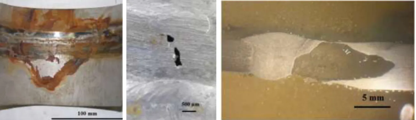
After 26 operating years, leakage was observed in the spent fuel pool cooling system at the Paks Nuclear Power Plant, Hungary. The cooling medium is boric acid with a concentration of > 14.5 g∙dm-3; and average temperature of ~30°C. Two parallel loops operate alternately. Results of the immediate non- destructive examinations and subsequent comprehensive investigations made it clear that the leakage was caused by pitting corrosion on the inner surface of the cooling system pipelines. Some of the pits penetrated through the whole wall thickness. The structural material of the pipelines is Cr-Ni-alloyed, Ti-stabilized austenitic stainless steel (08Ch18N10T, nearly equivalent with steel 1.4541). The diameters vary from 100 to 300 mm; the wall thickness range is 6 to 10 mm. The pipes were laid down in concrete which made their investigations and subsequent replacements difficult and time consuming.
Figure 1 shows a through-wall pit detected by visual inspection and ultrasonic examination as well (left:
corrosion products around a circumferential weld; middle: two pits after cleaning and decontamination;
2
1234567890‘’“”
11th Hungarian Conference on Materials Science IOP Publishing
IOP Conf. Series: Materials Science and Engineering 426 (2018) 012050 doi:10.1088/1757-899X/426/1/012050
The plant operator asked technical support organizations to perform a root cause analysis of this service-induced, unexpected degradation phenomenon developed after quite a long operation period.
The complexity of the question required knowledge from various technical areas such as material science, electrochemistry and corrosion science including microbiologically induced corrosion (MIC), welding technology and plant operation. The working team was composed of representatives of leading academic institutes and universities to complete the task. The description of the degradation phenomenon as well as the investigation process and analyses (Phase I – 2013-2014) were described previously [1]. The goal of the present paper is to summarize the results focusing primarily on those which were achieved following the first stage (Phase II of investigations – 2016-2017), and to suggest the most likely degradation mechanism.
Figure 1. Pitting corrosion around the welded joint – pipe: Ø 219x10 mm (left: as is, middle: after cleaning, right: cross-section with the inside down)
2. Previous investigations
During Phase I samples were taken out from the leaking pipeline system, and the following characteristics were determined:
long term corrosion potential, corrosion rate, electrochemical impedance, pitting potential (provoked by chloride ions and ferric chloride);
bulk and local chemical composition (energy-dispersive X-ray spectroscopy – EDX, laser ablation inductively coupled plasma mass spectrometry – LA-ICP-MS), deposit composition;
mechanical properties;
microstructures (optical microscopy – OM, scanning electron microscopy – SEM, electron backscatter diffraction – EBSD);
microbial presence (fluorescence microscopy, culture methods).
The electrochemical investigations were repeated on archive material and on identical new material as well.
The results [1] of these investigations showed that the corrosion resistance, chemical composition, mechanical properties and features of non-metallic inclusions were all in compliance with the relevant standard values. Most of the inner surface of the pipeline system was intact, conditions for the corrosion occurred locally. The majority of the corrosion was associated with heat tint covering the heat affected zone (HAZ) of site welds. Also, evidence of the presence of organic material on the corrosion surface was found, giving rise to suspicion of MIC process.
Obviously, more than one element of the entire system contributed to the corrosion. Major contributors include the oxide layer on the HAZ and associated corrosion sensitivity nearby welds, microbiological effects, and operating conditions such as flow velocity, stagnation and temperature ideal for microbial growth.
1234567890‘’“”
11th Hungarian Conference on Materials Science IOP Publishing
IOP Conf. Series: Materials Science and Engineering 426 (2018) 012050 doi:10.1088/1757-899X/426/1/012050
3. Current investigations and analyses
In Phase II complementary investigations, analyses, and modelling/simulation were performed. Also, the results of MIC monitoring started after completing Phase I were incorporated and evaluated.
3.1. Root cause investigations
The following investigations served for identifying the root cause of the localized corrosion degradation on the piping system of the spent fuel pool.
3.1.1. Effect of microbes on the corrosion phenomena. Over a two-year period, we were monitoring biomass changes in the bulk medium and found that most of the time the biomass was in the range of 102-103 ME∙mL-1, sometimes increasing up to 104 ME∙mL-1 (ME = microbial equivalent, cells). Next generation sequencing of the bulk medium revealed that the majority of the microbes is Ralstonia pickettii, a mixotrophic species viable in ultrapure water [2, 3]. It can live in an autotrophic manner by using only H2 as a sole source of energy and CO2 as the sole carbon source. It is known to produce extracellular polymer material, a matrix needed for biofilm development. The sequencing revealed members of the Desulfobacteriaceae and Desulfovibrionaceae family, members of the Burkholderia family, the Sediminbacterium genus that have been implicated in iron oxidation [4], as well as the acid producing Acinetobacter genus [5] that has been shown to be a pioneer bacterium in biofilm development [6, 7]. Although the amount or the type of microbes present in the bulk fluid does not represent microbes on the surface, the results suggest that Ralstonia pickettii together with other Ralstonia species might initiate biofilm development in the presence of boric acid. Biological activity reaction test (BART) [8] performed on corrosion products collected from the bottom of the pipes revealed the presence of both iron oxidizing and iron reducing bacteria, heterotrophic micro-organisms, slime forming bacteria, as well as acid producing bacteria. Sulfate reducing bacteria were not detected.
Corroded areas were analyzed by fluorescence staining to visualize live and dead cells inside the pit after cleaning (Figure 2C) and on corrosion deposit (Figure 2A).
4
1234567890‘’“”
11th Hungarian Conference on Materials Science IOP Publishing
IOP Conf. Series: Materials Science and Engineering 426 (2018) 012050 doi:10.1088/1757-899X/426/1/012050
Figure 2. Fluorescence staining of corroded stainless steel.
A. Live cells (upper) and merged image (lower) of corrosion products; B. The corroded surface; C.
(1) bright field image, (2) live cells, (3) dead cells, (4) merged image
The pit had a shiny metallic surface (Figure 2B: lower picture) suggesting an active corrosion mechanism, and live/dead stain revealed microbes inside the pit but not outside (Figure 2C).
A SEM/EDX analysis at another corrosion site revealed phosphorus, sulfur and carbon that may be indicative of microbial presence at the site of corrosion. Left picture (SEM) in Figure 3 shows the pit and the porous corrosion product around it; on the right side the EDX spectrum can be seen.
1234567890‘’“”
11th Hungarian Conference on Materials Science IOP Publishing
IOP Conf. Series: Materials Science and Engineering 426 (2018) 012050 doi:10.1088/1757-899X/426/1/012050
Figure 3. Porous corrosion product (inset) and its EDX-spectrum
3.1.2. Oxide layer. Both the literature and the results of our investigations suggested that the oxide layer appearing as heat tint, i.e. welding scale on some pipes plays leading role in the development of the corrosion process. In order to better understand as well as to validate the literature data with factual findings, we analyzed the main features of the oxide layer’s composition and structure on samples prepared for modelling the oxide layer.
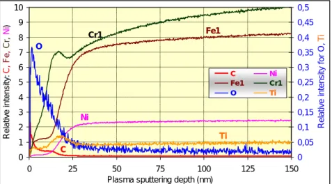
The glow discharge optical emission spectroscopy (GD-OES) is capable of measuring the layer’s thickness and determining its tentative chemical composition. In Figure 4 the GD-OES intensity measured on the transition to HAZ can be seen. First of all, the oxygen content and the distribution of Ni, which has a low inclination to migrate can indicate the boarder of the oxide layer with the thickness being approximately 10 nm. In the middle of the HAZ the thickness approaches 50 nm while on the normal surfaces the passive layer thickness does not exceed 3-4 nm. Intensity of Fe, Cr and Ni
Figure 4. GD-OES intensity of various elements as a function of the sputtering depth, on clean surface
C Ni
Cr1 Fe1 O
Ti 0
1 2 3 4 5 6 7 8 9 10
0 25 50 75 100 125 150
Plasma sputtering depth (nm)
Relative intensity:C,Fe, Cr,Ni)
0 0,05 0,1 0,15 0,2 0,25 0,3 0,35 0,4 0,45 0,5
Relative intensity for O, Ti
C Ni
Fe1 Cr1
O Ti
6
1234567890‘’“”
11th Hungarian Conference on Materials Science IOP Publishing
IOP Conf. Series: Materials Science and Engineering 426 (2018) 012050 doi:10.1088/1757-899X/426/1/012050
and has a less beneficial Cr-oxide/Cr and Cr/Fe ratio. On the other hand, during the evolution of the thicker oxide layer more Cr will be detracted from the area beneath the scale than in the case of a normal passive layer.
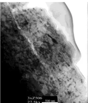
Similar oxide layer thickness could be identified by transmission electron microscopy (TEM). On a segment perpendicular to the surface, the glue indicates the outer surface of the sample, see Figure 5, and immediately under it an amorphous oxide layer is visible with a thickness of 50–100 nm.
Figure 5. TEM picture of the welding scale covered thin foil 3.2. Records of visual inspections of the pipeline’s inner surface
The video records made by professional inspection vendors between 2013 and 2017 were analyzed and evaluated. The following conclusions were drawn:
Considering purely the number of degraded spots, ~60 % are located on or near welded joints. As the total surface of the welds represents only a small fraction of the entire surface of the piping system, vulnerability of welds to corrosion exceeds that of flat pipe surfaces by several orders of magnitude.
The area covered by corrosion products spreads out in 80–90 % on welds, i.e. on root bead, HAZ and a band of parent material directly next to HAZ with heat tint. The remaining portion of corroded area could be identified on the base material of the pipes. Corrosion was mainly observed in the flow direction following the welds.
There seems to be a clear, though not exclusive, relationship between corrosion of welds and that of other surfaces. The pitting corrosion can start in both welds and flat surfaces in areas covered by sediment delivered by the cooling medium degrading the passive layer, as well as in areas where the microbiological effect is more pronounced.
3.3. Simulations and analyses
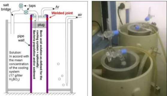
3.3.1. Integrated modelling. A demonstration experiment to study the collective effect of each factor contributing to the corrosion phenomenon was performed. These factors are the following: differential aeration, welding without root protection, corrosion sediment, presence of microbes and chloride ions.
Experimental parameters demonstrated extreme values for corrosion. The medium was much more aggressive than in the spent fuel pool resulting substantially accelerate the corrosion process. The
1234567890‘’“”
11th Hungarian Conference on Materials Science IOP Publishing
IOP Conf. Series: Materials Science and Engineering 426 (2018) 012050 doi:10.1088/1757-899X/426/1/012050
experimental setup is shown on the left side of Figure 6, the equipment used for the experiment is shown on its right. The following were concluded:
Long term operation (46 days) of differential aeration cells with large cathode/anode surface ratio confirmed the extreme corrosion sensitivity of weld produced without proper protection. These samples showed approximately ten times faster corrosion velocity than the samples without welds.
Also, simulation of differential aeration in anaerobe environment revealed biofilm development on surfaces of solid materials. It occurred even in the presence of boric acid. A biofilm is considered as a potential initiation factor for microbiological corrosion degradation.
On the weld root side of the specimens, the initiation stage of pitting corrosion could be observed, as well as indications for tuberculum development were found. It is to be emphasized that these degradation processes developed in a relatively short time.
Figure 6. Setup of the differential aeration model (left) and the equipment (right)
3.3.2. Impact of welding parameters. Welding experiments were performed following the original WPS (Welding Procedure Specification); the following parameters were varied:
Deviation from WPS Without root protection
With imperfect root protection
Parent materials were not prepared except edge preparation Heat input limit was exceeded
Heat input limit was exceeded, and with imperfect root With significantly enlarged root gap
Root protection only by root welding
The inner surfaces of the samples cut out from the welded joints were investigated by SEM; the chemical composition of the pipe in the vicinity of the joints was also analyzed. The pitting corrosion sensitivity was investigated using the ASTM G48 standard [9]. The tests were performed in two solutions with different concentration of FeCl3 (3.6 % and 6 %) at two different temperatures (room-
8
1234567890‘’“”
11th Hungarian Conference on Materials Science IOP Publishing
IOP Conf. Series: Materials Science and Engineering 426 (2018) 012050 doi:10.1088/1757-899X/426/1/012050
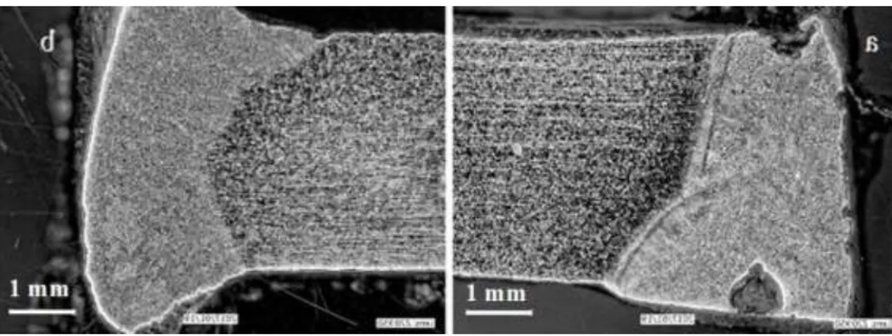
intensive degradation supports the hypothesis that root protection has significant impact on the corrosion sensitivity of the welds. Figure 7 shows the sample welded in accordance with WPS but without root protection. Pits can be seen both on the weld face and at the root in the sample tested at 50°C. The latter demonstrates the influence of the temperature. Significantly more corrosion products were formed when the solution contained MIC bacteria compared to a non-MIC environment.
Figure 7. Test at 50°C, in 3.6 % FeCl3 (a); at room-temperature, in 6 % FeCl3 (b)
3.3.3. Gamma irradiation. The effect of the gamma irradiation on microbes associated with MIC was investigated to estimate their viability. A radiological test environment simulating the spent fuel pool was developed. Based on the results a dose of 100 kGy kills the majority of the microbes irradiated, but the solutions’ sterility can only be achieved if the concentration of the microbes does not exceed an order of magnitude of 107 ME∙mL-1. It is likely that in the spent fuel pool, close to the fuel assemblies, the majority of microbes perishes within a few hours. However, due to the periodic flow of the cooling medium among the assemblies, gamma irradiation is insufficient to sterilize the medium, thus microbes can reach distant surfaces of the cooling system where the dose rate is low.
4. Evaluation of the results, conclusions
Evaluating all results including those achieved at the end of Phase I, the following uniform statements and conclusions can be given. From a corrosion’s point of view, the spent fuel cooling system is considered as a complex and open system. Its corrosion behavior is determined by many contributing factors as well as by their interaction. The specific effect and the relative weight of the individual factors may vary and the observed localized pitting corrosion degradation cannot originate from a single, well defined factor or root cause.
The typical and average chloride ion concentration and boric acid content of the cooling medium applied either alone or in combination with other factors cannot initiate this corrosion process. The structural material of the pipes meets the standard requirements.
On significant number of the welds produced in the field, on the pipes’ inside surface an undesired oxide layer (heat tint, weld scale) is present. The composition profile of these surfaces and the area beneath deviates from that providing the proper passive condition; thus, the corrosion resistance of the surface range is reduced as a consequence of the thermal process.
In the cooling medium with the typical boric acid content, various micro-organisms can grow; and several micro-organisms previously associated with MIC were identified. An optimal temperature for reproduction of micro-organisms is 15–40°C, which corresponds to the cooling system’s operation temperature range. Depending on both the medium composition and operating conditions (periodic operation, stagnation) the thermal oxide layer around the welds, i.e. the weld scale fosters the attachment of micro-organisms leading to MIC. The development of biofilms induces a local reduction in oxygen supply of the area and lead to the creation of local aeration cells. Reactions within the biofilm are usually
1234567890‘’“”
11th Hungarian Conference on Materials Science IOP Publishing
IOP Conf. Series: Materials Science and Engineering 426 (2018) 012050 doi:10.1088/1757-899X/426/1/012050
localized and influence electrochemical processes, typically accelerate them and subsequently result in localized corrosion.
5. A possible degradation process
Iron-oxidizing bacteria obtain their energy by oxidizing Fe2+ ion to Fe3+ ion. Due to this activity of the bacteria an orange-red color, cave-like iron-oxide sediment (tubercle) formed. The iron-oxide sediment blocks the oxygen and provides the right environment for iron reducing bacteria. Subsequently, this anoxic area will act as an anode compared to the surrounding oxygen-rich cathode. At the anode area, the oxidation of the metal takes place, which leads, through the hydrolysis of the newly produced metal ion, to the decrease in pH. These processes with the lack of oxygen as re-passivation agent subsequently lead to the acceleration of corrosion.
In the porous structure of the tubercles, due to local effects, the chloride-ion content of the cooling medium may locally increase. Taking into consideration the limited flow inside the biofilm, an anoxic and chloride-ion rich medium can develop strengthening the local cell effect quite dominantly. During medium flow, the corrosion product can be separated from the surface and be drifted towards the flow, some of these products may adhere to other surfaces in the system. The separated product can contain iron hydroxide as well as living and dead micro-organisms originating from the tubercles.
6. Summary
A local corrosion degradation phenomenon was identified after a long operation time in a nuclear power plant system. A comprehensive investigation program was developed to invent the root cause of the degradation. The program included various corrosion tests, mechanical, microstructural, and microbiological investigations and simulations of the operating conditions and welding parameters.
Based on the evaluation of the results of the investigations and analyses, the major contributors to the corrosion degradation were identified. These were identified as being the oxide layer on the HAZ of the welds and associated corrosion sensitivity nearby, the effect of micro-organisms, and operating conditions such as flow velocity, stagnation and low temperature.
Acknowledgements
The authors would like to express their gratitude to G Radnóczy for the TEM investigations and to T Török for the GD-OES analyses.
References
[1] Trampus P et al 2017 Investigation of local corrosion degradation developed on a pipeline system in service period Materials Science Forum 885 92
[2] Adley C C et al 2005 Ralstonia pickettii: biofilm formation in high purity water The Biofilm Club 151
[3] Gales G et al 2004 Action of an aerobic hydrogenotroph bacteria isolated from ultrapure water systems on AISI 304 stainless steel Proc. Int. Conf. EUROCORR 2004 (Nice) 11
[4] Kuever J 2014 The Prokaryotes Chapter: The family of Burkholderiaceae Springer 759
[5] Pavissich J P 2010 Culture dependent and independent analyses of bacterial communities involved in copper plumbing corrosion Journal of Applied Microbiology 109 771
[6] Wang H B et al 2012 Effects of disinfectant and biofilm on the corrosion of cast iron pipes in a reclaimed water distribution system Water Res 46 1070
[7] Percival S J 1999 The effect of molybdenum on biofilm development Ind Microbiol Biotech 23 112
[8] http://www.dbi.ca/StandMeth/ {checked at December 12, 2017}
[9] ASTM G48 - 11 2015 Standard Test Methods for Pitting and Crevice Corrosion Resistance of Stainless Steels and Related Alloys by Use of Ferric Chloride Solution, ASTM International,