Easy-to Use Function Generator Applying PIC
P. Kiss, Gy. Györök and T. Orosz Obuda University/AREK, Székesfehérvár, Hungary
pkiss90@gmail.com, gyorok.gyorgy@arek.uni-obuda.hu, orosz.tamas@arek.uni-obuda.hu
Abstract—Function generators have been widely used in electrical measurements. Several manufacturer firms distribute measuring equipment. They are usually expensive and should be adjusted to other devices and software elements. This paper discusses an approach to create an easy-to-use function generator applying PIC.
I. INTRODUCTION
My goal is to convince people that anyone can create a function generator easily, applying a microcontroller.
My system is based on PIC16F887 because its price and it is used worldwide.
I started to develop this hardware due to high prices of signal generators and I thought I can do it on my own.
Function Generator
Function generators are similar to oscillators. It provides alternate currents with adjustable frequency, amplitude, waveform and duty cycle.
It is suitable testing ideal amplifiers, active or passive filters or determines speakers operation.
We can use it testing panels as primary clock source too [1].
“Function generators are used where stable and repeatable stimulus signals are needed. Here are some common uses and users:
Research and development Educational institutions
Electronic and electrical equipment repair businesses
Stimulus/response testing, frequency response characterization, and in-circuit signal injection Electronic hobbyists”
In the first place I wanted to create a hardware that is capable creating three kinds of waveforms with adjustable frequency.
I decided to create sine, square, and triangular waves [2].
“Sine wave: A function generator will normally have the capability to produce a standard sine wave output.
Square wave: A square wave is normally relatively easy for a function generator to produce. It consists of a signal moving directly between high and low levels.
Triangular wave: This form of signal produced by the function generator linearly moves between a high and low point.”
II. SCHEME
Fig. 1
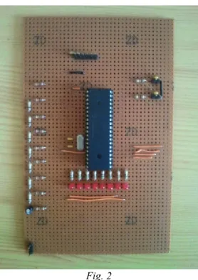
Fig. 2 Fig 1. shows the scheme of my board.
After designing I have built the real hardware that Fig 2.
represents.
It consists of just a couple of parts.
On Fig 2. it is visible that there are six pins at the bottom. These are the programmer pins.
On the right-side there are four pins for push-buttons.
In the middle there is a microcontroller, under it there are eight leds for testing, to the left there is an R/2R voltage divider and under it there are 2 pins for the appropriate sign.
III. HARDWARE AND SOFTWARE
In order to implement this device first I started to develop the software.
I choose FlowCode, because it has a very developer friendly environment with great built-in simulator, helpful and skilled programmers [3].
“Flowcode is one of the world‟s most advanced graphical programming languages for microcontrollers.
Flowcode is available in more than twenty languages and currently supports the PICmicro, dsPIC, PIC24, AVR and ARM series of microcontrollers.”
With this software people can program target objects with flowcharts.
Of course it is possible to use .asm or .c files if it is necessary.
This program has lots of advantages and only some disadvantages.
Advantages:
User-friendly Easy-to use
Quick developments Built-in simulator
Skilled programmers on its forum Disadvantages:
Larger programs in PIC‟s memory Expensive
Fortunately program‟s size cannot be a problem because today‟s microcontrollers have enough memory.
Fig. 3, 4, 5 represent my program‟s flowchart.
It has three parts: a Main, a TIMER and an RB0 section.
Fig. 3
Fig. 3 starts with a C code, because I want to set all PORTC as output. Then two interrupts are followed.
If someone pushes the first push-button than RB0 interrupt will happen.
This is the function selector.
Without a press on the output there will be a sine wave.
After pressing this push-button there will be a square wave and with another press inflict triangular wave on the output.
If somebody pushes the second push-button than TIMER0 interrupt will happen.
It will decrease the sign‟s period of time, therefore frequency will be higher.
Fig. 4 and Fig. 5 show its method.
Fig. 4
Fig. 5
In order to keep different signs frequencies equal, I used three same element Lookup-tables (LUT) [4].
“In computer science, a lookup table is a data structure, usually an array or associative array, often used to replace a runtime computation with a simpler array indexing operation. The saving in terms of processing time can be significant, since retrieving a value from memory is often faster than undergoing an „expensive‟ computation or input/output operation.
The tables may be precalculated and stored in static program storage, calculated as part of a programs initialization phase, or even stored in hardware in application-specific platforms. Lookup tables are also used extensively to validate input values by matching against a list of valid items in an array and, in some programming languages, may include pointer function to process the matching input.”
So I created three 32-elements LUTs, for sine, square and triangular.
Here is the source code how I used LUTs.
But it is just three 8-elements to demonstrate how it works.
rom char* Sinus=
{ 131, 220, 255,
{ 255, 255, 255, 255, 0, 0, 0, 0 };
rom char* Trian=
{ 128, 192, 255, 191, 127, 63, 0, 64 };
Fig. 6, 7, 8 are created by Excel to demonstrate how these signs seemed.
Sine wave:
0 50 100 150 200 250 300
1 3 5 7 9 11 13 15 17 19 21 23 25 27 29 31
Fig. 6
50 100 150 200 250 300
0 50 100 150 200 250 300
1 3 5 7 9 11 13 15 17 19 21 23 25 27 29 31
Fig. 8
After development I could test my software in Real Pic simulator before I built the hardware.
In my opinion it is a useful program if someone wants to test programs before building it.
It was an important step because unfortunately Flowcode cannot simulate C and ASM codes.
It showed that the highest frequency is about 1388,89Hz as it is viewed on Fig. 9
Fig. 10 shows the measurements on the real hardware.
Fig. 9 1/(1,2*600*10-6)= 1388,89Hz
Fig. 10
The lowest frequency is about 1Hz as Fig. 11, 12 shows.
1s=1Hz
Fig. 11
Fig. 12 Fig. 13: Sine wave
Fig. 14: Triangular wave
Fig. 13
Fig 14
IV. OUTPUT OF DEVICE Ref. [5]
“Digital-to-Analog Conversion
When data is in binary form, the 0‟s and 1‟s may be of several forms such as the TTL form where the logic zero may be a value up to 0.8 volt and the 1 may be a voltage from 2 to 5 volts. The data can be converted to clean digital form using gates which are designed to be on or off depending on the value of the incoming signal. Data in clean binary digital form can be converted to an analog form by using a summing amplifier.
R-2R Ladder DAC
The summing amplifier with the R-2R ladder of resistances shown produces the output
where the D‟s take the value 0 or 1. The digital inputs could be TTL voltages which close the switches on a logical 1 and leave it grounded for logical 0. This is illustrated for 4 bits, but can be extended to any number with just the resistance values R and 2R (Fig. 15)”
Fig. 15
With an 8 bit R-2R it is possible to achieve 256 different values (Fig. 16).
Fig. 16
First R-2R value on PORTC: 11111111 Second value on PORTC: 10000000
And last one: 00000011
The program sends 0-255 binary value to PORTC then every pin is connected to a resistor.
Corresponding to the value it will be a correct voltage in the output and signs will be created from data.
The hex file that was created by Flowcode was imported in Pickit 2 Programmer.
Then it was needful to configure the configuration bits because program uses as default.
V. PROBLEMS SOLUTION
It is much lower than with DAC in a same way. I want to use a potentiometer to set the frequency. But I found it out if I use a push-button it can increase the speed.
In my opinion a given kind of display is beneficial to show how much the frequency is and what kind of waveform it is.
A relevant thing is the speed; therefore I did not build it in the system.
LUT‟s: now in the program there are three 32 steps LUT‟s but if three 8 steps would be used then frequency will be much higher.
Unfortunately frequency and accuracy are opposite of each other, so with 8 steps sine would not be so correct.
Another advantage of using an ADC that it does not need to use three kinds of output:
Sine: Low Pass Filter Triangular: Capacitor/- Square: -
After I have built the hardware a problem was found with the push-button on RB0.
When we push it, the hardware is breaking down.
I do not understand what could be the problem.
Therefore I was in connect in hobbielektronika‟s [6]
and Flowcode‟s forums through the Internet [7].
People were really helpful and tried to find out why it is occurring?
Then there was a good idea to put two 100nF capacitor parallel with push-buttons to avoid bounces.
After that my system works properly.
VI. OPPORTUNITIES FOR FURTHER DEVELOPMENTS I had some ideas in connection with the hardware development.
Instead of using a 20MHz clock a microcontroller that can work in 64MHz could be better to achieve higher frequencies in the range of 1-20000Hz.
It is possible to increase frequency with decrease steps in LUT. In higher frequencies it is not visible; therefore it can be solved by sectioning the parts.
Higher frequencies are made out from fewer steps then lower frequencies.
Instead of using leds showing periods of time, it would be better to use another PIC to measure the frequency of sign and visualize it on an LCD display.
REFERENCES
[1] Don Peterson & B&K Precision Corporation: Function Generator