Determinations of Position in the Local Reference System
1 HE immediate angular measurements that are made in astrometric observations, and their relation to the coordinates of the object and of the observer in the local reference system, depend upon the particular instru- ments and methods of observation which are used. The angles which are directly obtained from the readings of the graduated circles of an instrument represent the position of the observed object relative to fiducial points determined by visible reference marks. For example, in determining altitude with a marine sextant, the angle directly measured by observation is the angular distance from the visible horizon. To obtain the altitude in the horizon coordinate system, corrections must be determined for the departures of this visible reference line from the abstract geometric circle that defines the astronomical horizon. However, concrete representations of the astronomical vertical by the plumb line, or of the plane of the astronomical horizon by an undisturbed liquid surface, may be incorporated in various different forms into instruments by means of which fiducial points that represent the directions to the zenith and the horizon may be determined, and with which the zenith distance or the altitude of an object may therefore be measured directly.
For example, with a theodolite or a bubble sextant, the altitude referred to the astronomical horizon is obtained directly from the circle reading.
In order to measure azimuths, the meridian must be determined, which requires the location of the celestial pole in addition to the zenith. No method is available by which the position of the pole can be immediately observed; but in practice, an adopted meridian line, determined by observing the diurnal motions of circumpolar stars and tangibly marked by mires, may be used.
By these means, a celestial object, or any visible reference system on the rotating celestial sphere such as a set of comparison stars, may be referred to the local horizon coordinate system. Through this intermediary, observa- tions may be referred to the coordinate systems on the rotating sphere by means of the geometric relations of these systems to the local reference system developed in Chapter 3. Conversely, since these relations depend explicitly upon the geographic coordinates, they are a means by which
204
geographic positions may be determined from astronomical observations, and they are the basis of the practical methods used in surveying and navigation.
The Reduction of Observations in the Horizon Coordinate System In addition to corrections depending on the type of the instruments and the methods of observation, further corrections to the direct instrumental readings may be necessary for refraction and other circumstances of observa- tion, and for the variations of the coordinate systems, according to the purpose of the observations.
The point on the celestial sphere at which an object is perceived, as viewed through the atmosphere from a particular geographic location on the rotating surface of the moving Earth, is displaced by refraction and aberration from the geometric projection of the body upon the sphere; and if the geocentric parallax is appreciable, it depends upon the geographic location of the observer. In observational astronomy and its practical applications it is the established practice to reduce observed positions, corrected for refraction, to the center of the Earth by applying corrections to eliminate the displacements due to geocentric parallax and diurnal aberration. Likewise, ephemerides, where obviously it would be impracticable to provide for the circum- stances of every observation for which they may be used, are in general geocentric. The observed position in the horizon system, and the derived position in the coordinate systems on the rotating sphere, are referred to the instantaneous reference systems on the celestial sphere and on the surface of the Earth as determined by the direction of the axis of rotation in space and its position within the Earth at the time of observation.
Furthermore, astronomical observations, like all physical measurements, are inevitably affected by errors of observation, partly systematic and partly of a random accidental character, due to imperfections of construction and adjustment of the instruments, external disturbances, personal equation of the observer, and other causes. The immediate readings of the instrument must be corrected for these errors as well as possible, before using the readings to obtain the coordinates of the observed object.
The correction of the observations, the determination of the coordinates in a particular reference system from the directly observed angles, and the transformation to other reference systems collectively constitute the reduction of the observations.
Reductions for Semidiameter
Special reductions are sometimes required for individual celestial bodies, particularly bodies which have an appreciable disk. The position of the
object is represented by the coordinates of the center of the disk; but the center cannot be directly observed with accuracy, and in practice its position must be derived by observing points on the limb and correcting these observa- tions by the amount of the semidiameter. The geometric semidiameter depends upon the parallax, but the apparent size of the disk also depends upon optical effects such as irradiation. Moreover, the visible disk may differ from a circle because of the oblate form of the body, defective illumina- tion due to phase, or distortions of the disk by refraction. In the case of the Moon, the limb is very irregular because of the lunar topography.
In general, differential formulas may be used to advantage in obtaining the required corrections. For example, to determine by observation the time at which the center of the disk transits the meridian, the observed time of transit of the limb must be corrected by the interval of time required for the semidiameter to cross the meridian. At any instant, the hour angle ΔΑ subtended by the semidiameter S is the difference Δα of the right ascensions of the center and the point on the limb at the same declination; Δα is the angle at the pole between the hour circles through this point and the center, and since it is small, we have A 0 „
Δα = S sec o.
When the center of the disk is on the meridian at declination ô and right ascension a, and the sidereal time is therefore Θ = a, the hour angle ΔΑ of either limb is Δα = ac — OLL, negative for the east limb, positive for the west limb. The rate at which the center describes this hour angle is ddjdt — doLJdt, where Θ denotes the hour angle of the equinox. Therefore the interval T of sidereal time required for the semidiameter to cross the meridian after the transit of the limb is
_ Δα
T " 1 - doL/dr '
The same expression may be obtained by equating the sidereal time at which the limb is on the meridian, a — r, to the right ascension of the limb at this instant, which is (a — τ da/dr) — Δα, since the right ascension of the center is then a — τ doLJdr.
In sidereal seconds, therefore, the time interval between meridian passage of the center of the disk and either limb is
, _ S" sec Ô
T " 15(1 -da/dr)'
in which S and ô are the apparent geocentric values at the instant of meridian transit of the center; doc/dr is the rate of motion in right ascension per sidereal second, and may be considered constant during the interval r.
The determination of the time required for the semidiameter to pass the meridian is a special case of the general problem of finding the time in which
the disk crosses any given great circle. For example, the time required for the disk to rise or set is the time in which the diameter 25 crosses the horizon.
When the upper limb is at the horizon, the depression of the lower limb is 25, and since dz/dt = cos ô sin q (dhjdi), where q is the parallactic angle, the sidereal time interval of rising or setting, in seconds, is
2S^ = IS" sin z
15 cos ô sing(l — dcn/dr) 15(1 — doLJdr) cos φ cos ô sin h
= 2ST
~ 15(1 - da/dT)(cosaç> - sin2(5)1/2 ' Similarly, the difference in azimuth between the center and the limb is ΔΑ = 5/sin z, since in the right triangle formed by the zenith, the center, and the point where a vertical circle is tangent to the limb, sin ΔΑ/sin 5 = sin 90°/sinz; and as sin z{dAjdt) = cos ô cos q(dh/dt)9 the sidereal time required for the semidiameter to cross any vertical circle is
ST
15 cos ô cosg(l — doc/dr)
On the meridian, where q = 0°, this reduces to the expression previously found. On the prime vertical, by (92),
/ c o s V i cosq = 1 - I .
\ COS 0 /
The angle ΔΑ is the correction required to an observation of the limb with a theodolite or engineer's transit in order to reduce the horizontal circle reading to the center of the disk.
The corrections to observations of the Moon and planets for defective illumination due to phase, oblateness of the disk, and irregularities of the limb are peculiar to each object and depend upon the particular methods and instruments used.
Relation of Angular Semidiameter to Parallax
At a geocentric distance r, the linear semidiameter R of a celestial body subtends a geocentric angle 50 given by
sin 50 = R/r a r R . „
= — sin if0, a
where H0 is the equatorial horizontal parallax.
The observed angular semidiameter S is given by sin S — R/r', where r' is the topocentric distance; and therefore the rigorous value is
. e Rr
sin S = r r
= - sin S{
r . ^ sin(<5' — y)
= sin S0 —- - sin(o — y)
= k sin H0 sin(o' - y) sin(o — y) by (41) where k = Λ/a.
With the expression for r\r\ given by the second of the two equations from which (39) was derived, and the auxiliary
cos Γ = p sin H0 cos φ cos h sec δ, we have
. ^ cos o' cos(a — a') sec o . 0
sin S = -^ sin S0
1 — p cos φ' sin if 0 sec δ cos ft J cos δ' cos(a — a') .
= sin o0.
cos <5 sin | Γ
For practical numerical calculation, these formulas have been transformed by Comrie* into a form by means of which difficulties may be avoided in evaluating y when cos h is small, or cosec y when φ' is small, and which reduces the number of table entries required to a minimum:
A = p cos φ' sin H0, B = ^4 sin Λ,
C = cos δ — A cos ft,
D
tan(a — a') = -\— ; D = sin δ — p sin 99' sin H0,
£ = C + £B tan(a - a'), and, since D = {r'jr) sin ό' and £ = (r'jr) cos ό',
D cos δ — £ sin δ tan(o - ό') = -
sin S =
D sin <5 + E cos ό fc sin H0
{D2 + E2}1/2
* L. J. Comrie, Jour. Brit. Astr. Assoc. 51, 159-161 (1941).
Less rigorously, putting
m = H0p sin φ' cos(y — S) cosec γ, δ — δ' = m tan(y — ô),
and neglecting terms of the third order, we have from (119)
s = Sosm(y-ô') sin(y — δ)
__ sin{(y - δ) + m tan(y - δ)}
sin(y — δ)
= S0{1 + m - èm2tan2(y - (5)}. (120)
On the meridian, γ = g/.
The excess S — 50 of the semidiameter over the geocentric value is called the augmentation of the semidiameter; it is very appreciable for the Moon.
To the first order, neglecting the flattening of the Earth and putting tan y = tan 9>/cos A in m, (120) becomes
S - S0 = (H0 cos ζ)5Ό.
However, for precise calculations of the parallax and semidiameter of the Moon, a more accurate expression is required. The rigorous value may be obtained from Eq. (36); but an expression with a maximum possible error of 0".05 may be derived from the equation immediately preceding Eq. (36).
With the approximation
cos(y? - φ') = 1
cos γ' cos \{z' — z) in which γ' = (φ — φ') cos A, we have
r'/r =l-m' where
rri = p sin H0 cos{l(z' + z) — / } , z' — z = p sin H0 sin(z' — / ) .
Then
s =
L,s
0r 1 — m
= S0(l + m' + m'2 + · · ·)·
To the second order, neglecting the flattening of the Earth by taking p = 1, / = 0,
rri = sin H0 cos{z' — |(z' — z)}
= sin H0 cos z' + \ sin2if0 sin2z', and
S - 50 = S0 sin if0 cos z' + 50 sin2#0 (1 - έ sinV). (121) Effects of Refraction on Semidiameter and on the Form of the Apparent Disk
The apparent angular diameters of the Sun and the Moon are approxi- mately equal to the normal horizontal refraction. Consequently, at the instant when the lower limb appears to be touching the horizon, the entire disk is actually below the horizon geometrically. However, the very rapid change in the amount of refraction with altitude near the horizon causes the upper limb to be raised by refraction about 6' less than the lower limb normally; the disk is therefore distorted very perceptibly into an oval form.
Moreover, the irregularities and abnormalities which frequently occur in the refraction at the horizon often deform the disk into complex shapes.
The contraction of the vertical semidiameter is the difference between the refractions for the center of the disk and for the upper or the lower limb;
the horizontal semidiameter is also contracted, because of the convergence of the vertical circles toward the zenith. Any point on the limb, in a geometric position P at a distance 5 from the center of the disk, is displaced by normal refraction R = k tan z' to an apparent position P\ at a distance 5', from the apparent position C , of the center. Denoting the position angle of P' from the vertex of the disk by 0, and applying the formula for differential refraction in angular distance, Chapter 5, neglecting terms of the third order, we have from the expression for */Δ, in which px — q = Θ,
s, _ 5(1 - k - k tan2z cos2fl) 1 + S tan z cos Θ
For Θ = 90°, S' reduces to the contracted horizontal semidiameter, a= S(l -A;);
and for Θ = 0°, to the contracted vertical semidiameter,
b _ 5(1 - k sec2z) 1 + 5 tan z
Unless the altitude is very small, the denominators of the expressions for S' and b may be taken as unity; the contraction of the vertical semi- diameter reduces to the simple differential refraction in zenith distance
k sec2z Δζ between the center of the disk and the limb. The mean of any two semidiameters at right angles to each other is then
S = 5(1 - k - \k tan2z).
At altitudes over 17°, the two vertical semidiameters do not differ by as much as 0".l.
In terms of the geocentric semidiameter S0, substituting (120) and neglecting terms in mk,
S= S0{\ - k - ik tan2z + m - £ro2 tan2(y - δ)}.
Irradiation
Irradiation is an optical effect of contrast, which in visual observations leads to erroneous values for the apparent diameters of celestial bodies.
For example, the observed telescopic apparent diameter of the Moon when viewed as a bright disk against the dark sky is greater than the geometric diameter; but when viewed as a black disk against the Sun during an eclipse, it is smaller than the geometric.
Similarly, irradiation produces systematic effects on observations of the Sun with the marine sextant. The apparent diameter of the Sun is increased, and at the same time, the horizon is lowered because of the brighter sky above it. The observed altitude of the upper limb is therefore too great, but in observations of the lower limb, the effects tend to compensate each other.
The magnitude of the effects depends upon the observer and the instrument, and other circumstances, in a complex way; but this probably explains, in a general way, why the analysis of sextant observations at sea has shown that, without corrections for irradiation, observations of the lower limb give the correct position of a ship, while observations of the upper limb give positions averaging about Γ.2 in error.
The Dip of the Horizon
In determining positions referred to the horizon system by means of observations relative to the visible horizon, it may be assumed that a sea horizon is a small circle depressed below the astronomical horizon by an amount depending upon the height of the observer above the sea surface and upon the amount of refraction at the horizon. The angular distance of the visible horizon below the astronomical horizon is known as the dip of the horizon,
The visible horizon on the celestial sphere is the intersection of the sphere with the cone formed by lines of sight tangent to the Earth. It therefore
coincides with the line on the surface of the Earth where this surface is grazed by rays of light from celestial objects. This line on the Earth is the limit of the range of vision over the surface.
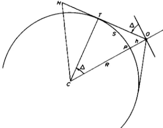
The angular amount Δ by which the visible horizon is depressed because of the height h of the observer above the surface is the geometric dip. Neglect- ing the departure of the Earth from a spherical form, Δ is the angle which the geometric tangent to the Earth from the eye of the observer makes with the direction of the tangent to the surface at the location of the observer (Fig. 38).
FIG. 38. Geometric dip of the horizon: O, observer at height h above the surface of the Earth; 07*, geometric tangent at the geometric horizon T. The geometric horizon at P is perpendicular to CP and at an angle Δ with OT.
This angle is equal to the angle at the center of the Earth between the radii to the observer and to the geometric horizon. Therefore, denoting the radius of the Earth by R,
sin2£A = 4(1 — cos Δ)
or with sufficient accuracy, in radians,
Δ = y/ïh/R.
With h expressed in feet Δ = MS/A; very closely, therefore, the dip of the horizon in minutes of arc, neglecting refraction, is equal to the square root of the height of the observer above the surface in feet.
The distance s on the surface of the Earth from the location of the observer to the geometric horizon is s = ΑΔ. Since an arc of Γ on the surface represents a nautical mile, the distance to the horizon is very closely
s = 1.06 VA nautical miles
= 1.22 yfh statute miles, where h is in feet. The factor 1.22 is very nearly V3/2.
The height h is the amount by which the sea level surface of the Earth curves downward vertically over the distance s on this surface. It is therefore the minimum height which an object at distance s must have in order to be visible to an observer on the surface, or equivalently s is the maximum distance at which an object at a height h above the surface is visible to an observer on the surface, where refraction is neglected, and to the first order in h)R
h = 2R s i n2^
= S*I2R9
s= yJÏRh.
For an observer at a height H, the distance to which an object at a height h is visible, neglecting refraction, becomes
In a distance s of one mile, h amounts to 8 in.
Refraction extends the range of vision to points beyond the geometric horizon, and causes the actual dip to be less than the geometric dip, by variable amounts that depend upon the state of the atmosphere at the time.
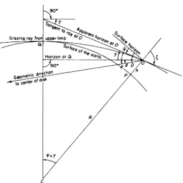
The actual line of sight is tangent at O to the ray which grazes the surface of the Earth at the visible horizon G (Fig. 39). The fundamental equation (44) for refraction gives
sin ζ = . μ& + h)
For a grazing ray, z0 = 90° and k = μ0R; the dip of the horizon is ψ = 90° — ζ, and the angle at the center of the Earth between the radii to the ob- server and to the visible horizon is Θ = ψ + y, where y is obtained from (48),
ay __ tan ζ άμ dh μ dh
The value of Θ in minutes of arc is the distance S = R6 to the visible horizon in nautical miles.
From these equations and an adopted mean state of the atmosphere or a particular theory of astronomical refraction, average values of the total refraction y, the dip ψ, and the distance S to the apparent horizon can be
FIG. 39. Dip of the horizon: C, center of the Earth; y, total refraction, G to O; ψ dip of apparent horizon at O. Geometric depression of center of disk of Sun: At G; d, below the astronomical horizon. At O ; <p = γ + d, below the apparent horizon. At P on the surface vertically below O,
D = ψ + γ + d
= ψ + φ
below the astronomical horizon. The point G on the surface of the Earth lies on the apparent horizon of the observer O ; when the upper limb is apparently on the horizon at 0, d = 34' + semidiameter. Range of vision :
Θ = ψ + γ; arc PG = Rd Θ + d= D.
calculated for different heights. Table I gives values up to h = 100,000 feet, obtained by putting μ = 1 + 0.000 277 p, where p denotes the density of the air, and adopting for p(h) the numerical table for the U.S. Standard Atmosphere of 1935* ; the second column of values for S up to 40,000 feet were obtained from a numerical integration of the differential equation for the grazing ray based on Willis's theory of refraction.
Many different approximate formulas for the dip and the range of vision have been given by different writers. Dividing the values of S in the last
* N.A.C.A. Rept. 538 (1935).
TABLE I
D I P OF THE HORIZON AND RANGE OF VISION
Height (feet) h
250 500 1000 2000 4 000 5 000 6 000 8000 10 000 12 000 14 000 15 000 16 000 18 000 20 000 22 000 24 000 25 000 26 000 28 000 30 000 32 000 34 000 35 000 36 000 38 000 40 000
Total refr.
r
— — 8'.71 — 12M4
14'.65 16'.67 18'.35
— —
— — 24'.06 —
— —
— —
— —
— —
— —
— Dip xpa
— — o°43' — i°or 1°15' 1°27' 1°38' 1°47' 1°56' 2°05' — 2°13' 2°20' 2°28' 2°35/ 2°4r — 2°48' 2°54' 3 W 3°06' 3°1Γ —
rw
3°22'Distance to horizon
S (naut. miles)
(a) —
— — 52 73
89 103 116 127 137 146 — 155 163 172 180 187 — 193 20U 207 214 220 — 226 231
(b) 18.7 26.4 37.3 53.0
— 83.6
— — 117.6
— —
143.7
— — 165.4
— —
184.4
— — 201.6
— —
217.3
— — 231.4
Height (feet) h
42 000 44 000 46 000 48 000 50 000 52 000 54 000 56 000 58 000 60 000 62 000 64 000 66 000 68 000 70 000 72 000 74 000 76 000 78 000 80 000 82 000 84 000 86 000 88 000 90 000 92 000 94 000 96 000 98 000 100 000
Total refr.
r
— —
— —
24'.08
— —
— —
— —
— —
—
— —
—
— —
— —
32'.92 Dip ψα
3°32' riT 3°36' 3°41' 3°46' 3°50' 3°55' 3°59' 4°03' 4o07' 4°ir 4°15' 4°19' 4°23' 4°27' 4°3Γ 4°35r 4°39' 4043/
4°47' 4°51' 4°55' 4°59' 5°03' 5°06' 5°10' 5°14' 5°2T 5°26'
Distance to horizon
S (naut. miles)
(a) 237 242 247 252 257 261 266 271 275 280 284 288 292 296 300 304 308 312 316 320 324 328 332 336 339 343 347 351 355 359
a From J. Sweer, Jour. Optical Soc. Amer. 28, 327-329 (1938).
6 From G. H. Draper and R. F. Haupt, Aero Digest July, 1943.
column of Table I by gives factors that vary from 1.183 for h = 250 feet to 1.157 for h = 40,000 feet, from which we have, to within less than one mile for this interval of height,
S = 1.18 VÂ - 0.0001 h nautical miles, or somewhat less accurately
S = | v h nautical miles
= fVA statute miles.
For purposes of land surveying, determinations of the intervisibility of various points are often required in advance; various graphical methods based on the preceding relations have been devised for determining inter- visibilities from maps.*
Above 100,000 feet (19 miles, or 30.5 km), further refraction may be neglected since the horizontal refraction is already 33' at that height. At greater heights (Table II) the dip of the apparent horizon ψ may be found by adding to the value at 100,000 feet the further effect for the curvature of the Earth alone; this effect is obtained by subtracting the geometric dip at 100,000 feet, 5°35', from the geometric dip Δ at the given height:
ψ = 5°26' + (Δ - 5°35')
= Δ - 9'.
The range of vision is
0 = ψ + 33'
= Δ + 24'.
At a point O at height h above the surface of the Earth, when a celestial object is apparently on the horizon it is rising or setting both at this height and also at the point on the surface where the ray grazes the Earth. The grazing point G on the surface is on the apparent horizon of the observer O (Fig. 39). At G the object is then geometrically at a depression equal to the horizontal refraction, normally 34'; at O the geometric depression below the apparent horizon is 34' + γ9 where y is the amount of the further atmospheric refraction from G to O.
Similarly, at any time before rising or after setting at height A, when at a point on the apparent horizon the depression at the surface is d, the depression
* See, e.g., J. Loodts, La détermination en cabinet sur la carte des visées géodésiques.
Bull Géod. No. 26,453-461 (1952); H. A. L. Shewell, Intervisibility of points onthesurface of the Earth. Empire Survey Rev. 16, 276-279 (1962).
h (miles)
20 30 40 50 60 70 80 90 100 200 300 400 500 600 700 800 900 1000
DIP OF
Δ 5°45' 7°02' 8°06' 9°03' 9°54' 10°42' 11°26' 12°06' 12°44' 17°50' 21°37' 24°44' 27°23' 29°43' 31°49' 33°42' 35°26' 37°02'
TABLE II THE HORIZON
V 5°36' 6°53' 7°57' 8°54' 9°45' 10°33' 11°17' 11°57' 12°35' 17°41' 2Γ28' 24°35' 27°14' 29°34' 31ο40' 33°33' 35°17' 36°53'
AT GREAT HEIGHTS h
(km) 40 50 60 70 80 90 100
150 200 250 300 350 400 450 500 600 700 800 900 1000
Δ 6°24' 7°09' 7°50' 8°27' 9°02' 9034/
10°05'
η ^ δ ' 14°10' 15°48' 17°15' 18°34' 19°47' 20°55' 21°59' 23°56' 25°43' 27°19' 28°48' 30°ir
Ψ 6°15' 7°00' 7°4Γ 8°18' 8°53' 9°25' 9°56'
12°09' i4°or 15°39' 17°06' 18°25' 19°38' 20°46' 21°50' 23°47' 25°34' 27°10' 28°39' 30°02'
below the apparent horizon at height h is ψ = d + γ.
At the surface vertically below O, the depression is D = φ + ψ
where ψ is the dip of the apparent horizon at height h (see Table III).
The zenith distance is 90° + D; the hour angle may be found from the zenith distance, declination, and latitude by any of the usual trigonometric formulas, e.g., by (30), or from appropriate tables or graphs. From the hour angle and the semidiurnal arc, which is the hour angle at rising or setting at the surface, the interval of time between rising or setting at the
TABLE III
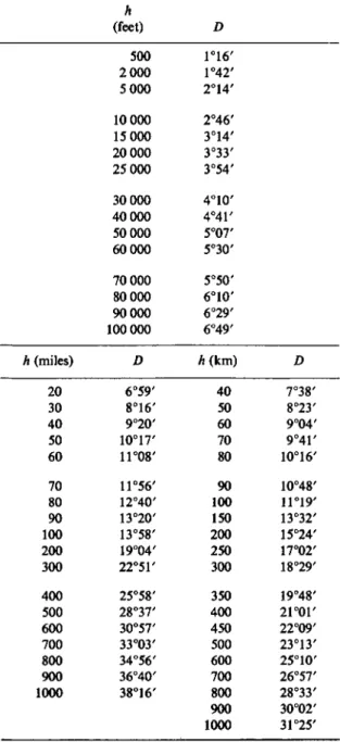
GEOMETRIC DEPRESSION D OF THE CENTER OF THE SUN AT THE SURFACE OF THE EARTH WHEN THE UPPER LIMB
IS ON THE APPARENT HORIZON AT HEIGHT h
h (miles) 20 30 40 50 60 70 80 90 100 200 300 400 500 600 700 800 900 1000
h (feet)
500 2 000 5 000 10 000 15000 20000 25 000 30 000 40000 50 000 60 000 70 000 80 000 90 000 100 000 D 6°59' 8°16' 9°20' 10°17/ 11°08' 11°56' 12°40' 13°20' 13°58' 19°04' 22°51' 25°58' 28°37' 30°57' 33°03' 34°56' 36°40' 38°16'
D 1°16' 1°42' 2°14' 2°46' 3°14' 3°33' 3°54' 4°10' 4°41' 5°07' 5°30' 5°50' 6°10' 6°29' 6°49' h (km)
40 60 50 70 80 100 90 150 200 250 300 400 350 450 500 600 700 800 900 1000
D 7°38' 8°23' 9°04' 9°4Γ 10°16' 10°48' 11°19' 13°32' 15°24' 17°02' 18°29' 19°48' 2i°or 22°09' 23°13' 25°10' 26°57' 28°33' 30°02' 31°25'
surface and any given depression φ at height h may be found. At sufficiently small heights, the differential formula (95) with dz = D may be used.
In this way, for example, corrections may be found to the times of sunrise, sunset, and twilight at the surface that will give the times of these phenomena at any given height above the surface. When the upper limb of the Sun is apparently on the horizon at height A, normally d is 50' for the center of the disk. The depression that must be reached in order to give any particular level of twilight illumination, or for virtual darkness, at a given height can be determined only by observation. The only general statement that can be made is that the duration of twilight rapidly diminishes with height. At sufficiently great heights twilight is unimportant, and the interval from sunset to sunrise is essentially the duration of darkness, although some light is scattered all through the shadow of the Earth by the atmosphere as is evident from the appearance of the Moon during a total eclipse.
The table of the geometric depression of the center of the Sun at the surface of the Earth as a function of the height at which the upper limb is rising or setting may be used inversely to determine the height at which the Sun is rising or setting when at any given depression at the surface. The height calculated in this way is the height of the lower limit of the sunlit region at the zenith of an observer on the surface when the Sun is at the given depression below his horizon; a point at any greater height vertically above the surface will be in the sunlit region of the atmosphere.
A similar theory applies after apparent rising or before setting at 0, when the point where the ray is nearest the surface of the Earth and parallel to it is at a height //vertically above the Earth instead of grazing the surface.*
Sequence of the Reductions for Circumstances of Observation
The order in which the successive reductions are made may be important;
and extreme care is often required in constructing or using tables for the corrections, especially when two or more corrections are combined in a single table. For example, in the horizon coordinate system, an observed altitude relative to the visible horizon must be corrected for dip, when appreciable, before the altitude is used as an argument to enter a refraction table. This has sometimes been overlooked in constructing double-entry tables with observed altitude and height of eye as arguments for obtaining the complete altitude correction, and the error becomes appreciable for low altitudes and heights greater than 100 feet; but a correct table of this form can readily be constructed.
* For a particular example of this problem, in which h = 257 km, outside the limit of effective atmospheric refraction, and which illustrates the principle in Fig. 14, Chapter 5, see Astr. Jour. 68, 348-351 (1963).
Similarly, the observed altitude corrected for dip must next be corrected for refraction, before the altitude is used as an argument to obtain the parallax correction; however, this correction can be incorporated in the construction of a parallax table, so that the table may be entered with the observed altitude corrected only for dip.
In correcting for parallax, the observed position that is used is for the time antedated/or aberration, but the correction that is applied is the correction for the time of observation.
In addition to the correction for dip when required, and the corrections for refraction and parallax, an observation of the upper or lower limb of the Sun or the Moon must be corrected for semidiameter. The correction for semidiameter may be applied either before or after the correction for parallax, but in the case of the Moon considerable care is necessary because of the augmentation. The semidiameter tabulated in ephemerides is the geocentric semidiameter. The augmentation is the difference between the parallax corrections for the center and the limb. After the observed altitude of the limb of the Moon has been corrected for dip and for refraction, the applica- tion of the parallax correction next, to obtain the geocentric altitude of the observed limb, followed by the addition or subtraction of the tabular semi- diameter according as the lower or the upper limb has been observed, gives the geocentric altitude of the center of the disk; but if a correction for semidiameter is applied before the parallax correction, the tabular semi- diameter must be increased by the amount of the augmentation, in order to obtain the topocentric altitude of the center of the disk. When the parallax correction is applied first, it implicitly includes the effect of augmentation, and no explicit calculation of the augmentation is required.
The augmentation of the horizontal parallax with latitude is neglected for navigational purposes.
The correction for parallax implicitly contains the only reduction that is required for the effect of the form of the Earth on the aspect of the celestial sphere. The celestial coordinate systems, and the astronomical latitude and longitude on the surface of the Earth, are independent of the form of the Earth, since they are defined without any reference to the form of the surface.
Astronomical observations are referred to the abstract geometric reference circles of these coordinate systems, not to the surface of the Earth; e.g., the angular distance of a celestial object from the visible horizon is not its altitude. The observed positions of nearby celestial objects depend upon the position of the observer relative to the center of the Earth, and therefore upon the form of the surface; but this effect is included in the parallax, through the dependence of the parallax upon the geocentric distance of the observer. The geocentric distance is determined by the form and dimensions of the sea level surface and the elevation of the observer above sea level.
The parallax is the only correction required when observations are referred to the astronomical horizon, regardless of the height above sea level. On an isolated elevation, if the observation is referred to the visible horizon, the correction for dip is required to reduce the observation to the astronomical horizon at the height of the observer.
Apparent rising and setting depend on the topocentric parallax; but to the usual accuracy of calculation, and within the inevitable uncertainties from refraction, the effect of the difference from the sea level value is negligible, even for the Moon.
The Geographic Reference System
In the astronomical system of geographic coordinates, the latitude and longitude of a point on the irregular physical surface of the Earth are determined by the local astronomical vertical at this point, independently of the topographical situation of the point. The direction of the vertical is normal to the equipotential surface of gravity that passes through the point, and since the equipotential surfaces are not similar and parallel to one another, the astronomical latitude and longitude depend upon position in the vertical direction as well as in the horizontal direction. The level surfaces of gravity in general converge toward the poles, and the astronomical vertical is a curve which lies in the plane of the meridian and is concave toward the axis of rotation; but the curvature of the actual vertical is irregular because of the irregularities in gravity from point to point. For many purposes, reductions of the geographic coordinates, and of other observed quantities, to sea level or to some other common equipotential surface are necessary.
In principle, the corrections to directly measured quantities required because of the nonparallelism of the level surfaces may be derived from the formula for theoretical gravity; but in practice, only approximate corrections can be obtained in this way because of the local gravity anomalies, and it is more
satisfactory to use actual values of gravity obtained with gravimeters.
A measure of the elevation of a point above sea level may be defined in several different ways; e.g., as the distance from the geoid measured along the irregularly curved vertical through the point, or as the perpendicular distance from the point to the geoid, or in still other ways.*
For the determination of elevations, three different methods are used, according to circumstances. Precise determinations are made with the geodetic spirit level; successive sights are taken over short distances along different level surfaces, and the differences of elevation are measured normal to these surfaces by means of a graduated rod. Since the level surfaces are not parallel, the sum of the measured differences of elevation is not exactly the
* See, e.g., Bull. Géod. N o . 32, 107-145 (1954).
same as the difference in elevation between the end points of the line of levels, and if the leveling were carried out along a different route a slightly different result would in general be obtained. A correction, known as the orthometric correction, is therefore necessary to obtain the elevation of a point referred to sea level; on one line of precise spirit leveling from San Diego, California, to Seattle, Washington, which runs much of the way over high ground, this correction amounts to 1.25 meters. Less accurate determinations are made by trigonometric leveling, in which differences of elevation are calculated from measured vertical angles and horizontal distances. Approximate elevations may be obtained by barometric leveling, in which the elevation is determined from the relation of the barometric pressure of the atmosphere to height above sea level.
The determination of height above sea level does not depend upon astronomical observations, but the variations and deflections of the vertical affect the measurements. In particular, precise leveling is appreciably affected under some circumstances by the lunisolar variations of the vertical; it is also affected by deformations of the surface of the Earth, e.g., the diurnal oscillations due to thermal effects. Deformations of the surface of the Earth do not directly affect the astronomical vertical in space, and therefore do not alter the latitude; but they disturb the adjustments of the instruments with which determinations are made.
The correction to a line of leveling s kilometers long, in azimuth a, on a rigid Earth, for the lunisolar variations of the vertical is, in units of 0.01 mm,
Δ/f = {k sin 2z cos(A — OL)}S,
where k = 8.5 for the Moon and 3.9 for the Sun, z denotes the zenith distance, and A the azimuth. The application of this formula in practice is facilitated by nomograms, tables, or approximations adapted to particular circumstances.
In the geodetic reference system the geographic coordinates are determined by computation from geometric measurements on the surface of the Earth, instead of by astronomical observations that determine the coordinates directly, and they are independent of the irregularities and variations of the astronomical system. However, astronomical observations are an essential auxiliary in geodetic surveys, both to control the particular errors of observa- tion to which geodetic measurements are peculiarly liable and to determine the geoid and establish a connection with the astronomical system. Moreover, the geodetic measurements, like astronomical observations, are made on the irregular physical surface of the Earth, with instruments which are oriented by means of the plumb line and level; and in the computation of geodetic coordinates, the directly measured quantities require reductions to the
reference spheroid which depend both upon local gravity and upon the geometric properties of the ellipsoid.
Reductions to Sea Level
Were it not for the irregularities in the curvature of the vertical, the astronomical longitude would be independent of elevation; but the latitude still would vary along the vertical. The level surfaces, in converging toward the poles, slope downward toward sea level; and the height h of an equi- potential surface above sea level therefore decreases at the rate dhjds = tan /, where / is the inclination of this surface to the sea level surface, and s is distance poleward on the sea level surface. With sufficient accuracy ds = R άφ, where R is the radius of the Earth, and / = dhjR dy. The angle / is also the angle which the vertical at height A makes with the direction of the vertical at sea level. Consequently, the astronomical latitude at height h is greater than at sea level by the amount of /. On the equipotential surface, gh = const. ; differentiating, and dividing by gh d<p, we obtain dgjg d(p + dhjh άφ = 0, and therefore
j __ __ h dg Rgd(p
If the intensity of gravity on the geoid conformed to the theoretical expression for the intensity on the reference spheroid,
g = ge(\ + b sinV),
the correction that would be required to the directly observed latitude at an elevation h to reduce it to sea level would therefore be, to a sufficient approxi- mation,
A b sin 2α?, R
= -0".000 052 h sin 2 <p, hin feet
= -0".000 171 h sin 2 φ, hin meters
This correction is regularly applied in geodetic practice; but because of the anomalies of actual gravity, it cannot be regarded as more than a rough approximation.
Additional reductions due to the geometric properties of the ellipsoid are sometimes required in precise work. For example, the geodetic verticals through two different points do not lie in the same plane unless both points have either the same geodetic latitude or the same geodetic longitude. In sighting from one point to another with an instrument oriented by plumb line or level, the horizontal angle which is actually measured is the azimuth of the
plane that passes through the line of sight and the local vertical at the point of observation. This plane in general does not contain the vertical through the other point, but only intersects it at this observed point. Consequently, the observed azimuth differs from the azimuth of the vertical projection upon the spheroid by an amount depending on the height of the observed point.
The correction required to an observed azimuth A, reckoned from south through west, of a point at an elevation h to obtain the azimuth of the projec- tion of the point on the reference ellipsoid is
e2h
ΔΑ = H cos2® sin 2A seconds of arc, 2a sin 1"
where e denotes the eccentricity, and a the equatorial radius, of the ellipsoid.
In latitude 45°, at h = 1000 meters, the correction to an azimuth of 45° is only 0".055. Ordinarily, this correction is negligible, but it is sometimes applied. The largest values of the correction that occur in the transcontinental triangulation of the United States are where the arc goes through the Rocky Mountains, and these corrections are less than 0".30.
Determination of Geographic Position
The determination of position on the surface of the Earth in latitude and longitude by means of astronomical observations depends upon the general principle that at any instant the sky presents a different aspect from each point on the Earth; and by observing this aspect, the geographic position of the observer may be inferred. The navigator, e.g., observing a celestial body in a particular* place in the sky, and obtaining its position on the rotating celestial sphere from an ephemeris, determines what his location on the Earth must be in order that this body may be seen in its observed place in the sky at that time.
The simplest illustration is the familiar example of the polestar, which, as we travel over the curved surface of the Earth, is always seen very nearly due north, but at different altitudes above the horizon, depending on geo- graphic latitude, and which may therefore be used to determine latitude as well as direction, though it is of no aid in finding longitude. Likewise, the meridian altitude of a celestial body of known declination gives the latitude, and has been used since early times to obtain latitude at sea from noon observations of the Sun.
The particular relations between geographic position and the appearance of the celestial sphere which are the basis of practical methods for determining time, direction, longitude, and latitude depend upon whether the observations are to be made with precision instruments at a fixed astronomical observatory,
or with the less precise portable instruments that must be used in surveying, or under the severe limitations imposed upon the navigator at sea or in the air. For any particular purpose, the relations which are needed may be obtained from the general formulas that connect the coordinates in the equatorial, the horizon, and the geographic systems with one another.
Innumerable methods of determining latitude, longitude, azimuth, and local time, separately or in various combinations, by observations of one, two, or more stars or other celestial objects, may be devised on the basis of different combinations and special cases of the general relations; and a large number of the methods that are possible in principle have been found useful in practice, according to circumstances.
The methods, instruments, and techniques of observation ordinarily used for determinations of geographic position are described in detail in textbooks of practical astronomy, geodesy, surveying, and navigation. Examples of their application, and variants adapted to special circumstances, continually appear in the periodical literature of these subjects. The relative advantages of the different methods that are feasible for a particular purpose with the means available depend in general upon the errors to which the required initial data and the necessary observations are liable, and the relative effects of these errors upon the results. The principal problem in any method is to determine a selection of stars, and a program of observations with the particular instrument used, that will minimize the various errors.
The accuracy obtained by a given method is often greatest when the observations are made at special times, e.g., at meridian transit, or prime vertical passage, or on an object which is near the zenith. In many cases, it is especially advantageous to make the observations on close circumpolar stars. For this reason, Polaris is widely used for the determination of latitude and azimuth in latitudes where it is observable.
Many of the usual methods become impracticable or fail completely at very high latitudes. In particular, precise azimuth determinations become increasingly difficult beyond latitude 50°, and the standard method of Polaris observations is unsatisfactory; other methods, depending on stars nearer the equator, are then more advantageous even though errors in the time of observation have greater effect.
At sea or in the air, the only astronomical observation that is practicable with sufficient accuracy is the measurement of altitude; the navigator must therefore determine his position on the surface of the Earth by observing positions of celestial bodies relative to the local horizon, without depending upon their directions in azimuth. For the measurement of altitude, the sextant introduced in the early eighteenth century, with later improvements, is now used; in earlier times, the quadrant, the astrolabe, and the cross-staff were common instruments.
The practices that became established in navigation during early modern times were characterized by the determination of latitude and longitude each separately by distinct observations. Latitude was determined from altitudes at culmination, usually from a noon sight on the Sun, or from Polaris; the traditional noon sight is still commonly taken at sea. Reasonably approxi- mate latitudes could be determined by this principle even in ancient times. In contrast, the determination of longitude involved practical difficulties that were not satisfactorily overcome until a late date. The astronomical determi- nation of longitude depends in principle upon finding the difference between the local time, and the time on the zero meridian at the same instant. The local time may be determined from astronomical observations, but the determination of Greenwich time was in practice an almost insuperable difficulty before the development of precise timepieces that would run accurately on shipboard.
After accurate chronometers became available, longitude was determined by finding the local time from a sight on an object bearing nearly east or west.
For example, an observed altitude of the Sun early in the morning or late in the afternoon, with the declination from the nautical almanac and the latitude from dead reckoning, gives the hour angle of the Sun by (30), or local apparent solar time. With the equation of time from the almanac, and the Greenwich time of observation from the chronometer, the longitude is readily obtained.
The practice of determining latitude and longitude each separately has now been superseded by methods based on the principle that the observed zenith distance of a celestial body is the angular distance on the surface of the Earth from the observer to the point where the body is in the zenith. The geographic latitude of this substellar point is the declination of the body, and its longitude is the Greenwich hour angle. The almanacs issued for sea and air navigation tabulate the Greenwich hour angle and declination of the Sun, Moon, and bright planets directly; for the navigational stars, they tabulate the sidereal hour angle and declination, together with the Greenwich hour angle of the equinox. The geographic position of the substellar point at the time of observation may therefore be immediately found from the almanac. The observer is somewhere on the circle that is centered at this point and has an angular radius equal to the observed zenith distance. From observations of two celestial objects, or of a single object at two times with allowance for the motion of the observer during the interval, two of these circles of position may be determined which intersect at the location of the observer.
The two circles also intersect at a second point, but with a proper choice of objects to be observed the two intersections are always sufficiently far apart to prevent any doubt as to which one is the observer's position; e.g.,
the objects must not be in nearly the same azimuth. A common rule is
"one ahead and one on the beam"; or, for a three-star fix, which is often used because it provides a check, "equally spaced in azimuth." It is neither necessary nor feasible for the navigator to plot the actual circle on his chart.
In practice, he plots a short straight line that represents a very small arc of the circle in the vicinity of his dead reckoning position; this line is known as the line of position. The line of position was discovered in 1837 by the American navigator Captain Sumner, and is often referred to as the Sumner line.*
The method now in use for determining it was introduced later by the French navigator Marcq St. Hilaire.
In this method, the altitude and azimuth in which the object would have been observed from an assumed position, either at the dead reckoning position or at a convenient nearby even latitude and longitude, are determined by solving the spherical triangle formed on the surface of the Earth by the substellar point, the pole, and the assumed position; this triangle is the projection of the astronomical triangle upon the surface of the Earth. In practice the necessity for a trigonometric computation is avoided by means of navigation tables which are essentially tabulations of the solution of the triangle. The altitude and azimuth thus obtained give the distance and bearing from the assumed position to the substellar point; the line of position through the assumed position is perpendicular to this bearing. Since the circle of position through the assumed position is necessarily concentric with the circle through the actual position, the line through the assumed position is parallel to the required line except for a small difference, negligible for navigation purposes, due to whatever difference there may be between the bearings of the substellar point from the two positions. The distance between these parallel lines through the two positions is equal to the difference between the observed altitude and the computed altitude ; it may readily be laid off on the chart, and thereby the actual line of position plotted.
The tabular Greenwich hour angle and declination in the almanac are apparent geocentric values, referred to the equator and equinox of date.
For use with these tabular values, the observed altitude is freed from refrac- tion, and from semidiameter and dip if necessary, and reduced to the center of the Earth by applying a correction for parallax when it is appreciable.
At the high speeds of aircraft a further correction is required for an apparent displacement of the zenith known as the Coriolis effect. In motion at a uniform speed along a great circle course relative to the rotating surface of the Earth, the path in space relative to an inertial frame is curved, and therefore an acceleration continually acts perpendicular to the velocity.
This acceleration is directed to the left of the velocity in the northern
* Sumner's own account is quoted in The American Practical Navigator (U.S. Navy Hydrographie Office Publ. N o . 9) and in Sky and Telescope September (1942).