between Binary Shapes
J´ozsef N´emeth
Department of Computer Algorithms and Artificial Intelligence, University of Szeged H-6701 Szeged, P.O. Box 652., Hungary
nemjozs@inf.u-szeged.hu
Abstract. Binary image registration has been addressed by many authors re- cently however most of the proposed approaches are restricted to affine transfor- mations. In this paper a novel approach is proposed to estimate the parameters of a general projective transformation (also called homography) that aligns two shapes. Recovering such projective transformations is a fundamental problem in computer vision with various applications. While classical approaches rely on es- tablished point correspondences the proposed solution does not need any feature extraction, it works only with the coordinates of the foreground pixels. The two- step method first estimates the perspective distortion independently of the affine part of the transformation which is recovered in the second step. As experiments on synthetic as well on real images show that the proposed method less sensi- tive to the strength of the deformation than other solutions. The efficiency of the method has also been demonstrated on the traffic sign matching problem.
1 Introduction
In most of the image processing applications a key step is the registration of images i.e.
the estimation of the transformation which aligns one image to the other (see [17] for a good survey). The overlapped images can be then combined or compared. The esti- mation of the parameters of a projective transformation (also known as planar homog- raphy) between two views of the same planar object has a fundamental importance in computer vision.
Classical landmark based (or correspondence based) methods usually trace back the problem into the solution of a system of linear equations set up using the coordinates of point pairs [7]. These point pairs are usually established by matching the intensity value patterns around the points[9]. On the other hand featureless methods estimate the transformation parameters directly from image intensity values over corresponding regions[10].
In many cases, however, the images do not contain sufficent variety of graylevel values (e.g. images of traffic signs or letterings), or suffered from intensity value dis- tortions (e.g. X-ray images). Although there are some time consuming methods to cope with brightness change across image pairs [8], these conditions make the clas- sical brightness-based methods unreliable. In [5], Francos et al. propose a method for the estimation of a homeomorphism between graylevel images. They showed how to
J. Blanc-Talon et al. (Eds.): ACIVS 2012, LNCS 7517, pp. 374–383, 2012.
c Springer-Verlag Berlin Heidelberg 2012
transform the problem into the solution of a linear system of equations, however they assumed that the intensity values differ only by a zero mean Gaussian noise.
When the segmentations are available it is reasonable to solve the registration prob- lem using the binary versions of the images [13,6]. Most of the current approaches are restricted to affine transformations. For example Domokos et al. showed that it is possible to trace back the affine matching problem to an exactly solvable polynomial system of equations [2]. Affine moments and invariants can also been used to recover linear transformation [15]. In [16] Yezzi et al. proposed a variational framework that uses active contours to simultaneously segment and register features from multiple im- ages. Belongie et al. proposed a nonlinear shape matching algorithm in [1]. The method first establish point correspondences between the binary shapes using a novel similarity metric, called shape context, which consists in constructing a log-polar histogram of surrounding edge pixels. Then it uses the generic thin plate spline model to align the shapes.
In [11], Nemeth et al. proposed a method to estimate the parameters of projective transformations between binary shapes and later it has been extended by Domokos et al.
[3] to more general nonlinear transformations e.g. polynomial and thin plate spline. This method has been proved to be efficient in case of many real applications e.g. matching handwritten characters or aligning multimodal prostate images. Altough this approach proved to be very robust against the strength of the deformation, in some cases (e.g.
when the shapes are rotated more than 90 degrees), it could not find the right solution due to the iterative minimization involved.
In this paper we propose a novel method to estimate the parameters of projective transformations between shapes. The perspective and the affine parts of the transfor- mation are recovered in two sequential steps. It does not need any feature extraction or established correspondences, it works only with the coordinates of the foreground pixels. The performance of the method has been examined on synthetic as well as on real images.
2 The Registration Method
We are looking for a two dimensional projective transformation (also called planar homography)ϕ : R2 → R2,ϕ(x) = [ϕ1(x), ϕ2(x)]T that aligns a pair of binary shapes, so that for any corresponding point pairy= [y1, y2]Tandx= [x1, x2]T on the template and observation shapes:
y=ϕ(x). (1)
A projective transformation in 2D is given by
y1=ϕ1(x) = h11x1+h12x2+h13
h31x1+h32x2+ 1 y2=ϕ2(x) = h21x1+h22x2+h23
h31x1+h32x2+ 1 , (2) wherehij are the elements of theH3×3 matrix (for more details on planar homogra- phy transformations see [7]). SinceH is defined up to scale (it has only 8 degree of
freedom), one of its elements can be fixed (hereinh33 = 1). Furthermore we repre- sent the template and the observation shapes by their foreground regionsFt⊂R2and Fo⊂R2. Thus we can simply write
Ft =ϕ(Fo). (3)
The parametersh31andh32 are responsible for the perspective distortion, while the others effect affine transformation (translation, rotation, scaling and shearing). These two parts of the transformation can be performed one after the other, so thusϕcan be decomposed as follows:
ϕ=ϕa◦ϕp (4)
whereϕp :R2→R2,ϕp(x) = [ϕp1(x), ϕp2(x)]T is a nonlinear transformation:
ϕp1(x) = x1
p1x1+p2x2+ 1 ϕp2(x) = x2
p1x1+p2x2+ 1, (5) resulting only perspective distortion. andϕa :R2→R2,ϕa(x) = [ϕa1(x), ϕa2(x)]T is an affine transformation:
ϕa1(x) =a11x1+a12x2+a13
ϕa2(x) =a21x1+a22x2+a23, (6) Thus we can write the relationship between the shapes as follows:
Ft= (ϕa◦ϕp)(Fo) =ϕa(ϕp(Fo)) (7) The proposed method estimates thepiparameters of the perspective componentϕpand theai parameters of the affine componentϕa in two distinct steps, then using Eq. (4) we can get thehijparameters ofϕas follows:
h11=a11+p1a13, h12=a12+p2a13, h21=a21+p1a23, h22=a22+p2a23,
h13=a13, h23=a23, h31=p1, h32=p2 (8) 2.1 Step 1: Estimation of the Perspective Distortion
If Eq. (7) stands then there is only an affine transformation betweenFtandϕp(Fo), thus for any affine-invariant functionI:R2→R:
I(Ft) =I(ϕp(Fo)). (9) Note that the unknowns of this equation are thepiparameters ofϕp. Moreover as we will show for given values ofp1andp2using traditional moment-based affine invariants the right hand side of the equation can be efficiently estimated using only the jacobian
ofϕp, so it is not necessary to actually generate the imageϕp(Fo)which would be very time-consuming.
The basic idea of the proposed method is that given a set of independent affine in- variant functionsIi:R2→R,i= 1. . . nwe obtain a system of equations:
Ii(Ft) =Ii(ϕp(Fo)). (10) The parameters of ϕp are obtained as the solution of this system of equations. It is clearly a highly nonlinear system and thus do not have exact solution. However as experimental results show it can be efficiently solved by a general nonlinear solver.
Although any set of affine invariant functions could be appropriate, herein we use affine moment invariants [4], because it allows a very efficient numerical estimation of the system of equations in Eq. (10). The left hand sides of the system of equations Eq. (10) do not depend on the parameters ofϕp so can be estimated directly using the point coordinates of the template image. The geometric momentmrsof order(r+s) of a shapeFis defined as
mrs(F) =
Fxr1xs2dx. (11) The affine moment invariantsIi of a shape are rely on the so called central moments that are defined as follows:
μrs(F) =
F(x1−c1)r(x2−c2)sdx (12) where the coordinates of the center of mass of the shape is given by using the geometric moments:
c1= m10(F)
m00(F) and c2=m01(F)
m00(F). (13)
The affine moment invariantsIi(F)then are obtained using these central moments. For example the first two affine moment invariants are given as follows:
I1= (μ20μ02−μ211)/μ400
I2= (−μ230μ203+ 6μ30μ21μ12μ03−4μ30μ312
−4μ321μ03+ 3μ221μ212)/μ1000. (14) For more on affine moment invariants see [4].
Given fixed parameters ofϕp we show how to compute the right hand side of the equations Eq. (10) avoiding the generation of the imageϕp(Fo)by making use of the JacobianJϕpof the transformation. For a shapeFthat is distorted byϕpthe geometric moment can be estimated as follows:
mrs(ϕp(F)) =
F[ϕp1(x)]r[ϕp2(x)]sJϕp(x)dx (15) where the Jacobian of the perspective distortion is given by
Jϕp(x) = 1
(p1x1+p2x2+ 1)3,
(for more details on the usage of the Jacobian and mathematical derivation of such equa- tions see [5] and [3]). On the perspectively distorted shapeϕp(F)the central moments are given by
μrs(ϕp(F)) =
F[ϕp1(x)−c1]r[ϕp2(x)−c2]sJϕp(x)dx, (16) where
c1= m10(ϕp(F))
m00(ϕp(F)) and c2=m01(ϕp(F))
m00(ϕp(F)). (17) For fixed values of the parametersp1andp2the affine moment invariantsI(ϕp(F))in the right hand side of the system Eq. (10) can be obtained using the central moments in Eq. (16) that can be estimated using only the foreground points of the shapeF. Thus we avoid to generate theϕp(F)images which would be very time consuming.
2.2 Step 2: Estimation of the Affine Transformation
After the perspective distortion is recovered (i.e. its parametersp1 andp2 are deter- mined) the affine transformationϕashould be estimated between shapesFtandϕp(Fo). For that purpose we used the approach proposed in [2] and, as in the previous section, in order to avoid the generation ofϕp(Fo)we modified the method by making use of the JacobianJϕpof the perspective part. The following system of equations
Ft
ynkdy=Jϕa
n
i=1
n
i
i
j=0
i j
an−ik1 ai−jk2 ajk3
Fo
ϕp1(x)n−iϕp2(x)i−jJϕp(x)dx (18) forn= 1,2,3andk = 1,2can be written for theaij parameters of the affine trans- formation. This system contains six polynomial equations up to order three which is enough to solve for all unknowns.
The Jacobian of an affine transformation is constant over the whole plane, thus it can be simply estimated as the ratio of the areas of the shapes:
Jϕa=
Ftdy
FoJϕp(x)dx (19)
However the system Eq. (18) may have many solutions, we can select the real root which gives the same determinant as what we computed in Eq. (19). Note that the solution is not unique if the shape is affine symmetric.
Putting together the projective transformationϕp and the affine transformationϕa using Eq. (8) we get the hij parameters of the aligning planar homography transformationϕ.
2.3 Implementational Issues
Altough the two unknowns of the perspective partϕpwould necessitate only two equa- tions i.e. two invariants in system Eq. (10), the independence of the chosen set of affine
Algorithm 1. Pseudo code of the proposed algorithm Input : Binary images: template and observation
Output: Thehijparameters of the aligning planar homography Choose a set of affine invariantsIi:R2→R(i= 1, . . . , n)
1
The solution of the system of equations Eq. (10) gives the perspective parametersp1and
2
p2
Solve the system of equations Eq. (18) to determine the affine parametersaij 3
Use Eq. (8) to obtain thehijparameters of the aligning planar homography
4
moment invariants is not garanteed. Accordingly we obtained better results with overde- termined systems. The results shown in Section 3 was attained using the{I3, I4, I5, I6} set of invariants. Since the system is clearly nonlinear we found that it could be solved effenciently using nonlinear optimization methods. We used the standard differential evolution [14] method in the tests presented in Section 3. The equations are constructed in the continuum but in practice we only have a limited precision digital image. Conse- quently, the integrals over the continuous domainsFtandFocan only be approximated by discrete sums over the set of foreground pixels denoted byFtandFo.
The pseudo code of the proposed algorithm can be found in Algorithm 1 while Fig. 1 shows example result images after the two subsequent steps of the method.
Template Observation Step 1 Step 2
Fig. 1. The registration process: The first step removes only the perspective distortion from the observation image while the second step restores the affine transformation and thus align it to the original template image
3 Experiments
The performance of the proposed method has been tested on a large synthetic dataset consist of 35 different template shapes and their projectively distorted versions as ob- servations a total of≈1100images of size300×300. The applied projective transfor- mations were randomly composed of0.5, . . . ,1.5scalings;−π4, . . . ,π4 rotations along thexandy axes and−π, . . . , πalong thezaxe;−1, . . . ,1translations along bothx andyaxis and0.5, . . . ,2.5along thezaxis; and a random focal length chosen from the [0.5,1.5]interval.
Registration results were quantitatively evaluated using two kind of error measures.
The first one (δ) measures the percentage of the non-overlapping area of the template
Template Observation Shape Context Domokos et al. Proposed
Fig. 2. Example images from the synthetic data set and registration results obtained by Shape Context [1], Domokos et al. [3] and the proposed method. The template and the registered observation were overlaid, overlapping pixels are depicted in gray whereas nonoverlapping ones are shown in black.
and the registered observation whilemeasures the distance (in pixels) between the true ϕand the estimatedϕˆtransformation:
δ= |FrFt|
|Fr|+|Ft|·100%, = 1
|Fo| x∈Fo
ϕ(x)−ϕ(x),ˆ
whereFr denote the set of foreground pixels of the registered template respectively.
The summary of the results is shown in Table 1.
For comparison we examined the results of Domokos et al. [3] on the same dataset.
It provided weaker results since could not cope with cases when the images were ro- tated more than 90 degrees. We have also compared the performance of our method to that of Shape Context [1], a more general shape matching algorithm developed for nonlinear registration of binary images. For testing, we used the program provided by the authors, its parameters were set empirically to their optimal value (beta init =30, n iter=30, annealing rater =1).
The average running time of the Domokos et al. and the proposed method (C im- plementations) were 4.75 sec. and 12.86 sec. respectively. The runtime of the Matlab implementation of Shape Context (68.87 sec.) is not authoritative.
Table 1. Test results on the synthetic dataset of Shape Context, Domokos et al. and the proposed method.m,μ, andσdenote the median, mean, and deviation.
δ(%) (pixel)
m μ σ m μ σ
Shape Context 10.10 13.36 11.02 - - -
Domokos et al. 10.54 14.31 13.99 151.60 122.72 87.21 Proposed 2.38 6.23 12.34 1.88 23.46 53.00 3.1 Traffic Signs
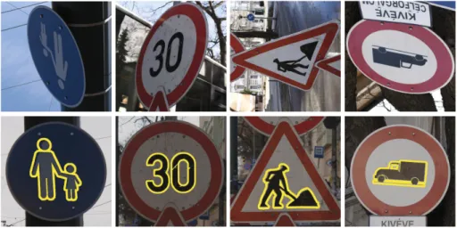
The recognition of traffic signs has an increasing importance in the car industry. The orientation of the sign is also important to decide wether it should be taken into con- sideration and it can be determined by registering the projectively distorted sign to a template. Herein we used classical thresholding however automatic detection and seg- mentation is also possible [12]. Fig. 3 shows some registration results of the proposed method. Recently, in [11] it has been shown that Shape Context[1] and SIFT[9] are unsuitable to extract point correspondences between traffic sign image pairs.
Fig. 3. Registration results on traffic signs. The images used as observations are shown in the first row, and below them the corresponding templates with the overlayed contours of the registration results.
4 Conclusion
We have proposed a novel approach to recover projective transformations of planar shapes. The two-step solution first estimates the perspective distortion independently of the affine part of the transformation which is recovered in the second step. While classical image registration algorithms use feature correspondences our method works with invariant moments estimated using the point coordinates of the whole object. The efficiency of our method has been demonstrated on synthetic dataset as well as on real
traffic sign images. Comparative test showed that our algorithm outperform other meth- ods, especially in the case of strong deformations e.g. when the shapes are rotated more than 90 degrees. The examination of the robustness of the method against different level of segmentation errors will be the subject of future research.
Acknowledgements. This research was supported by the European Union and the European Regional Development Fund under the grant agreements T ´AMOP-4.2.1/B- 09/1/KONV- 2010-0005 and T ´AMOP-4.2.2/B-10/1-2010-0012.
References
1. Belongie, S., Malik, J., Puzicha, J.: Shape matching and object recognition using shape con- text. IEEE Transactions on Pattern Analysis and Machine Intelligence 24(4), 509–522 (2002) 2. Domokos, C., Kato, Z.: Parametric estimation of affine deformations of planar shapes. Pat-
tern Recognition 43(3), 569–578 (2010)
3. Domokos, C., Nemeth, J., Kato, Z.: Nonlinear shape registration without correspondences.
IEEE Transactions on Pattern Analysis and Machine Intelligence 34(5), 943–958 (2012) 4. Flusser, J., Suk, T., Zitov´a, B.: Moments and Moment Invariants in Pattern Recognition.
Wiley & Sons (October 2009)
5. Francos, J., Hagege, R., Friedlander, B.: Estimation of multidimensional homeomorphisms for object recognition in noisy environments. In: Proceedings of Conference on Signals, Sys- tems and Computers, vol. 2, pp. 1615–1619. Pacific Grove, California (2003)
6. Guo, H., Rangarajan, A., Joshi, S., Younes, L.: Non-rigid registration of shapes via diffeo- morphic point matching. In: Proceedings of International Symposium on Biomedical Imag- ing: From Nano to Macro, vol. 1, pp. 924–927. IEEE, Arlington (2004)
7. Hartley, R.: In defense of the eight-point algorithm. IEEE Transactions on Pattern Analysis and Machine Intelligence 19(6), 580–593 (1997)
8. Kaneko, S., Satohb, Y., Igarashi, S.: Using selective correlation coefficient for robust image registration. Pattern Recognition 36, 1165–1173 (2003)
9. Lowe, D.G.: Distinctive image features from scale-invariant keypoints. International Journal of Computer Vision 60(2), 91–110 (2004)
10. Mann, S., Picard, R.W.: Video orbits of the projective group a simple approach to featureless estimation of parameters. IEEE Transactions on Image Processing 6(9), 1281–1295 (1997) 11. Nemeth, J., Domokos, C., Kato, Z.: Recovering planar homographies between 2d shapes. In:
Proceedings of International Conference on Computer Vision, pp. 2170–2176. IEEE, Cairo, Egypt (2009)
12. Paulo, C.F., Correia, P.L.: Automatic detection and classification of traffic signs. In: Proc.
of Workshop on Image Analysis for Multimedia Interactive Services, Santorini, Greece, pp.
11–14 (June 2007)
13. Simonson, K.M., Drescher, S.M., Tanner, F.R.: A statistics-based approach to binary image registration with uncertainty analysis. IEEE Transactions on Pattern Analysis and Machine Intelligence 29, 112–125 (2007)
14. Storn, R., Price, K.: Differential evolution - a simple and efficient heuristic for global opti- mization over continuous spaces. Journal of Global Optimization 11(4), 341–359 (1997)
15. Suk, T., Flusser, J.: Affine Normalization of Symmetric Objects. In: Blanc-Talon, J., Philips, W., Popescu, D.C., Scheunders, P. (eds.) ACIVS 2005. LNCS, vol. 3708, pp. 100–107.
Springer, Heidelberg (2005)
16. Yezzi, A., Z¨ollei, L., Kapurz, T.: A variational framework for joint segmentation and regis- tration. In: Proceedings of IEEE Workshop on Mathematical Methods in Biomedical Image Analysis, pp. 44–51. IEEE, Kauai (2001)
17. Zitov´a, B., Flusser, J.: Image registration methods: A survey. Image and Vision Comput- ing 21(11), 977–1000 (2003)
![Fig. 2. Example images from the synthetic data set and registration results obtained by Shape Context [1], Domokos et al](https://thumb-eu.123doks.com/thumbv2/9dokorg/1174660.86033/7.659.73.587.73.459/example-images-synthetic-registration-results-obtained-context-domokos.webp)