buildings
Article
Relief Method: The Analysis of Architectonic Façades by Fractal Geometry
Vilmos Katona
Citation: Katona, V. Relief Method:
The Analysis of Architectonic Façades by Fractal Geometry.Buildings2021, 11, 16. https://doi.org/10.3390/
buildings11010016
Received: 10 November 2020 Accepted: 28 December 2020 Published: 31 December 2020
Publisher’s Note:MDPI stays neutral with regard to jurisdictional claims in published maps and institutional affil- iations.
Copyright: © 2020 by the author.
Licensee MDPI, Basel, Switzerland.
This article is an open access article distributed under the terms and conditions of the Creative Commons Attribution (CC BY) license (https://
creativecommons.org/licenses/by/
4.0/).
Simonyi Károly Faculty of Engineering, Wood Sciences and Applied Arts, University of Sopron, 9400 Sopron, Hungary; katona.vilmos@uni-sopron.hu or katwilat@gmail.com; Tel.: +36-70-236-2075
Abstract:This paper explores the working hypothesis that fractal patterns that closely match those found in nature are more likely to convey a strong sense of genius loci to humans by comparison with ‘Euclidean’ patterns that do not occur in nature frequently. A part of this survey is concerned with showing the pattern-conscious thinking, regarding the façade composition and material tex- tures, of historical buildings compared to different ecological or geological scenes. We also examine the background of pattern-design from architectural theory, and extrapolate the matter to certain questions about spatial quality, tectonics, and the phenomenon of place. Our most important concern is an attempt to enhance architectural arguments regarding place and character with mathematical calculations. We introduce ‘relief method’ as a possible way to capture the haptic nature of archi- tecture beyond the patterns of its two-dimensional projections. Through this approach, façades are considered as reliefs and pictures at the same time, thus reflecting the tension between their materiality and visual representation. Fractal geometry also helps to understand how architectonic layers define scale, and by which means architecture could be translated into the human level of physical existence.
Keywords:façades; tectonics; design patterns; scaling; fractals; Hausdorff dimension; genius loci
1. Introduction
Architectural theories of the past decades have showcased a multiverse of possibilities and creative approaches, all the while blurring the boundaries between the various schools and disciplines. We have witnessed the competing theories of tectonic culture versus deconstructivism, or critical regionalism versus the ‘manager avant-garde’; in the midst of these competing theories lies a theoretical nexus where these multiverses intersect. It is here where we may exchange information, conceptualize new methods and make new policies, all of which may result in the rise of open, yet well-defined architectural characters.
The need for communication has increased the importance of façades from the indi- vidual house to the greater urban megaforms [1] and interiors. Façades carry messages and collective memories on different scales, not only allowing us to construe our built environment, but even giving rise to urban rituals. Façades are often regarded with a sort of benign neglect, and mistakenly considered secondary to general plans, spatial structures, and syntax analyses, although a thorough survey on architectural theory would show that façades as autonomous entities have their own history. From Vitruvius to Andrea Palladio, from Palladio to Gottfried Semper, and from Semper to Vincent Scully—not to mention philosophers like Friedrich Nietzsche, Martin Heidegger, Gilles Deleuze or Jean Baudrillard—several renowned thinkers have given us opportunities to better understand the messages of buildings conveyed through their ‘skin’ [2]. However, the twofold na- ture of the tectonics is not represented in contemporary arguments, and the ‘architectural phenomenologists’ still prefer the dominance of structure over the buildings’ meaningful elevations.
Taking the urban gaps of Europe, the United States, and the Third World into consid- eration, we may also notice that there is a certain need for the re-enactment of aesthetics
Buildings2021,11, 16. https://doi.org/10.3390/buildings11010016 https://www.mdpi.com/journal/buildings
Buildings2021,11, 16 2 of 16
and social participation in architecture to overwrite ‘terrain vague’—a phenomenon that was described by Ignasi de Solà-Morales [3], and which reflects the researches of Petra Ceferin [4], Steven A. Moore [5], and Elihu Rubin [6] of the Yale School of Architecture.ˇ Beyond emphasizing the role of a novel aesthetic, we need to underline that façades are communicating with us by applying certain orders of symmetries in architectural com- position [7–10], i.e., they are connecting us with our cultural memories, anthropological identity and nature.
2. Towards a Livable Built Environment
While defining his critical regionalism, Kenneth Frampton [11] collected the features of genius loci that he believed to be derivable from topography, the tactility of materials, daylight, climatic conditions, local history and the architectural character. The latter is deeply connected with façades, which dominantly frame the complexity of urban space.
As stated by Christian Norberg-Schulz [12], character is something by which we could identify the place without being told about the actual location where we are. That is, buildings have ‘dialects’, and moreover, ‘faces’ with features attributable only to the local community of builders and inhabitants. As he states, this character is defined by, inter alia, the ratios of window frames, the height of pedestals, the frequency and rhythm of openings, or the outreach of cornices. These are characteristic details into which cultural memory is imprinted [13].
In order to read the patterns of façades consciously, we may also need to recognize the role of the tectonics, which could be defined as the connectivity between the face and the structure of a building. Although the urban environment is determined by the simple architectural motifs of building complexes, these motifs are not merely representative elements of the façades, but ‘texts’ which articulate the ‘membrane’—the metaphor that was used by Gottfried Semper to describe tectonic façades [14,15]—in order to make the background structure and the building’s spatial arrangement somewhat conceivable (see Figure1). Thus, the plane which divides the inside from the outside is made translucent in a phenomenal sense by these grammatical elements of architecture [16].
arguments, and the ‘architectural phenomenologists’ still prefer the dominance of structure over the buildings’ meaningful elevations.
Taking the urban gaps of Europe, the United States, and the Third World into consideration, we may also notice that there is a certain need for the re‐enactment of aesthetics and social participation in architecture to overwrite ‘terrain vague’—a phenomenon that was described by Ignasi de Solà‐Morales [3], and which reflects the researches of Petra Čeferin [4], Steven A. Moore [5], and Elihu Rubin [6] of the Yale School of Architecture. Beyond emphasizing the role of a novel aesthetic, we need to underline that façades are communicating with us by applying certain orders of symmetries in architectural composition [7–10], i.e., they are connecting us with our cultural memories, anthropological identity and nature.
2. Towards a Livable Built Environment
While defining his critical regionalism, Kenneth Frampton [11] collected the features of genius loci that he believed to be derivable from topography, the tactility of materials, daylight, climatic conditions, local history and the architectural character. The latter is deeply connected with façades, which dominantly frame the complexity of urban space.
As stated by Christian Norberg‐Schulz [12], character is something by which we could identify the place without being told about the actual location where we are. That is, buildings have ‘dialects’, and moreover, ‘faces’ with features attributable only to the local community of builders and inhabitants. As he states, this character is defined by, inter alia, the ratios of window frames, the height of pedestals, the frequency and rhythm of openings, or the outreach of cornices. These are characteristic details into which cultural memory is imprinted [13].
In order to read the patterns of façades consciously, we may also need to recognize the role of the tectonics, which could be defined as the connectivity between the face and the structure of a building. Although the urban environment is determined by the simple architectural motifs of building complexes, these motifs are not merely representative elements of the façades, but ‘texts’ which articulate the ‘membrane’—the metaphor that was used by Gottfried Semper to describe tectonic façades [14,15]—in order to make the background structure and the building’s spatial arrangement somewhat conceivable (see Figure 1). Thus, the plane which divides the inside from the outside is made translucent in a phenomenal sense by these grammatical elements of architecture [16].
Figure 1. The essence of tectonic planning is the coherence between the load bearing structure and the building’s membrane.
Not opposed to Norberg‐Schulz, Frampton [15] (p. 521) has introduced his ‘tectonic object’ as the in‐between of two different architectural approaches, namely, the
‘technological object’ and the ‘scenographic object’. This contextual character is ontological and representative at the same time, as it is both meant to emphasize the visible aspect of the building, and to refer to the invisible structural elements that lie beyond. This duality is also in line with the distinctions of Semper [14], who had defined the difference between two types of architectural traditions—the structural‐technical and Figure 1.The essence of tectonic planning is the coherence between the load bearing structure and the building’s membrane.
Not opposed to Norberg-Schulz, Frampton [15] (p. 521) has introduced his ‘tectonic ob- ject’ as the in-between of two different architectural approaches, namely, the ‘technological object’ and the ‘scenographic object’. This contextual character is ontological and represen- tative at the same time, as it is both meant to emphasize the visible aspect of the building, and to refer to the invisible structural elements that lie beyond. This duality is also in line with the distinctions of Semper [14], who had defined the difference between two types of architectural traditions—the structural-technical and the structural-symbolic—which have been united in the tectonic concept of Frampton. According to these assumptions, the essence of the whole building is compressed in its membranes, albeit that their plasticity needs to be well articulated. Tectonic façades are three-dimensional, and, depending on the approximation of our measurements, they interact between the sheer plane and a more
Buildings2021,11, 16 3 of 16
complex spatial quality. Traditionally, the former is considered a play of geometrical ratios, such as the golden mean [10], but the latter may also be construed starting from the same basis [17]. This abstract geometrical aspect, on the other hand, is far from the complexity that hidden symmetries offer not only to the viewer, but also to the user of space.
A novel theory of architectonic membranes must begin with an account on the capabil- ity of façades to enhance organic space, and thus create a harmonic environment. However, the nexus between organic architecture and harmony may not appear obvious. Christopher Alexander helps us to understand that organic order may be achieved only when there is harmony between the whole and its parts [18]. It means that the parts are composed of and integrated with patterns that are connected to each other and to our anthropological character [19–21]. Going back in time, this connectivity had been best formulated by Frank Lloyd Wright [22] (p. 66), who believed that he could realize a harmonic environment if, in his plans, the relation of one part to another or to the whole were identical. He assumed that this is also the formula for the human body, which resonates with the humanist concept of architecture and the proportions of the Vitruvian man [8]. However, even Wright did not apply this principle literally, but used it as a motivation to create quasi-self-similar patterns that could connect different layers of his plans, e.g., the terrain, the ground plan, the façades, the furniture, and the ornaments [23]. This also meant that he used these patterns on different scales.
Without going into details, Wright’s organon may be described mathematically, yet it is not an algorithm that works without the presence of the creator. According to Wright, the architect needs to collect information from the environment in order to make contact with it, which could only be achieved intuitively, that is, he needs to look into the essence—the totality—of that environment first [24,25]. This could result in numerous conclusions, but not mere configurations of certain arbitrary dichotomies [26], which would imply that the essence does not need to be found, so that connections are not necessary to be established.
Such applications may even result in a design algorithm that generates self-similar patterns, yet in a way that has nothing to do with its environment, the cultural memory or the social habits of its users.
In order to avoid such a situation, architects need to understand patterns on the levels of micro- and macro-urbanism [27] (pp. 228–242), and become listeners, not just design- ers [28]. There are two different ways to overcome arbitrariness—
i.e., nihilism [29]—in architectural praxis: either by allowing for the users’ personal spatial arrangements, thus achieving a quasi-planless architecture [30], or through the re-enactment of aesthetics on the basis of social engagement and wellbeing [31]—though both could be opposed to the modernist concept of ‘total design’ [32]. The former way is an attenuation of spatial organization and the preconceived program of building, while the latter concerns façades that have their role in the formation of organic urban frames.
The autonomous, yet not arbitrary, membranes [33] (pp. 70–87) may bridge the present-day gap between visual arts and engineering through understanding the analogies between natural and tectonic patterns.
3. The Connectivity of Façades
Architectural façades had been traditionally treated as equally important as ground plans, city planning or civil engineering (see Vitruvius’De architectura libri decem[34]).
The role of representative façades, decoration and ornamentation had substantially in- creased during the Renaissance, greatly benefiting the reconstruction works and the signifi- cant urban development of the modern era (cf. Leon Battista Alberti’sDe re aedificatoria, 1452 [35]). After centuries of Baroque plasticism and Neo-Platonic idealism, Historicism in the 19th century once again attributed a key role to façades, for the expression of style was technically restricted to the buildings’ practically flat surfaces during the densification of European and American cities. After the trauma of the First World War, the modernists condemned the ‘tyranny’ of roads and old cities, and turned their attention to the solids of individual building-sculptures instead [36]. They often referred to the compactness of
machines as metaphors for the architecture of ‘undisguised necessity’ [37], and considered the façades as either non-existent, i.e., transparent, or blank ‘canvases’ for planar com- positions [16]. However, we could hardly generalize modern architecture as ‘Euclidean’, since it applied different compositional programs [38] among which some showed a certain level of sensitivity to fractals [39].
After the regression of the International Congresses of Modern Architecture (CIAM), Robert Venturi attempted to restore the autonomy of the façade, stating that the essence of architecture is articulated by a wall that stands between the exterior and the interior [40]
(p. 86)—the thesis that was intuitively proven by Aldo Rossi with the ‘red box’ of his San Cataldo Cemetery, and his Teatro del Mondo that floated on the sea near the shores of Venice. In spite of the realization that popular culture demands the representation of history, the post-modern liberation of façades was rather modern by lacking context, balance, and the authenticity of materials [38]. Once again, Frank Lloyd Wright had a measure of justice in his words when he criticized the modern city which had exchanged beauty for curiosity [22] (p. 250). However, is there a way to objectify the quality of beauty? How do we translate intuition into numbers? In order to enhance connectivity between people and their built environment, we may base our calculations on the researches of Nikos A.
Salingaros [41,42], Carl Bovill [43], Michael J. Ostwald [44], Wolfgang E. Lorenz [39] and others [45,46] in a survey on the architectural application of novel symmetries [47].
As a preliminary matter of consideration, it is useful to re-read the special edition on the Vertical Surface ofThe Cornell Journal of Architecture(Vol. 3, 1987). In Thomas Schumacher’s essay we can find an analysis on the façade of Andrea Palladio’s Palazzo Valmarana [48] (pp. 24–29), which was implemented in Vicenza, Italy, during the Cinque- cento. In accordance with the Olympian regularity of the palace illustrated in Palladio’s I quattro libri dell’architettura(1570) [49], Schumacher suggests that the façade should be construed as a superimposition of architectonic layers. The base layer, or layer 1, is the plane of windows and the hindmost surface of the wall; all the other layers are drawn over that plane, and then subsequently over each other. Following this logic, we can observe that window frames are on layer 2, the cornice, eaves, parapets, and the base cladding are on layer 3, small pilasters on layer 4, and, finally, great pilasters together with their salient eaves and pedestals can be found on layer 5.
Layers have been important compositional matters to builders since ancient times. In classical Roman architecture, the portico motif could be understood as a superimposition of two building traditions represented by two layers of an arcaded load bearing wall, and a tectonic structure of columns, architraves and eaves ‘appliqued’ on it. The superimposition of these two layers is easy to interpret as the union of the innate Etruscan engineering, and the Greek architecture from the colonies of Southern Italy and the East [50] (pp. 144–160).
The symbolic portico motif was so widely applied that it appeared as the basic design element of basilicas, temenos or forum walls, triumphal arches and the Colosseum itself.
The Medieval architects reused this element as piers between the main and side naves of magnificent cathedrals, the best example of which may be the Romanesque Church of Saint-Trophime in Arles, Southern France. In the 16th century Veneto, it was Andrea Palladio who re-invented the Roman portico with some modifications as his own ‘Palladian motif’ [51] (pp. 129–134).
These historical facts suggest that the symbolism of roughly two and a half thousand years of façades are set in overlapping patterns which may be subdivided into layers for analytical understanding. However, these layers do not only have cultural or structural readings, but also spatial connotations. Layered façades suggest an illusory depth be- tween the quasi-planar compositions of architectonic details, and, what is more important, these details are in fact three-dimensional at the same time. The façades of this sort may be seen as tangible reliefs which we could more intrinsically relate to our body than to sheer visual images. Since reliefs are capable of casting shadows, they are apprehended as more likely real than virtual. Yet, as images of overlapping layers, reliefs from a certain distance may also be deciphered as grids of two-dimensional patterns and ornaments. So
Buildings2021,11, 16 5 of 16
these non-planar façades have the ability to connect the dimensions of human perception;
therefore, they are more open to multiple ways of harmonizing the built environment with its users.
4. A Brief Explanation of the Relief Method
Reframing the survey on Palladio’s Palazzo Valmarana [48] (pp. 24–29), we need to notice that the separated layers define different scales that vary from the bigger-sized pilasters to the most subtle decorations. The series of layers could also be rearranged accordingly (see Figure2), so that layers represent scales.
Buildings 2021, 11, 16 5 of 15
between the quasi‐planar compositions of architectonic details, and, what is more important, these details are in fact three‐dimensional at the same time. The façades of this sort may be seen as tangible reliefs which we could more intrinsically relate to our body than to sheer visual images. Since reliefs are capable of casting shadows, they are apprehended as more likely real than virtual. Yet, as images of overlapping layers, reliefs from a certain distance may also be deciphered as grids of two‐dimensional patterns and ornaments. So these non‐planar façades have the ability to connect the dimensions of human perception; therefore, they are more open to multiple ways of harmonizing the built environment with its users.
4. A Brief Explanation of the Relief Method
Reframing the survey on Palladio’s Palazzo Valmarana [48] (pp. 24–29), we need to notice that the separated layers define different scales that vary from the bigger‐sized pilasters to the most subtle decorations. The series of layers could also be rearranged accordingly (see Figure 2), so that layers represent scales.
Figure 2. The rearranged layers of Palazzo Valmarana in Vicenza, Italy. The left column represents the relief layers, while the right represents the void layers. The layers in the same rows display the same scales (n = 1 to 3), or the levels of magnification. The layers on the same levels may be united in order to calculate their combined Hausdorff dimension.
We may also change the layers’ order; thus we could start with the structural reliefs and arrive at the ornaments. This means that we choose the order of the layers as if we were approaching the building from a distance, and would gradually explore the depth of the layers of the relief. It implies, furthermore, that while gradually encountering the façade, every layer defines an optimal distance from where its three‐dimensionality is revealed. Thus, the façade becomes a ‘living’ membrane that invites us to explore its depth by each step, since façades change according to the viewer’s position. They become more interesting than ‘Euclidean’ elevations, because, as it has been suggested by Ann Sussman [52] (pp. 28–36, 128–131), they encourage sensual or cognitive participation. With the same effort, the movement of people exploring these buildings involves time and scale, so the interactive connection with the membrane of the edifice is established.
The mathematical concept to understand the notion of scale was best described through Benoit Mandelbrot’s ‘coastline paradox’ [53] (pp. 25–33), which has been a highly productive approach in geographical analyses since the 1980s [54,55]. Mandelbrot had Figure 2.The rearranged layers of Palazzo Valmarana in Vicenza, Italy. The left column represents the relief layers, while the right represents the void layers. The layers in the same rows display the same scales (n= 1 to 3), or the levels of magnification. The layers on the same levels may be united in order to calculate their combined Hausdorff dimension.
We may also change the layers’ order; thus we could start with the structural reliefs and arrive at the ornaments. This means that we choose the order of the layers as if we were approaching the building from a distance, and would gradually explore the depth of the layers of the relief. It implies, furthermore, that while gradually encountering the façade, every layer defines an optimal distance from where its three-dimensionality is revealed. Thus, the façade becomes a ‘living’ membrane that invites us to explore its depth by each step, since façades change according to the viewer’s position. They become more interesting than ‘Euclidean’ elevations, because, as it has been suggested by Ann Sussman [52] (pp. 28–36, 128–131), they encourage sensual or cognitive participation.
With the same effort, the movement of people exploring these buildings involves time and scale, so the interactive connection with the membrane of the edifice is established.
The mathematical concept to understand the notion of scale was best described through Benoit Mandelbrot’s ‘coastline paradox’ [53] (pp. 25–33), which has been a highly productive approach in geographical analyses since the 1980s [54,55]. Mandelbrot had also formulated some clear assumptions about the fractal nature of space, and the qualities thereby conveyed; nevertheless he had some clear ideas about the specific role of symme- try [56]. He proposed seven major methods for the calculation of the roughness of surfaces, e.g., the ‘box-counting method’, which was first applied in urban studies by Michael Batty and Paul Longley [57], the architectural implications of which were later explained by Carl Bovill [43]. As Wolfgang E. Lorenz concluded [58], Mandelbrot inspired the emergence
of fractal theory in architecture in various ways, yet we return to his ‘coastline paradox’, which we use as an analogy for our observations. This phenomenon was first reported by Lewis Fry Richardson, after which Mandelbrot suggested that the coastline of a landmass does not have a well-defined length. Instead, a coastline typically has a fractal dimension, which in fact makes the notion of geometrical length inapplicable if we take the limits of our perception and capability for measurement into account. Such is the case with relief façades, albeit they are not fractions between 1D and 2D, but between 2D and 3D.
To calculate the exact dimension given by the façades, we are going to use the Hausdorff–Besicovitch logarithmic formula for fractals, with the following two assump- tions:
1. Patterns represented at each scale are quasi-self-similar, and 2. The scales are defined by the layers of the given façade.
The first assumption may be ambiguous, because we know of a very few façades that literally repeat the same pattern, e.g., the Sierpi ´nski gasket, from the overall building frame to the smallest ornament. Yet, we should note that the lesser the scale of the layer, the more details it contains, and the closer to 2D images those details are. In other words, the depth (d) of the relief gradually decreases as we approach the subordinated layers;
however, the perimeter (p) of the details multiply. Consequently, the hidden surface area that is added to the projected area (A) of each layer remains more or less constant, Equation (1):
pn·dn∼=c, (1)
wherensignifies the sequential number of the layer, son= 0 represents the base layer, where the total surface area equals the area of the façade as a 2D projection. It is important to note that as we close upon the façade, we virtually stop at each layer. Accordingly, if we observe, say, layer 2, then we have already added the extra surface of the 3D reliefs of layer 1 and layer 2, but still perceive layer 3 as a 2D image. As we move closer, we are able to sense the plasticity of the façade more and more realistically, thus the additional surface area increases at each level. Do we need to stop this observation when we arrive at the wall, or, strictly speaking, should we complete Palazzo Valmarana with layers beyondn= 5 in order to acknowledge its façade as a mathematical fractal by definition?
Although we could dive into the material texture and molecular buildup of the wall, we should not continue in the frames of the current study. Instead of proving that historical façades are in fact fractals, our working hypothesis is that they are, at least partially, similar to fractals. As well, it has to be carefully noted here that, in order to measure its spatial impact with the logarithmic formula, we regard the given elevation as a tile multiplied to infinity, or, from a reverse aspect, we consider infinity to be represented by that façade.
With these remarks and restrictions, we may now apply the Hausdorff–Besicovitch formula to determine the fractal dimensions of any architectonic façade, Equation (2):
DH+= ln(An+pn·dn) / ln√
An, (2)
whereAnstands for the total area of the relief on layernseen as a 2D projection. The formula denotes that if, for instance, we chose 20 m as the base length of a square-shaped façade, we would not measure 400 square meters as its surface, as expected in 2D. A certain area (pn·dn) would be added by the hidden depth of the layer; hence, we would measure the dimension of the relief as slightly more than two-dimensional.
Our assumptions also entail that if we want to keep harmony between the layers,DH
must remain identical, no matter which layer we measure. Because, as stated before,pn·dn
needs to be more or less constant, whileAnalso has to be constant in order to satisfy the above equation. Realizing that every layer has to have the same projected area, we should also find that the possible number of layers are strictly limited, for they may overlap, but never fully cover each other inside the frame of the elevation. In addition, we may note that the numberndoes not have a further relevance for the constancy ofDH. To encourage
Buildings2021,11, 16 7 of 16
easy calculations, it is enough to take the first layer into consideration, thus the practical formula will slightly alter as far asn= 1.
Apart from these concerns, there is another possible way to conceptualize the patterns of the façades. This method focuses on the voids, not the reliefs, but it has a familiar mathematical expression since it deals with the same way of scaling, and assumes quasi- self-similarity between the patterns [41]. The voids may be doors, windows, lesser openings, grids, the joints of bricks and tiles, fractures, holes, etc.—anything that seems a ‘missing’
region from the observed layer of the surface (see Figure3).
Buildings 2021, 11, 16 7 of 15
certain area (pn∙dn) would be added by the hidden depth of the layer; hence, we would measure the dimension of the relief as slightly more than two‐dimensional.
Our assumptions also entail that if we want to keep harmony between the layers, DH must remain identical, no matter which layer we measure. Because, as stated before, pn∙dn needs to be more or less constant, while An also has to be constant in order to satisfy the above equation. Realizing that every layer has to have the same projected area, we should also find that the possible number of layers are strictly limited, for they may overlap, but never fully cover each other inside the frame of the elevation. In addition, we may note that the number n does not have a further relevance for the constancy of DH. To encourage easy calculations, it is enough to take the first layer into consideration, thus the practical formula will slightly alter as far as n = 1.
Apart from these concerns, there is another possible way to conceptualize the patterns of the façades. This method focuses on the voids, not the reliefs, but it has a familiar mathematical expression since it deals with the same way of scaling, and assumes quasi‐self‐similarity between the patterns [41]. The voids may be doors, windows, lesser openings, grids, the joints of bricks and tiles, fractures, holes, etc.—anything that seems a
‘missing’ region from the observed layer of the surface (see Figure 3).
Figure 3. Voids of different scales define different layers. The windows and joints of Palazzo Strozzi in Florence, Italy.
Layers could be defined from the greater voids to the smaller gaps analogously to the method shown already. Following this trail, we do not add to but decrease the area of the 2D layers, so the Hausdorff dimension of these façades will consequently alter to:
DH− = ln(An − Vn) / ln√An, (3)
where Vn signifies the total area of the voids on layer n. Finally, we need to raise the question whether the two types of Hausdorff dimensions could be tied together. The answer is yes if the layers of the two are congruent, and also when we match the common layers with the corresponding n. The unified formula would then demonstrate the dimension of the two fractals added together:
DH± = ln(An + pn ∙ dn − Vn) / ln√An. (4)
5. Building Materials and the Natural Scene (Results A)
The Hausdorff dimension has a long history of application in examining natural forms, such as coastlines or plants, yet there are other fields where it could be utilized.
When they are looked at as fractal reliefs, the dimensions of building materials like stone or brick for walls, wooden cladding, and even plaster‐work may be calculated after proper measurements. The key idea in this case is that the surface of the walls are mentally accepted as smooth, but they are in fact uneven, thus three‐dimensional, which is affirmed by a closer look or by touching them. The roughness of the building’s skin improves its phenomenon not only with a palpable materiality [59], but it also adds a hidden area to the projected 2D surface. Meanwhile, the small gaps or joints between the elements take away from the visually perceived area. DH± may be counted according to these less Figure 3.Voids of different scales define different layers. The windows and joints of Palazzo Strozzi in Florence, Italy.
Layers could be defined from the greater voids to the smaller gaps analogously to the method shown already. Following this trail, we do not add to but decrease the area of the 2D layers, so the Hausdorff dimension of these façades will consequently alter to:
DH−= ln(An−Vn) / ln√
An, (3)
whereVnsignifies the total area of the voids on layern. Finally, we need to raise the question whether the two types of Hausdorff dimensions could be tied together. The answer is yes if the layers of the two are congruent, and also when we match the common layers with the correspondingn. The unified formula would then demonstrate the dimension of the two fractals added together:
DH±
= ln(An+pn·dn−Vn) / ln√
An. (4)
5. Building Materials and the Natural Scene (Results A)
The Hausdorff dimension has a long history of application in examining natural forms, such as coastlines or plants, yet there are other fields where it could be utilized.
When they are looked at as fractal reliefs, the dimensions of building materials like stone or brick for walls, wooden cladding, and even plaster-work may be calculated after proper measurements. The key idea in this case is that the surface of the walls are mentally accepted as smooth, but they are in fact uneven, thus three-dimensional, which is affirmed by a closer look or by touching them. The roughness of the building’s skin improves its phenomenon not only with a palpable materiality [59], but it also adds a hidden area to the projected 2D surface. Meanwhile, the small gaps or joints between the elements take away from the visually perceived area.DH±may be counted according to these less spectacular, either positive or negative, modifications, as the following example of a simple basalt-cladded wall demonstrates.
Thanks to its camber and unevenness, the surface area of the rough basalt cube is 8%
bigger than expected from its planar image. To modify its perceived surface with the proper Hausdorff dimension, we also need to calculate the relative area of the joints between the cubes, which visually blanks out 3% of the perceived image. It must be emphasized that the joints take away from the visual image, while the surface unevenness adds to its palpable area, which is on the same theoretical layer. If the projected area of the examined basalt surface is 100 m2, then our equation becomes as simple as:
DH±= ln105 / ln10∼=2.021 (5)
It is a paramount feature of this calculation that the numerical result ofDH±depends on the exact area of the inspected surface, so the same ratio of unevenness will affect a greater plane less—which looks quite comprehensible from the viewport of an observer.
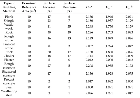
Another far-reaching implication of the surface ‘fractalization’ of building structures and materials is that they directly connect us to nature. To prove this, we examine bricks and wooden claddings, and we calculate the dimensions of cliffs or the natural scenes of forests as long as we regard them as ‘façades’. Of course, we could also fractalize rocks and trees in different, more classical, ways, e.g., by analyzing their geological structure or the set of branches and leaves, but we focus on their projected patterns herewith. Tables1and 2below contains the Hausdorff dimensions of some of our well-known building materials compared to the natural ‘scene’ that may either surround or make ground for our edifices.
Table 1. The Hausdorff dimensions of walls or claddings built from some well-known materials.
Surface measurements were made through the use of digital photography, image processing and metric data provided by manufacturers.
Type of Building Material
Examined Reference Area (m2)
Surface Increase
(%)
Surface Decrease
(%)
DH+ DH− DH±
Plank 10 17 6 2.136 1.946 2.091
Shingle 10 23 7 2.180 1.937 2.129
Wattle-
work 10 41 25 2.298 1.750 2.129
Rock 10 39 29 2.286 1.703 2.083
Rough
stone 10 16 13 2.129 1.879 2.026
Fine-cut
stone 10 8 3 2.067 1.974 2.042
Brick 10 20 17 2.158 1.838 2.026
Clinker 10 18 17 2.144 1.838 2.009
Plaster 10 5 0 2.042 2.000 2.042
Rough
concrete 10 27 5 2.208 1.955 2.173
Shuttered
concrete 10 17 8 2.136 1.928 2.075
Precast
concrete 10 2 2 2.017 1.982 2.000
Steel 10 0 1 2.000 1.991 1.991
Weathering
steel 10 3 1 2.026 1.991 2.017
Table 2.The Hausdorff dimensions of natural scenes surrounding a building or an object. Surface estimates were made through the use of digital photography, image processing and Google Earth data.
Type of Natural Scene
Extrapolated Reference Area (m2)
Surface Increase
(%)
Surface Decrease
(%)
DH+ DH− DH±
Clay wall 1000 23 5 2.060 1.985 2.048
Basalt wall 1000 45 8 2.108 1.976 2.091
Sedimentary
cliffs 1000 65 13 2.145 1.960 2.121
Reed
marsh 1000 45 23 2.108 1.924 2.058
Temperate
forest 1000 55 18 2.127 1.943 2.091
Buildings2021,11, 16 9 of 16
6. Two or Three Basic Design Trends (Results B)
In learning about the autonomy of façades, we cannot omit shedding light on a certain problem about their typology. Since the patterns could be shown as fractals even if the membrane has no real spatial extension, we also need to take planar decorations into account. It is no doubt that this will lead to our second formula resulting in fractals between 1D and 2D; however, this calculation would benefit a picturesque, atectonic, thus generally asymmetrical architecture. Instead, for numerical comparisons, it is more preferable to analyze tectonic examples, where there is a clear and logical connection between the structure and façade; therefore the appearance of self-similarity is not only visual but haptic [60].
History gives us plenty of examples for relief façades that are discernible by analyzing their ‘communicative’ layers [61]. The sole criterion for their selection may only be their composition of architectonic layers, as it has been explained through the case of Palladio’s Palazzo Valmarana. Instead of providing a complete list of buildings, we chose some of the most magnificent ones in history’s timeline in chronological order: Diocletian’s Palace in Split, the Durham Cathedral, Palazzo Strozzi in Florence, the Basilica of Andrea Palladio in Verona, Turin’s Palazzo Carignano by Guarino Guarini, the Bauakademie of Karl Friedrich Schinkel in Berlin, Adler and Sullivan’s Wainwright Building in St. Louis, Missouri, and Ljubljana’s National and University Library by Jože Pleˇcnik. New York’s Seagram Building of Mies van der Rohe and Philip Johnson might also be added to the circle, which seems a blatant exception at first sight, yet it is feasible for the proper comparisons.
Nonetheless, the other tradition of ‘drawn’ façades with no plausible connection between the structure and the building’s membrane also has a history. It goes back as far as Nero’s Domus Aurea and the ‘architectural revolution’ of Rome [62]—with the remark that it was also a masterpiece that summarized the knowledge of its predecessors.
The seemingly anachronistic projections of this glamorous ancient urban palace may be remembered by the façade of the Church of San Miniato al Monte in Florence, or by the stone cladding of the Dome of Santa Maria del Fiore itself, because they are essentially planar compositions. The list may be completed by historical palace interiors, and their painters’ ambition to create the illusion of open spaces, e.g., in the Villa Medici at Poggio a Caiano, the Versailles Castle, or the Nymphenburg Palace in Munich.
Finally, we could arrive at the realization that Otto Wagner’s Majolikahaus in Vi- enna had its important role in preparing the severe and unornamented architecture of the Looshaus, the redecoration of L’Aubette in Strassbourg by Theo van Doesburg, Sophie Taeuber-Arp and Jean Arp, or the Villa Stein at Garches, France, of Le Corbusier. If we regard them as the heirs of the planar tradition, we will not find the United Nations Head- quarters in New York essentially different from Michael Graves’ post-modern Portland Building box. After all, an ontological difference lies only between the organically and the indifferently or chaotically composed façades, and 20th century Modernism often indicates this difference [41].
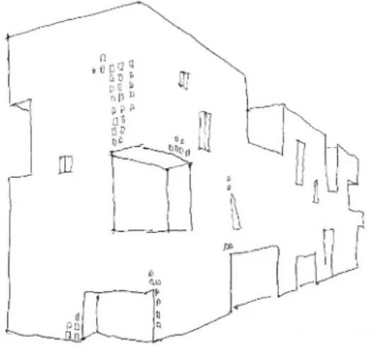
As a third but very rare case, we know of contemporary designs that were overtly inspired by fractals [7,63]. Among them, Steven Holl’s Stadgenoot Pavilion in Amster- dam and his Simmons Hall at the MIT Campus in Cambridge, MA, USA (see Figure4), are outstanding examples.
Buildings2021,11, 16 10 of 16
account. It is no doubt that this will lead to our second formula resulting in fractals between 1D and 2D; however, this calculation would benefit a picturesque, atectonic, thus generally asymmetrical architecture. Instead, for numerical comparisons, it is more preferable to analyze tectonic examples, where there is a clear and logical connection between the structure and façade; therefore the appearance of self‐similarity is not only visual but haptic [60].
History gives us plenty of examples for relief façades that are discernible by analyzing their ‘communicative’ layers [61]. The sole criterion for their selection may only be their composition of architectonic layers, as it has been explained through the case of Palladio’s Palazzo Valmarana. Instead of providing a complete list of buildings, we chose some of the most magnificent ones in history’s timeline in chronological order:
Diocletian’s Palace in Split, the Durham Cathedral, Palazzo Strozzi in Florence, the Basilica of Andrea Palladio in Verona, Turin’s Palazzo Carignano by Guarino Guarini, the Bauakademie of Karl Friedrich Schinkel in Berlin, Adler and Sullivan’s Wainwright Building in St. Louis, Missouri, and Ljubljana’s National and University Library by Jože Plečnik. New York’s Seagram Building of Mies van der Rohe and Philip Johnson might also be added to the circle, which seems a blatant exception at first sight, yet it is feasible for the proper comparisons.
Nonetheless, the other tradition of ‘drawn’ façades with no plausible connection between the structure and the building’s membrane also has a history. It goes back as far as Nero’s Domus Aurea and the ‘architectural revolution’ of Rome [62]—with the remark that it was also a masterpiece that summarized the knowledge of its predecessors. The seemingly anachronistic projections of this glamorous ancient urban palace may be remembered by the façade of the Church of San Miniato al Monte in Florence, or by the stone cladding of the Dome of Santa Maria del Fiore itself, because they are essentially planar compositions. The list may be completed by historical palace interiors, and their painters’ ambition to create the illusion of open spaces, e.g., in the Villa Medici at Poggio a Caiano, the Versailles Castle, or the Nymphenburg Palace in Munich.
Finally, we could arrive at the realization that Otto Wagner’s Majolikahaus in Vienna had its important role in preparing the severe and unornamented architecture of the Looshaus, the redecoration of L’Aubette in Strassbourg by Theo van Doesburg, Sophie Taeuber‐Arp and Jean Arp, or the Villa Stein at Garches, France, of Le Corbusier. If we regard them as the heirs of the planar tradition, we will not find the United Nations Headquarters in New York essentially different from Michael Graves’ post‐modern Portland Building box. After all, an ontological difference lies only between the organically and the indifferently or chaotically composed façades, and 20th century Modernism often indicates this difference [41].
As a third but very rare case, we know of contemporary designs that were overtly inspired by fractals [7,63]. Among them, Steven Holl’s Stadgenoot Pavilion in Amsterdam and his Simmons Hall at the MIT Campus in Cambridge, MA, USA (see Figure 4), are outstanding examples.
Figure 4. A perspective drawing of Steven Holl’s Simmons Hall at the MIT Campus in Cambridge, Massachusetts. A new epoch of fractal architecture has already started.
Figure 4.A perspective drawing of Steven Holl’s Simmons Hall at the MIT Campus in Cambridge, Massachusetts. A new epoch of fractal architecture has already started.
The latter is more than a metaphor of the Menger sponge, the Hausdorff dimension of which is ln20/ln3∼=2.727. The dimension of this building, therefore, should not be derived from its façades but its solid that is decreased by voids, similar to the case of urban blocks [64] (pp. 143–148). Hall’s buildings could be examined by the extrapolation of the second, orDH−formula described above.
Table3registers the Hausdorff dimensions of some highlighted buildings’ façades along the timeline of history, together with information regarding their type.
It showcases that the Hausdorff dimensions (bothDH− andDH±) calculated from certain 19th and 20th century façades have substantial regressions compared to their predecessors. This is mostly due to the loss of the material surface in exchange for sunlight and transparency. Before this dramatic change, the differences betweenDH+andDH−were more or less balanced, whereas during the late Renaissance and Baroque, the plasticism or the materiality of buildings (DH+) clearly increased thanks to the voluminous walls and elaborate details characteristic of the epoch. It is important to note that the mixed dimension (DH±) has typically been over 2.0 until it dropped in the 19th century, which proves that Historicism was involved in modern trends already, before the turn of the millennium. As a parallel tendency, modern elevations were hard to identify as fractals anymore; yet, notably from the late 20th century [63], a certain revival of organic surfaces has begun, notwithstanding the losses of social connectivity. This tendency continues after the turn of the millennium as indicated by the calculated values of the MIT Simmons Hall.
Buildings2021,11, 16 11 of 16
Table 3.The Hausdorff dimensions of the façades of some historical and contemporary buildings. Surface measurements were made through architectural plans, photography, and Google Earth data.
Building and
Location Century of Origin Location of Reference Layer
C. Area1of Reference Layer
(m2)
Surf. Incr. (%) Surf. Decr. (%) DH+ DH− DH±
Diocletian’s Pal.,
Split, Croatia 3th sea front 3000 13 14 2.031 1.962 1.997
Durham Cath.,
Durham, UK 11th north aisle 800 19 17 2.052 1.944 2.006
Pal. Strozzi,
Florence, Italy 15th east elevation 1000 16 13 2.043 1.960 2.009
Basilica Palladiana, Vicenza, Italy
16th south elevation 700 33 16 2.087 1.947 2.048
Pal. Valmarana,
Vicenza, Italy 16th west elevation 450 33 20 2.093 1.927 2.040
Pal. Carignano,
Turin, Italy 17th west elevation 2000 39 19 2.087 1.945 2.048
Bauakademie,
Berlin, Germany 19th north elevation 950 15 18 2.041 1.942 1.991
Wainwright Bldg.,
St. Luis, MO 19th south elevation 800 18 43 2.050 1.832 1.914
National Library,
Ljubljana, Slovenia 20th east elevation 900 23 11 2.061 1.966 2.033
Seagram Bldg.,
New York, NY 20th west elevation 6500 29 63 2.058 1.774 1.905
MIT Simmons Hall, Cambridge,
MA
21st south elevation 2500 67 44 2.131 1.852 2.053
1The projected area of the reference layer does not necessarily equal to the total projected area of the façade.
7. A Guide to Reproduce Our Numeric Results in Tables1–3
Our surface measurements were made through the use of digital photography, image processing, and metric data provided by manufacturers. To demonstrate the replicability of our numerical results, we detail our calculations regarding the Hausdorff dimensions of one of the building materials listed in Table1.
For easy understanding, we have chosen a clinker wall with a 10 m2 examined reference area. The visible side of the clinker elements have the dimensions 6.5 cm×25 cm, which gives the area of 162.5 cm2each. We consider the calculated surface relatively smooth; however, the joints between the elements decrease the total area of the sample wall by 1 cm×(1 cm + 6.5 cm + 25 cm), that is, 32.5 cm2per brick. Consequently, the replicated area is 195 cm2, which is decreased by 32.5 cm2. This technically means that the surface decreases by 16.67%, but because of the softness of the bricks’ edges, we round this value up to 17%. Calculating with the value of the examined reference area, Equation (3) will result in 1.838 as the amount forDH−.
On the other hand, joints have a certain depth, which adds hidden areas to the examined surface. Since we put this depth at 0.5 cm along the clinker edges, it means an additional 0.5 cm×2×(6.5 cm + 25 cm), that is, 31.5 cm2new surface area. Comparing with 195 cm2, the theoretical surface increase is 16.15%, but because of certain irregularities—e.g., the curvature of the mortar, or the varying position of the bricks versus the ideal vertical plane—this value grows at least by 2%. Following Equation (2), the rounded 18% of surface increase finally makesDH+= 2.144. From the unified Equation (4), the value 2.009 for DH±can be easily calculated. We can apply the same scheme to reproduce the Hausdorff dimensions of all the other building materials listed in Table1. Furthermore, we may examine new ones with more detailed specifications.
As alternatives, we may also use software to process 3D models from the data captured by laser scanners or digital cameras. Although the introduction of this software is not the concern of the current study, we feel obliged to refer to the revolutionary methods in either geography [54,55], monument preservation or museology [65], which have more or less the same principles. With the digital method, we can compute the total surface area of a relief, and compare that with the area of the relief’s planar projection. The proportion of the values will lead to the percentage of surface increase, thus toDH+, whereas all the proportion of ‘missing areas’ will affectDH−. In order to obtain the proper data for the latter, a reference plane must be set with an adjustable level of depth tolerance. The sum of the empty areas on the plane will decrease the overall surface of the processed image, so the percentage of decrease can be calculated.
The same method applies to the natural scenes, provided that they are considered as façades that possess a certain thickness. In the case of natural walls and cliffs, we can easily adapt the digital method to the geological morphs; however, the measurement of vegetation could be a greater challenge. For instance, the visual depth of a temperate forest is far greater than that of natural or manmade walls; therefore a ‘viewshed’ analysis [66] might be necessary to calculate itsDH+. To avoid this complication, we ‘compress’ the forest’s space into a relief, so that a vertical reference plane—with a certain depth tolerance—could be defined. The forest between the plane and the viewer is considered a layer composed of plastic elements, while the nature behind the plane is looked at as an image. BothDH+and DH−are calculated relative to the reference plane, which implies the comparability of this layer to that of an architectonic façade.
Looking back to our discussion about Palladio’s Palazzo Valmarana, Figure2serves either as a representation of the logic behind the ‘relief method’, or as a guide to replicate the calculations of Table3. We need to emphasize: our paper assumes that the architectonic layers have a certain depth, so their Hausdorff dimensions cannot be calculated without measuring the thickness of the façade’s elements. This data is hidden from our sight when we look at the two-dimensional drawings of the building’s elevations. The invisible surfaces can best be measured by means of architectural drawings, e.g., ground plans and sections, because usually the façades do not reveal them.
Buildings2021,11, 16 13 of 16
In the case of Palazzo Valmarana, we can choose among the three architectonic lay- ers [48] interpreted by Figure2to start calculations. Due to our previous arguments, layers are attached to scales; therefore, if we prefer layer 1, we need to take the depth of the great pilasters, the pediments and the cornicione into account. Because the area of the elements on this layer is relatively small, the hidden surfaces are responsible for a 33%
growth in area, causingDH+to reach the amount of 2.093, whereas the openings associated with the same layer take only 20% area away. Due to this slighter decrease, the joined Hausdorff dimension calculated from layer 1 equals to 2.048. It exceeds the amount of 2, which indicates the overall plasticity of the selected façade. We underline thatDH+can only be associated withDH−if we relate them to the same reference plane—most often the plane of the window frames—and calculate them by measuring the elements on the same scale, thus the same layer only. Our surface measurements of the buildings listed in Table3were made accordingly through the analysis of architectural plans, photography and Google Earth data. Photography and Google data was necessary to check if the actual buildings differed from the architectural plans.
8. Conclusions
Façades are communicative elements of architecture, which could be regarded as either reliefs or planar motifs that imply symmetry—and not in a trivial sense [56]. Self-similarity, as a type of symmetry, is a key quasi-feature of fractalized architectonic elevations if we do not require them to be fractals in a strict mathematical sense (not all the fractals are self- similar, anyway). Overlapping layers could be responsible for changes in the dimension of façades from the observer’s viewpoint, which is best described with the application of the Hausdorff–Besicovitch correlation. The investigation on the fractal dimension related to certain elevations, building materials, and natural scenes allows us to compare certain building membranes and show their compositional tendencies along a historical timeline.
The numerical amount of the Hausdorff dimension, however, does not signify spatial connectivity per se, since the latter is equally based on the level of similarity to the patterns that surround the building. DH in this case is a possible numeric determination of the genius loci—the ‘atmospheric’ phenomenon—which is our main purpose behind the comparison of the data findings listed in Tables1–3. These tables provide information about the mathematical similarities of natural scenes and building materials, and grant us a comparison between them and the architectonic façades (see Figure5).
Buildings 2021, 11, 16 12 of 15
In the case of Palazzo Valmarana, we can choose among the three architectonic layers [48] interpreted by Figure 2 to start calculations. Due to our previous arguments, layers are attached to scales; therefore, if we prefer layer 1, we need to take the depth of the great pilasters, the pediments and the cornicione into account. Because the area of the elements on this layer is relatively small, the hidden surfaces are responsible for a 33% growth in area, causing DH+ to reach the amount of 2.093, whereas the openings associated with the same layer take only 20% area away. Due to this slighter decrease, the joined Hausdorff dimension calculated from layer 1 equals to 2.048. It exceeds the amount of 2, which indicates the overall plasticity of the selected façade. We underline that DH+ can only be associated with DH− if we relate them to the same reference plane—most often the plane of the window frames—and calculate them by measuring the elements on the same scale, thus the same layer only. Our surface measurements of the buildings listed in Table 3 were made accordingly through the analysis of architectural plans, photography and Google Earth data. Photography and Google data was necessary to check if the actual buildings differed from the architectural plans.
8. Conclusions
Façades are communicative elements of architecture, which could be regarded as either reliefs or planar motifs that imply symmetry—and not in a trivial sense [56]. Self‐
similarity, as a type of symmetry, is a key quasi‐feature of fractalized architectonic elevations if we do not require them to be fractals in a strict mathematical sense (not all the fractals are self‐similar, anyway). Overlapping layers could be responsible for changes in the dimension of façades from the observer’s viewpoint, which is best described with the application of the Hausdorff–Besicovitch correlation. The investigation on the fractal dimension related to certain elevations, building materials, and natural scenes allows us to compare certain building membranes and show their compositional tendencies along a historical timeline.
The numerical amount of the Hausdorff dimension, however, does not signify spatial connectivity per se, since the latter is equally based on the level of similarity to the patterns that surround the building. DH in this case is a possible numeric determination of the genius loci—the ‘atmospheric’ phenomenon—which is our main purpose behind the comparison of the data findings listed in Tables 1–3. These tables provide information about the mathematical similarities of natural scenes and building materials, and grant us a comparison between them and the architectonic façades (see Figure 5).
Figure 5. The comparability of the patterns from different sources—architectonic façades, natural scenes, and textures of building materials—through their Hausdorff dimensions.
The built environment has always been more planar than nature. Yet we can conclude from the comparison of data set by Tables 1 and 2, that the more traditional the Figure 5.The comparability of the patterns from different sources—architectonic façades, natural scenes, and textures of building materials—through their Hausdorff dimensions.
The built environment has always been more planar than nature. Yet we can conclude from the comparison of data set by Tables1and2, that the more traditional the building material, the better it incorporates the plasticism of landforms and vegetation. The doctrine of architecture, after all, has been keeping our cities fundamentally different from our
primordial environment, but at the same time has exhibited a certain affinity for nature.
The fate of our living space may depend on how well we can reconnect to nature by means of reinventing building materials or relearning the classical rules of composition, balance and ratio. New design ideas could also be crucial to compensate us for the heavy loss of morphological complexity during the 20th century. The calculations behind some contemporary buildings reveal that harmony may not be restored without an extent of
‘sculptural’ overcompensation (see the calculated values of the MIT Simmons Hall in Table 3).
The future direction of this research promises to endorse a shift in scale where, instead of individual building membranes, more complex spatial dispositions of solids, voids and urban landscapes may be examined. This should be an attempt to integrate the patterns of connectivity with space syntax and urban morphology analyses for a comprising betterment of our built environment.
Funding:This research received no external funding.
Institutional Review Board Statement:Not applicable.
Informed Consent Statement: Informed consent was obtained from all subjects involved in the study.
Data Availability Statement: The data presented in this study are available on request from the corresponding author.
Acknowledgments: I would like to thank to Professor Nikos A. Salingaros for his invitation and friendly support during the preparations for this publication. I also thank to James Reese for proofreading. All the Figures are hand drawn by the author.
Conflicts of Interest:The author declares no conflict of interest involved in this article.
References
1. Frampton, K.Megaform as Urban Landscape; The University of Michigan A. Alfred Taubman College of Architecture + Urban Planning: Ann Arbor, MI, USA, 1999.
2. Katona, V. Reconsidering the Tectonic: On the sacred ambivalence of the tectonic in the light of Martin Heidegger and relevant theoretical studies on architecture.Per. Pol. Architect.2010,41, 19–25. [CrossRef]
3. Solà-Morales, I. Weak architecture. InDifferences: Topographies of Contemporary Architecture; Whiting, S., Ed.; MIT Press: Cambridge, MA, USA, 1996; pp. 57–72.
4. Ceferin, P. Far from home: Contemporary Slovenian architecture in the making. Inˇ Architecture and Identity; Herrle, P., Wegerhoff, E., Eds.; LIT Verlag: Berlin, Germany, 2008; pp. 47–56.
5. Moore, S.A. Technology place and the nonmodern thesis.J. Architect. Edu.2001,54, 130–139. [CrossRef]
6. Rubin, E.Insuring the City: The Prudential Center and the Postwar Urban Landscape; Yale University Press: New Haven, CT, USA, 2012.
7. Ekino ˘glu, H. From design patterns to design machines: Will the robots take over architecture? Symmetry Cult. Sci. 2020, 31, 383–399. [CrossRef]
8. Gruson, F. The spirit and the symbol in architecture: The divine proportion.Symmetry Cult. Sci.2019,30, 5–14. [CrossRef]
9. Lefas, L. The strict and the broad sense of symmetry in Vitruvius’ De Architectura. Symmetry Cult. Sci. 2018,29, 353–363.
[CrossRef]
10. Salingaros, N.A. Applications of the golden mean to architecture.Symmetry Cult. Sci.2018,29, 329–351. [CrossRef]
11. Frampton, K. Towards a critical regionalism: Six points for an architecture of resistance. InThe Anti-Aesthetic: Essays on PostModern Culture; Foster, H., Ed.; Bay Press: Port Townsend, WA, USA, 1983; pp. 16–30.
12. Norberg-Schulz, C. The Phenomenon of Place. InTheorizing A New Agenda for Architecture: An Anthology of Architectural Theory 1965–1995; Nesbitt, K., Ed.; Princeton Architectural Press: New York, NY, USA, 1996; pp. 414–428.
13. Frascari, M. The tell-the-tale detail. InTheorizing A New Agenda for Architecture: An Anthology of Architectural Theory 1965–1995;
Nesbitt, K., Ed.; Princeton Architectural Press: New York, NY, USA, 1996; pp. 500–514.
14. Semper, G. Die Textile Kunst für sich betrachtet und in Beziehung zur Baukunst. InDer Stil in Den Technischen und Tektonischen Künsten Oder Praktische Aesthetik: Ein Handbuch für Techniker, Künstler und Kunstfreunde; Piel, F., Ed.; Mäander Kunstverlag:
Mittenwald, Germany, 1977; pp. 227, 229–234.
15. Frampton, K. Rappelàl’ordre: The case for the tectonic. InTheorizing A New Agenda for Architecture: An Anthology of Architectural Theory 1965–1995; Nesbitt, K., Ed.; Princeton Architectural Press: New York, NY, USA, 1996; pp. 516–528.
16. Rowe, C.; Slutzky, R. Transparency: Literal and Phenomenal.Perspecta1963,8, 45–54. [CrossRef]