IOP Conference Series: Materials Science and Engineering
PAPER • OPEN ACCESS
Development and characterization of innovative biopolymer foams
To cite this article: K Litauszki and Á Kmetty 2018 IOP Conf. Ser.: Mater. Sci. Eng. 426 012031
View the article online for updates and enhancements.
This content was downloaded from IP address 152.66.35.17 on 14/12/2018 at 09:40
1234567890‘’“”
11th Hungarian Conference on Materials Science IOP Publishing
IOP Conf. Series: Materials Science and Engineering 426 (2018) 012031 doi:10.1088/1757-899X/426/1/012031
Development and characterization of innovative biopolymer foams
K Litauszki1 and Á Kmetty1, 2
1 Budapest University of Technology and Economics, Faculty of Mechanical Engineering, Department of Polymer Engineering, Budapest, Hungary
2 MTA–BME Research Group for Composite Science and Technology, Budapest, Hungary
E-mail: litauszkik@pt.bme.hu, kmetty@pt.bme.hu
Abstract. Our development goal was to create foamed polymer systems based on biodegradable and renewable resource-based polymers. We used polylactic acid (PLA) and several types of chemical foaming agents (endothermic and exothermic), and produced foam samples by extrusion. We characterized and analyzed the foam samples with a wide range of tests (determining the cell structure, void fraction, compressive strength, etc.). Based on our tests, we showed the difference between the foaming agents and produced PLA-based foams with a void fraction of 57%.
1. Introduction
Today, with fast industrial development and rapidly increasing consumption, the need for packaging materials is increasing drastically. Most packaging is required by the food industry and the production of durable goods. The majority of these packaging materials, however, are one-way (single-use) packaging materials. The total production of the plastic industry was 322 million tonnes in 2015, and 58 million tonnes in the European Union, a major part of which – 39.9% – was packaging industry products.
At present, these products are made from petroleum-based polymers, typically polypropylene, polyethylene and polystyrene. At the end of their lifetime, disposing of them presents a major problem since they are not biodegradable.
Based on the latest trends, poly(lactic acid) (PLA) is one of the strongest biopolymer candidates to replace petroleum-based polymers [1]. Bio-based and biodegradable PLA in a foamed structure can provide a possible marketable solution for engineering and costumer needs. There are various existing foaming techniques, like extrusion foaming [2], injection foaming, bead foaming [3] and syntactic foaming techniques are also [4,5]. Although the numerous article regarding PLA foams, there was no investigation regarding comparison the effect of endothermic and exothermic CBA effect on the PLA foaming behaviour in case of continuous extrusion foamed final product.
In this article we present the application of different types of Chemical Blowing Agents (CBA) to produce foamed PLA based biopolymer structures via extrusion to characterise the resulting foam structures in correlation of the CBAs endothermic or exothermic nature. The matrix polymer was PLA (foaming grade). We chose foaming agents according to the literature, and the manufacturer’s information and recommendations. We used exothermic and endothermic CBAs. Extrusion was carried
2
1234567890‘’“”
11th Hungarian Conference on Materials Science IOP Publishing
IOP Conf. Series: Materials Science and Engineering 426 (2018) 012031 doi:10.1088/1757-899X/426/1/012031
out on a twin-screw extruder. Each formulation contained 98m% PLA and 2m% blowing agent, and was produced with the same temperature profile, screw speed, and melt temperature. We investigated the resulting foamed products with a scanning electron microscope, and differential scanning calorimetry, cell-population and density measurements and compression tests to reveal and present the differences between endothermic and exothermic types of CBA.
2. Experimental 2.1. Materials
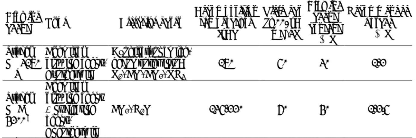
A commercial grade of linear polylactic acid (Ingeo™ Biopolymer 8052D, NatureWorks© LLC, USA) was used as polymer matrix, in granule form. The D-lactide content of this PLA was 4.5 mol% [6]. Its density was 1.24 g/cm3, its glass transition temperature was 60.2 °C, its crystalline melting temperature was 153.3 °C, and its fraction of crystallinity before processing was 36.1%, which were measured by the authors. Two types of chemical blowing agents (CBA) were used, one exothermic (Tracel IM 3170 MS, Tramaco GmbH) and one endothermic (Tracel IMC 4200, Tramaco GmbH). Both foaming agents were in granule form and contained a polymeric carrier. Characteristic properties of foaming agents can be found in Table 1.
Table 1. Characteristic properties of foaming agents, according to product technical datasheet
Blowing
agent Type Effective gases
Decomposition temperature
[°C]
Yield gas at 220°C [mL/g]
Blowing agent content
[%]
Recommended dosage
[%]
Tracel IM 3170 MS
Chemical blowing agent, Exothermic
Azodicarbonamide, decomposes into:
N2, CO, CO2, NH3
170 50 30 1-2
Tracel IMC 4200 a
Chemical blowing agent + nucleating agent, Endothermic
CO2, H2O 135-220 60 40 1-2.5
a The active ingredients of the CBA are probably sodium bicarbonate and citric acid
Table 2. Notation for the experiment formulations
Notation type of PLA Name of CBA Type of CBA Dosage of CBA [m%]
8052 Ingeo 8052D - - -
8052_3170 Ingeo 8052D Tracel IM 3170 MS (exothermic) 2 8052_4200 Ingeo 8052D Tracel IMC 4200 (endothermic) 2
2.2. Material processing
Prior to manufacturing, the PLA granules were dried at 80°C for 6 hours in a WGL-45 drying oven.
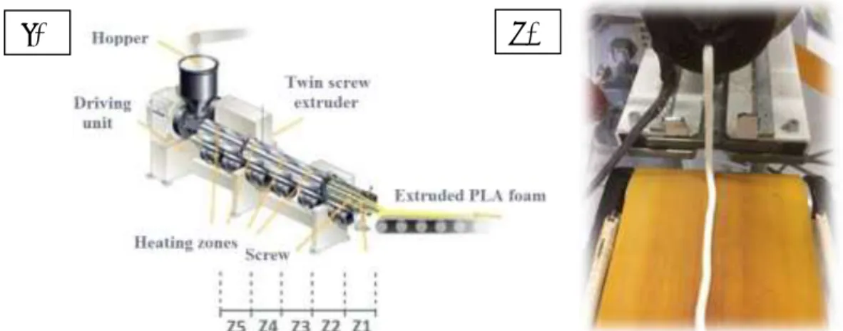
Before manufacturing, a fixed amount of chemical foaming agents was added by dry mixing to the poly(lactic-acid) at a rate of 2 m%, which resulted in a homogeneous mixture The extrusion chemical foaming process was performed with a Teach-line ZK25T twin-screw extruder produced by Collin GmbH (Figure 1.). The formulations and their notation can be found in Table 2. The temperature profile of the extruder was 155/165/175/190/190 °C; we used an increasing temperature profile, where zone 5 (Z5) is the temperature of the extruder die. The pressure and temperature of the melt were monitored
1234567890‘’“”
11th Hungarian Conference on Materials Science IOP Publishing
IOP Conf. Series: Materials Science and Engineering 426 (2018) 012031 doi:10.1088/1757-899X/426/1/012031
and registered. The rotation speed of the screw was 10 rpm. The extrusion die was a cord type with a circular cross-section, and with a nominal diameter of 3 mm.
Figure 1. a) Extruder assembly used during the chemical foaming of poly(lactic-acid), b) foam extrusion
3. Methods of analysis 3.1. Thermal analysis
Differential scanning calorimetry (DSC) measurements were performed with a TA Instruments Q2000 automatic sampling device. The measurement temperature range was 0-200 °C, the heating rate was 5 °C/min, the mass of the samples was between 3 mg and 6 mg, and the tests were performed in nitrogen protective gas (20 ml/min) and with a nitrogen measuring atmosphere (20 ml/min). The degree of crystallinity (𝑐) was calculated according to Equation 1, where 𝐻𝑚 is the melt and 𝐻𝑐 is the crystallization enthalpies. PLA100% is the theoretical melting enthalpy of 100% crystalline PLA, which is 93 J/g [7].
𝑐 =𝐻𝑚−|𝐻𝑐|
𝑃𝐿𝐴100% ∗ 100 [%] (1)
3.2. Characterisation of biopolymer foam structures
The SEM images were produced with a JEOL JSM 6380LA scanning electron microscope with an acceleration voltage of 10 kV. The surfaces of the samples were gold plated in vacuum (Argon gas flush, 15 mA/Pa).
The volume of foam structures was measured with a 50 ml glass cylinder (accuracy 0.1 cm3); the measuring medium was distilled water. Mass was measured with a Sartorius BP121S type balance. Its range is 120 g, its measuring accuracy is 0.1 mg and its resolution is 0.1 mg. Density was calculated according to Equation 2.
𝜌𝑓𝑜𝑎𝑚=𝑚𝑉𝑓𝑜𝑎𝑚
𝑓𝑜𝑎𝑚
(2)
Cell population density was calculated based on the SEM images, according to Eq. 3, where n [-] is the number of cells counted in the recorded image, A [mm2] is the cross section area of the sample, M [-] is magnification and Vf [-] is the void fraction. [6, 8]
Nc= (n∗M2
A )
3 2∗ 1
1−Vf (3)
a) b)
4
1234567890‘’“”
11th Hungarian Conference on Materials Science IOP Publishing
IOP Conf. Series: Materials Science and Engineering 426 (2018) 012031 doi:10.1088/1757-899X/426/1/012031
This method not only takes into consideration the magnification applied, but corrects the density of the cell population with the expansion ratio, as well. The values thus calculated can be used to classify the relationships between processing and the foamed cell structure [6]. The expansion ratio can be calculated with Equation 4, where ER is the rate of expansion, ρrel is relative density and Vf is the void fraction [9].
𝐸𝑅 =𝜌1
𝑟𝑒𝑙=1−𝑉1
𝑓 (4)
3.3. Mechanical characterisation
Foam compressive strength tests were performed with a Zwick Z005 universal testing machine in compression mode. The load cell was a Mess & Regeltechnik KAP-TC type cell. Its range is 0-5000 N, the preload applied was 1 N. The measurement speed was 2 mm/min. The test piece was cylindrical, with a diameter of 3 mm and a height of 10 mm. The test was continued until a deformation of 10% was reached. Foam compressive strength was calculated with Eq. 5.
compressive strength = 𝐹10%
𝐴𝑓𝑜𝑎𝑚 (5)
4. Results and discussion 4.1. Foam processing
During foam extrusion, temperature was kept constant in the case of both formulations (195 °C ± 1 °C).
Manufacturing parameters were also constant (within a range of ± 2 °C) except for melt pressure (Table 3.). The extrusion parameters can be found in Table 3. Melt pressure was 43 bar without a CBA. When a foaming agent was used, a drop in melt pressure can be observed, regardless of the type of CBA. The lowest melt pressure, 13 bar, was in the case of the 8052_4200 formulation with endothermic CBA, which is a 70% pressure drop (pmelt) compared to the reference PLA. A possible cause is that the decomposition products of Tracel IMC 4200 include CO2 and H2O, therefore the PLA was likely hydrolysed and its melt strength was reduced. In the case of the 8052_3170 formulation with the exothermic CBA, the pressure drop of the melt is 51%, which is a not drastic reduction.
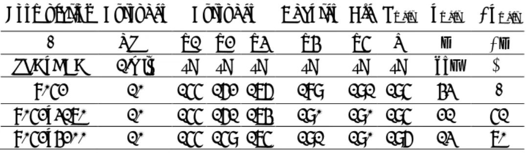
Table 3. Manufacturing parameters registered during extrusion Formulation Extruder Extruder Adapter Die Tmelt pmelt pmelt
- RPM Z1 Z2 Z3 Z4 Z5 T p p
PLA_CBA 1/min °C °C °C °C °C °C bar %
8052 10 155 162 176 189 191 195 43 -
8052_3170 10 155 161 174 190 190 195 21 51 8052_4200 10 155 159 175 191 190 196 13 70 4.2. Morphological structure of foams
We calculated the number of cells formed along the cross section, based on the SEM images (Figure 2.
- Figure 3.), and calculated cell population density. Then density was measured and void fraction was calculated. The resulting morphological structure was characterised by differential scanning calorimetry (DSC), then foam compressive strength was measured. The equipment and methods used for the measurements are presented in Chapter 3.
1234567890‘’“”
11th Hungarian Conference on Materials Science IOP Publishing
IOP Conf. Series: Materials Science and Engineering 426 (2018) 012031 doi:10.1088/1757-899X/426/1/012031
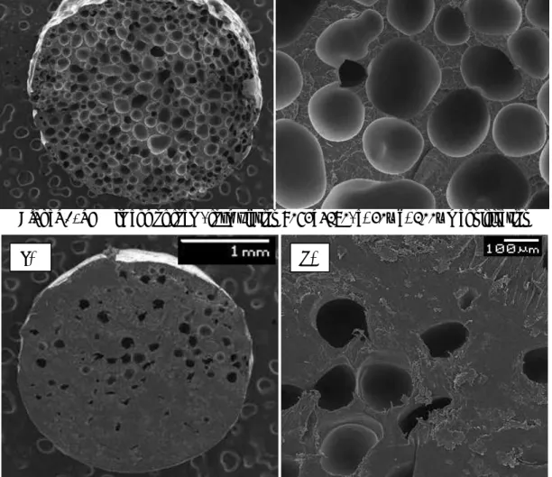
Figure 2. SEM image of foam, formulation 8052_3170, a) 20x b) 100x magnification
Figure 3. SEM image of foam, formulation 8052_4200, a) 20x and b) 100x magnification Cell population density
Cell population density was calculated based on SEM images (Figure 2. - Figure 3.). Based on the results, the most promising foaming agent is Tracel IMC 3170. The unoptimized manufacturing production experiment resulted in a cell population density of 4.82 – 5.61x10⁵/cm3. These values are somewhat lower than the values of the foam structures produced by Julien et al. [10] (7.38 - 10.86x10⁵), but they used an endothermic CBA (Hydrocerol OMAN698483), which product contains a nucleating agent. Mautana et al. [9] were able to approach 106 cells/cm3 with an optimized temperature profile, extruder speed and using 0.5-1.5% of an endothermic CBA.
Density
The results of density measurements (Table 4.) correlate well with the results expected based on the SEM images. The neat, unfoamed material (Ingeo 8052D) has a density of 1.24 g/cm3 and the lowest mass reduction was experienced with the 8052_4200 formulation. In the case of the 8052_3170 formulation, the decrease in density was 57%. The values are typical in the case of foaming thermoplastic polymers [10], but these values go beyond the values for the chemical foaming of PLA described in the literature [7–10].
b) a)
b) a)
6
1234567890‘’“”
11th Hungarian Conference on Materials Science IOP Publishing
IOP Conf. Series: Materials Science and Engineering 426 (2018) 012031 doi:10.1088/1757-899X/426/1/012031
Table 4. Density and void fraction, and cell population density (calculated from SEM images) of foam structures
Sample Density [g/cm3] Void fraction [%] Cell population density [cell/cm3]
8052_3170 0.53 57.6 4.82E+05
8052_4200 1.00 19.1 5.58E+04
We investigated commercially available polylactic acid (in granular form) as well as the structure of the PLA after extrusion and the structure of foams formed by chemical foaming (Table 5.).
Table 5. DSC curves of different PLA samples and PLA foams, 1st heating up PLA
type
CBA type
CBA [wt%]
Tg
[°C]
Tcc
[°C]
Hcc
[J/g]
Tm1
[°C]
Tm2
[°C]
Hm
[J/g]
c [%]
total
[%]
8052D - - 60.2 - - 153.3 36.4 36.1 36.1
8052D
(ext) - - 60.2 115.9 25.2 150.3 154.1 28.8 3.9 31.0
8052D 3170
(exo) 2.0 59.6 107.5 28.5 147.6 154.8 31.4 3.1 33.8 8052D 4200
(endo) 2.0 61.2 107.9 28.6 147.6 154.9 30.5 2.1 32.8
Figure 4. a) DSC curves of PLA granules, extruded PLA and the produced foam structures (1st heating up)
Figure 4. shows that that the commercially available (partially crystalline) PLA granule (8052) does not have an exothermic peak caused by cold crystallisation, but it appears in the case of the processed PLA (8052_1x ext) and chemically foamed samples. This is due to the fact that after processing the crystalline fraction cannot be formed because rapid (air) cooling leaves no time for the molecular chains to form ordered, crystalline regions. During the DSC measurement, the molecular chains are able to become more ordered, which is accompanied by heat release. These crystalline regions later melt at a higher temperature and the polymer melts. In case of the extruded (unfoamed and foamed) samples, the end of the cold crystallization process and the beginning of the melting process of the crystalline segments
0 20 40 60 80 100 120 140 160 180 200
Heat flow [mW/g]
Temperature [ C]
8052_3170 8052_4200 8052 8052_1x ext
1234567890‘’“”
11th Hungarian Conference on Materials Science IOP Publishing
IOP Conf. Series: Materials Science and Engineering 426 (2018) 012031 doi:10.1088/1757-899X/426/1/012031
occur simultaneously and there is a sloping baseline between the two phenomena instead of a horizontal baseline.
It is interesting that there are two crystalline melting peaks. Unlike the original granules, a second crystalline phase was formed with a lower crystal melting temperature after processing (8052D_ext) and in foam structures. Frackowiak et al. [13] explained the phenomenon with the fact that the α’ crystals of the lower temperature are smaller and were formed during the cold crystallization process, whereas the α crystal types having a higher melt temperature were formed during the primary crystallization process, therefore they can be connected to the technology in the present case [14]. Based on this, it can be stated that foaming agents affect the crystalline structure of the polymer.
It can be noticed that after processing (compared to the reference PLA) only 3.9% crystalline part can form after rapid cooling. The unprocessed granules, however, have a crystalline fraction of 36%.
Foaming further reduced the crystalline fraction, although only to a small extent.
4.3. Microscopic structure of foams
The comparison of 20x magnification SEM images (Figure 2.-Figure 3.) clearly shows that the foam structure produced by the Tracel IMC 4200 is not suitable either from the point of view of cell nucleation or cell growth. This is a visible consequence of the hydrolysis process described in section 4.1., which occurs during production. The best performing foaming agent is Tracel IM 3170. The foam produced with this CBA contains a considerable amount of cells and the cells formed were able to grow, thereby enhancing the rate of expansion. Although the shape and location of the cells do not make the structure completely homogeneous, but still, Tracel IM 3170 MS is a promising foaming agent in contrast to Tracel IMC 4200.
4.4. Mechanical characterisation
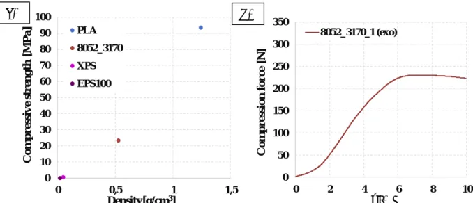
Figure 5. a) shows that a foam structure of a compressive strength of nearly 25 MPa was created with a significant reduction of density (57%), compared to the original PLA. The figure also shows two variants (XPS and EPS100) of one of the most widely used foams, polystyrene foam.
Figure 5. a) Compressive strength of the manufactured foam structure as a function of density (EPS - Expanded polystyrene foam. XPS-Extruded polystyrene foam). b) Compression force-deformation (ε)
diagram in case of formulation 8052_3170 5. Conclusions
We performed several tests on the foam products in order to characterize them. Their density and void fraction were measured, then their structure and cell population density characterized based on SEM
0 10 20 30 40 50 60 70 80 90 100
0 0,5 1 1,5
Compressive strength [MPa]
Density[g/cm3] PLA
8052_3170 XPS EPS100
0 50 100 150 200 250 300 350
0 2 4 6 8 10
Compression force [N]
ɛ [%]
8052_3170_1 (exo)
a) b)
8
1234567890‘’“”
11th Hungarian Conference on Materials Science IOP Publishing
IOP Conf. Series: Materials Science and Engineering 426 (2018) 012031 doi:10.1088/1757-899X/426/1/012031
images, and their morphological characteristics were measured by DSC. Finally, their compression strength was measured with a universal testing machine.
In the case of the exothermic Tracel IM 3170 MS, a foam was formed and the reduction of its density was significant (57%). A proper cell structure developed without any technological optimization. In the case of the endodermic Tracel IMC 4200 foaming agent, the foam structure was not adequate. During the extrusion process, water was also formed as a decomposition product of the CBA, which very probably hydrolysed the polymer chains, thereby reducing the strength of the polymer melt. Its density decreased slightly compared to the neat, unfoamed polylactic acid and relatively few cells developed.
Acknowledgements
SUPPORTED BY THE ÚNKP-17-4-IIINEW NATIONAL EXCELLENCE PROGRAM OF THE MINISTRY OF HUMAN CAPACITIES. “PROJECTFINANCEDFROMTHENRDIFUNDTHE NATIONAL RESEARCH, DEVELOPMENT AND
INNOVATION OFFICE (NVKP_16-1-2016-0012).”
References
[1] Avérous L 2013 Handbook of Biopolymers and Biodegradable Plastics ed S Ebnesajjad (Oxford: Plastics Design Library)
[2] Bocz K, Tábi T, Vadas D, Sauceau M, Fages J and Marosi G 2016 Characterisation of natural fibre reinforced PLA foams prepared by supercritical CO2 assisted extrusion Express Polym.
Lett. 10 3144
[3] Nofar M and Park C B 2014 Poly (lactic acid) foaming Prog. Polym. Sci. 39 1721–41 [4] Katona B and Orbulov I N 2017 Structural Damages in Syntactic Metal Foams Caused by
Monotone or Cyclic Compression Period. Polytech. Mech. Eng. 61 146–52
[5] Al F, Huang Y, Naguib H E and Lo J 2016 Relation of impact strength to the microstructure of functionally graded porous structures of acrylonitrile butadiene styrene (ABS) foamed by thermally activated microspheres Polymer (Guildf). 98 270–81
[6] Ding W, Chu R K M, Mark L H, Park C B and Sain M 2015 Non-isothermal crystallization behaviors of poly(lactic acid)/cellulose nanofiber composites in the presence of CO2 Eur.
Polym. J. 71 231–47
[7] Fisher E, Sterzel H and Wegner G 1973 Investigation of the structure of solution growth crystals of lactide copolymers by means of chemical reactions Kolloid- Zug Polym. 251 980–
90
[8] Park C B 1993 Ther role of polyimer/gas solution in continuous processing of microcellular polymers (Massachusetts Institute of Technology)
[9] Matuana L M, Faruk O and Diaz C A 2009 Cell morphology of extrusion foamed poly(lactic acid) using endothermic chemical foaming agent Bioresour. Technol. 100 5947–54
[10] Julien J, Bénézet J, Lafranche E, Quantin J, Bergeret A and Lacrampe M 2012 Development of poly ( lactic acid ) cellular materials : Physical and morphological characterizations Polymer (Guildf). 53 5885–95
[11] Julien J M, Quantin J C, Bénézet J C, Bergeret A, Lacrampe M F and Krawczak P 2015
Chemical foaming extrusion of poly(lactic acid) with chain-extenders: Physical and morphological characterizations Eur. Polym. J. 67 40–9
[12] Ludwiczak J and Kozlowski M 2015 Foaming of Polylactide in the Presence of Chain Extender J. Polym. Environ. 23 137–42
[13] Frackowiak S, Ludwiczak J, Leluk K, Orzechowski K and Kozlowski M 2015 Foamed poly ( lactic acid ) composites with carbonaceous fillers for electromagnetic shielding J. Mater. 65 749–56
[14] Tábi T, Hajba S and Kovács J G 2016 Effect of crystalline forms (α’ and α) of poly(lactic acid) on its mechanical, thermo-mechanical, heat deflection temperature and creep properties Eur.
Polym. J. 82 232–43
![Table 5. DSC curves of different PLA samples and PLA foams, 1 st heating up PLA type CBA type CBA [wt%] T g [°C] T cc [°C] H cc [J/g] T m1 [°C] T m2 [°C] H m [J/g] c [%] total [%] 8052D - - 60.2 - - 153.3 36.4 36.1 36.1](https://thumb-eu.123doks.com/thumbv2/9dokorg/1407966.118605/7.892.137.771.399.910/table-dsc-curves-different-samples-foams-heating-total.webp)