DOI: 10.1556/606.2019.14.2.14 Vol. 14, No. 2, pp. 155–168 (2019) www.akademiai.com
INVESTIGATING THE EFFECT OF FAR AND NEAR FIELD TO FAULT ON SEISMIC BEHAVIOR OF DUAL FRAMES WITH CONVERGENT BRACING
EQUIPPED WITH VISCOSE DAMPER
1 Peyman BEIRANVAND*, 2 Hamidreza BABAALI, 3 Majid POURAMINIAN
1 Department of Civil Engineering, Lorestan University, Khorramabad, Iran e-mail: peyman51471366@gmail.com
2 Department of Civil Engineering, Khorramabad Branch, Islamic Azad University Khorramabad, Iran, e-mail: h-babaali @khoiau.ac.ir
3 Department of Civil Engineering, Ramsar Branch, Islamic Azad University, Ramsar, Iran e-mail: majid.pouraminian@gmail.com
Received 13 January 2019; accepted 25 March 2019
Abstract: In this study, non-linear behavior of steel frames with dual lateral loader system with convergent crossing and chevron bracing equipped with linear and non-linear liquid viscose dampers in 8 and 12 story models as 2D under the record of near and far field to fault earthquakes are studied, evaluated and compared. For doing time history non-linear analyses, non-linear analysis software of Perform-3D has been used. This research absolutely confirms that viscose dampers reduces structure’s responses under the effect of near and far field to fault records in a way that using non-linear viscose dampers in dual steel frames, the rate of created reduction is under the effect of near field records and more.
Keywords: Convergent dual frame, Viscose damper, Far field from fault, Near field to fault, Time history non-linear analysis, Convergent bracing
1. Introduction
The occurrence of big earthquakes and their life and financial damages especially in urban and rural populated areas discusses an important issue that must be applied in regulation and that is the effects of site’s closeness to seismic fountains (earthquake core). This subject is known in all developed countries around the world as Japan, America as new problem of designing resistant structures against earthquakes. Created damages in recent earthquakes in many countries represents the lack of consideration these effects in these countries’ designing regulations.
*
Today, controlling entry vibration to structure and its response, have created main changes in usual trend of designing and building resistant structures against earthquake.
In this thought, instead of building resistant structure against earthquake as the only solution, some side tools and facilities are installed on structure to behave with structure and they resist with structure as a set against earthquake. These facilities cause improving structure’s response at the time of earthquake through their particular behavior. Structures’ vibration control systems that are designed and installed for improving response and controlling the destruction of structure are divided into two categories of active and inactive. The goal of these methods is increasing structures’
safety in intense earthquakes and reducing structural and non-structural damages on them in average earthquakes and generally achieving their ideal performance. In one of these kinds of methods, viscose property and energy waste of some liquids for increasing structure’s efficiency against earthquake has been used that viscose dampers system can be mentioned as one of them. Using this system, entered energy to structure is attracted by these instruments and is wasted through a special process that is derived from passing viscose liquid from existing penetrations in system [1], [2].
1.1. Introducing viscose dampers
Viscose dampers were first used as shocks attractors in defense and aerospace industries. In Fig. 1 and Fig. 2 a view of viscose damper has been shown. Viscose dampers are widely used for seismic functions as resistant structures against earthquake or existing structures’ strengthening [3]. In earthquake occurrence, this kind of damper works and converts entered seismic energy to heat and waste it. These kinds of dampers after installations don’t need caring [4].
Fig. 1. The Maxwell model Fig. 2. The fluid viscose damper
These kinds of dampers are used in this study in steel dual frames and these frames are modeled and analyzed using structure analysis software Perform 3D [5]. There are some studies by Macris and Constantine and Constantine and Symans for achieving an accurate mathematical model for viscose dampers [6], [7]. The best prediction for behavior of viscose dampers is done using Maxwell model that is shown in Fig. 2. This model can be stated using below equation:
( )
dtdu dt
c du t
p 0 sgn
α
= . (1)
In this equation α is positive real power that varies from 0.1 to 2 that this value limits to structural function to 0.3 to 1. The symbol of ‘sgn’ is also the function of sign.
When α is equal to 1, Eq. (1) is used for linear dampers and for other values α introduces non-linear dampers. In this study considering strike pulses, α=0.5 is considered in most of records. Other values of α can be obtained from changing the form of apertures that will change the characteristics of liquid flow as well.
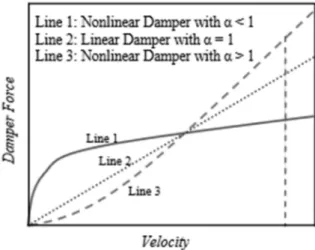
The relationship of force-velocity for linear and non-linear dampers is shown in Fig. 3. In this article, designed dampers by Tailor have been used that their characteristics are represented in Table I. These dampers are selected in accordance with the number of stories and their weights.
Fig. 3. Relationship between power and speed in the viscous liquid dampers
Table I
Specification of used viscous dampers in the models
Floor count FD(kN) Dmax(mm) Vmax(mm/s) C (kN.s/mm)
8 254 75 518 0.473
12 680 50 254 2.68
By combining dual frames systems with convergent bracings with linear and non- linear viscose dampers with power of attenuation percentage component equal to 0.5, responses in these models are investigated in this study.
1.2. Dynamic statement of problem
If structure is assumed as single degree of freedom systems, from structure dynamic it will have the system equation as:
( )
t F kx x c xm..+ .+ = . (2)
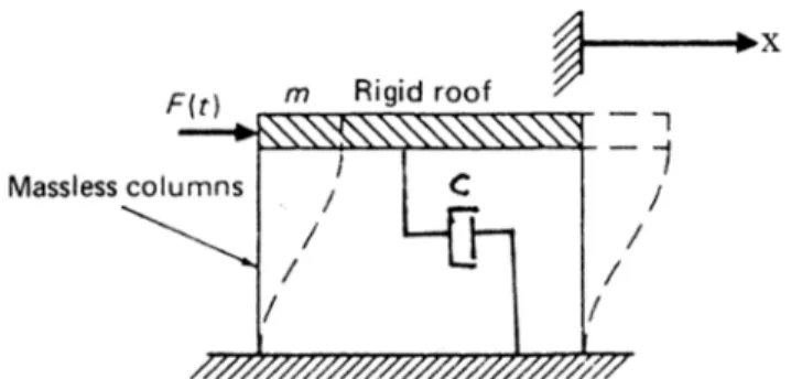
Fig. 4 shows a one-story building, which may be modeled with one degree of freedom. The model represented in this figure contains the following elements: (1) the concentrated mass m; (2) the lateral stiffness indicated by the coefficient k; (3) the damping in the system represented by coefficient c; and (4) the external force F(t) (considered to be a function of time); the response is indicated by the lateral displacement x(t) of the mass m.
Fig. 4. Mathematical model for one-story structure excited by an external force
In a very general attitude, recent system is affected by earth acceleration xg ..
in earthquake. In this mode inertial forces are stated as m(..x+..xg) and Eq. (2) will be as following:
xg m kx x c x
m..+ .+ =− .. . (3)
With a little attention in this equation and generalizing it to other structures it will get that whatever ..xg gets higher value, for making balance, system’s acceleration x..g will also increase that is a destructive phenomenon in structure so for preventing this problem, through changing the coefficients of c, m and k, Eq. (2)’s balance should be established. Since the mass exists in both sides of this equation so its decreasing or increasing does not play any roles in balance of equation so through two below methods, the balance of equation can be made:
A. Increasing system’s hardness (k): in this method, with adding hardening members as bracing or with increasing the level of members’ section, increase the hardness of system;
B. Increasing system’s attenuation (c): in this mode system’s attenuation can be increased through using damper.
In order to making balance in Eq. (3), for increasing hardness, bending frame and bracing combination and for increasing attenuation, viscose dampers have been used.
2. Modeling and accuracy
2.1. Linear and non-linear modeling
In this study, in order to investigate the effect of linear and non-linear viscose dampers on dual steel frames system seismic behavior with convergent bracings, two frames of 8, 12 stories have been designed with the number of craters equal with 4 with width of 5 m and height of 3.2 m. Considering the resistance system duality against lateral loads, designing these frames has been done based on Iran’s 2800 standard [8].
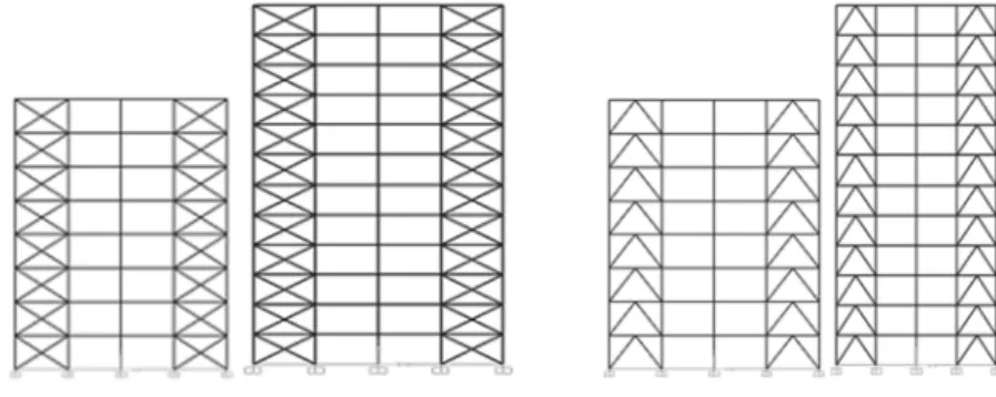
Based on this note, instead of distributing load to ratio of lateral loader elements rigidity in buildings with dual systems with braced frames, 100 percent of lateral power of earthquake can be applied to braces and eliminate comparing the rigidity of lateral loader elements only under the condition that frames be capable of 25 percent of lateral force [8]. These frames and their sections’ characteristics have been proposed in Fig. 5 and Fig. 6. Whole story in each one of models was determined as 400 kN and the weight of roof as 300 kN. Dual frame system consisting average steel bending frame + steel convergent bracing with behavior coefficient 7 were used for coping lateral loads [9].
Fig. 5. A view of 8 and 12 story models Fig. 6. A view of 8 and 12 story model After designing models based on equivalent static method, they were modeled for one more time in Perform 3D non-linear analysis software. The most important part of modeling section in this software is defining elements of beam, column, bracing and damper. For defining these characteristics, existing constructions seismic improving instructions as well as FEMA 356 have been used [10]. In Fig. 7 the installation of viscose damper has been shown in the models have been shown.
Fig. 7. The way of installing viscose damper in models [9]
2.2. Selecting accelerograms
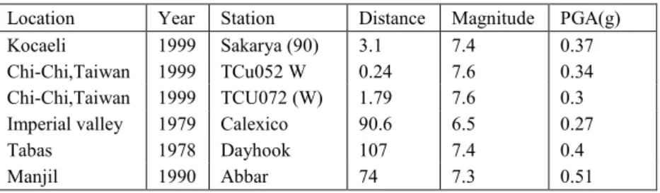
Based on buildings’ designing regulation (Iran 2800 standard [8]) building a construction on or next to active faults that have the possibility of fraction in earth surface at the time of earthquake should be generally avoided. This regulation does not sate any particular obligations for buildings near field to fault sites. In current research 6 earthquake record including three near field records with distance from epicenter less than 10 km and three records of far field with distance from epicenter 70 to 110 km are selected and then using Perform 3D software; selected models’ behavior is investigated under the effect of these 6 records of earthquake. The characteristics if mentioned records are shown in Table II. All these accelerograms are equaled based on the maximum effective acceleration to basis acceleration of the plan to provide the possibility of comparing the results of frames’ analyses under the effect of these records and the combination of these results are possible. The characteristics of selected records related to far and near field are respectively mentioned in Table II.
Table II
Near and far field of faults earthquake mapping
Location Year Station Distance Magnitude PGA(g)
Kocaeli 1999 Sakarya (90) 3.1 7.4 0.37
Chi-Chi,Taiwan 1999 TCu052 W 0.24 7.6 0.34 Chi-Chi,Taiwan 1999 TCU072 (W) 1.79 7.6 0.3 Imperial valley 1979 Calexico 90.6 6.5 0.27
Tabas 1978 Dayhook 107 7.4 0.4
Manjil 1990 Abbar 74 7.3 0.51
After finishing modeling, using non-linear time history analysis, the behavior of mentioned models is investigated under the effect of applied records. In this method, analysis is done through summing up or moment to moment integration during the time using stable average velocity method. This case is also known as the trapezoid or Newmark method β=1/4. In this analytical method, time step of integration should be identified. The number of steps is equal to whole time divided by the time of each step unless analysis finishes before earthquake ending. In non-linear time history dynamic analysis for modeling non-linear behavior of structures, three linear non-linear joints have been used. The characteristics of these joints are based on ‘seismic rehabilitation of existing buildings instructions’. As following, the obtained results from non-linear time history dynamic analysis will be proposed.
3. Results
3.1. Relative lateral displacement
According to calculations, the maximum value of stories permitted relative displacement for 8 and 12 story buildings is equal to 0.00476 as following as an
example, obtained results for stories relative lateral displacement of 12 story model obtained from time history non-linear analyses under the effect of various earthquakes have been shown in Fig. 8 and Fig. 9.
Kocaeli Imperial valley
Chi Chi 052w Tabas
Chi Chi 072w Manjil
Fig. 8. Relative lateral displacement of 12 story model with chevron bracing
Kocaeli Imperial valley
Chi Chi 052w Tabas
Chi Chi 072w Manjil
Fig. 9. Relative lateral displacement of 12 story model with cross bracing
As it can be seen in Fig. 8 and Fig. 9, under the effect of both categories of near and far field records, after installing linear and non-linear viscose dampers, the values of models’ relative displacement significantly reduce. Considering the type of record and type of bracing, this value of reduction covers the dichotomy of 30 to 70 percent. As it can be seen under the effect of near field records, linear and non-linear viscose dampers have relatively similar performances and reduce the rate of models lateral displacement in the same extent. Under the effect of far field records also this behavior can be seen. It was observed that most of reduction percentage in relative lateral displacement values after installing damper happens in chichi052 records (near field) and Imperial Valley (far field).
3.2. The response of obtained displacement of time history analysis
As following, the graphs of models’ time history responses are proposed in modes of without damper, with linear viscose damper and with non-linear viscose damper. As it can be observed in Fig. 10 - Fig. 13 non-linear viscose dampers have better performance in attracting and wasting energy of pulse strikes of near field records. As it is clear in these graphs, in most of modes linear and non-linear viscose dampers at the time of applying earthquake records acts in same phase with mentioned model and wastes entered energy till finishing the time of earthquake. It is also observed that in models with cross bracing, responses are close to each other in two modes of linear and non-linear viscose damper. It can be generally observed that during a stable designing process, cross bracing frames showed better performance.
Fig. 10. The response of 12 story model with cross bracing (near field)
Fig. 11. The response of 12 story model with chevron bracing (near field)
Fig. 12. The response of 12 story model with chevron bracing (far field)
Fig. 13. The response of 12 story model with cross bracing (far field)
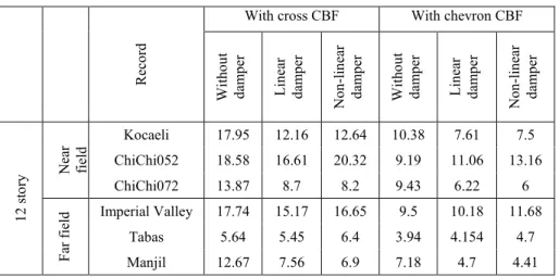
In Table III and Table IV the values of models base shear under the effect of near and far field records can be seen in modes of without damper, with linear viscose damper and with non-linear viscos damper. As it can be observed in these tables, the values of base shear under the effect of near field records are generally more that similar
values under the effect of far field records. Among two study categories also, created base shear in models with convergent cross bracings is more than mode that is used for models with divergent bracings. Noticing these tables, the effect of linear and non-linear viscose dampers can be well seen on obtained shear values.
Table III
Shear based amounts on a 12-storey models
Record
With cross CBF With chevron CBF
Without damper Linear damper Non-linear damper Without damper Linear damper Non-linear damper
12 story Near field
Kocaeli 17.95 12.16 12.64 10.38 7.61 7.5 ChiChi052 18.58 16.61 20.32 9.19 11.06 13.16
ChiChi072 13.87 8.7 8.2 9.43 6.22 6
Far field Imperial Valley 17.74 15.17 16.65 9.5 10.18 11.68
Tabas 5.64 5.45 6.4 3.94 4.154 4.7
Manjil 12.67 7.56 6.9 7.18 4.7 4.41
Table IV
Shear based amounts on a 8-storey models
Record
With cross CBF With chevron CBF
Without damper Linear damper Non-linear damper Without damper Linear damper Non-linear damper
8 story Near field Kocaeli 5.76 4.27 3.7 5.8 4.1 3.8
ChiChi052 10.6 8.36 7.28 18.95 8 7.52
ChiChi072 4.7 3.46 3.62 4.8 3.9 4.06
Far field Imperial Valley 10.76 7.3 5.87 35.56 7.45 6.2
Tabas 3.77 2.9 1.84 4.2 3.26 2.13
Manjil 3.44 2.8 2.74 3.57 2.85 3
As it can be seen in most of cases (except under the effect of near field records ChiChi052) after installing damper in models, under the effect of both categories, the value of shear has been reduced. It has also been observed that under the effect of near field records in most cases the rate of reduction in shear values in mode of using linear
damper is more than values such as using non-linear dampers. In another word the performance of linear viscose dampers in reducing the values of shear values is better than non-linear ones. It was also seen that in some cases, non-linear viscose dampers increase the values of base shear. For better comparison of results, Fig. 14 where shear values related to 8 and 12 story models can be used. As it can be seen in 12 story model with cross bracing, created shear values are more than models with chevron bracings. In 8 story models, this case has been vice versa.
Fig. 14. Comparing shear base in study models in without damper, with linear viscose damper and with non-linear viscose damper modes
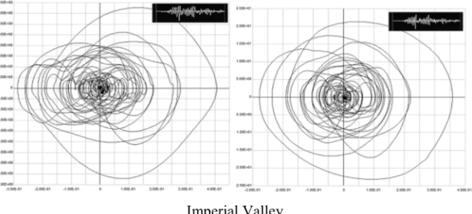
3.3. Dampers’ force-displacement curve
As following, an example for number of force-displacement graphs in 12 story models where their first floor has linear and non-linear viscose dampers installed, are shown under the effect of near and far field records. As it can be show in Fig. 15 - Fig. 18 Force-displacement curve for linear and non-linear dampers in 12 story model with cross and chevron bracing for near and far field.
Chi Chi 052w
Fig. 15. Force-displacement curve for linear and non-linear dampers in 12 story model with chevron bracing (near field)
Chi Chi 052w
Fig. 16. Force-displacement curve for linear and non-linear dampers in 12 story model with cross bracing (near field)
Imperial Valley
Fig. 17. Force-displacement curve for linear and non-linear dampers in 12 story model with chevron bracing (far field)
Imperial Valley
Fig. 18. Force-displacement curve for linear and non-linear dampers in 12 story model with cross bracing (far field)
The area of curves represents the work developed by damper during earthquake. In these graphs, horizontal axis represents damper displacement and vertical axis represents the values of force in dampers.
As it can be seen under the near field records, linear viscos damper has more displacement range compared to non-linear viscose dampers while the range of force displacement in non-linear viscose dampers is more. In another word, under the effect of near field records non-linear viscose dampers in less displacement range attract more energy and work more. It was also observed that force and displacement range in frames with cross bracings is widely more that frames with chevron bracings that the reason of this can be formability of each kind of used bracings in these frames. In another word, whatever lateral hardness is less, performed work by dampers will be more.
4. Conclusion
Frames with designed dual systems according to construction designing regulations against earthquake (Iran 2800 standard) showed ideal performance under the effect of applied records and their relative lateral displacement is in recommended area by regulation.
Obtained results in each case completely depend on designed frames and applied records but in spite of this it can be seen that structure shows different behavior under the effect of various records.
Before installing damper in mentioned models, relative lateral displacement values in cross bracing frame is less than similar values in chevron bracings while after installing damper, the response of both frames were very close to each other.
With installing viscose dampers in frames, relative displacement in each one of models reduces 30 to 70 percent. It was also seen than non-linear viscose dampers with α=0.5 reduces more relative lateral displacement values compared to linear viscose dampers.
Based on displacement time history graphs, during a designing stable process, frames with chevron bracings show better performance in reducing lateral displacement of frames and response in these frames will reduce in more extent after installing damper.
Under the effect of near field records, more values of base shear will be produced and this value is more in using cross bracings than frames with chevron convergent bracings.
Performed work by damper in frames with cross bracings is more than similar values in frames having chevron bracings.
References
[1] Norin F. V., Aurel S., Dan D. Behavior of concentrically braced frames with friction dampers, Pollack Periodica, Vol. 6, No. 1, 2011, pp. 59‒71.
[2] Adriana L., Aurel S., Dan D. Numerical simulation of bolted links removal in eccentrically braced frames, Pollack Periodica, Vol. 8, No. 1, 2013, pp. 15‒26.
[3] Miyamoto H. K., Gilani A. Design of a new steel-framed building using ASCE 7 damper provisions, Proceeding of ASCE Structures Congress, Vancouver, British Columbia, Canada, April 24-26, 2008, pp. 1-10.
[4] Tylor Devices, 2009, www.tylordevices.com, (last visited 6 January 2019).
[5] Powell G. Nonlinear analysis and performance assessment for 3D structures, Computer and Structure Inc,. PERFORM-3D, ver 5, 2007.
[6] Constantinou M. C., Symans M. D. Experimental and analytical investigation of seismic response of structures with supplemental fluid viscous dampers, Technical Report No.
NCEER-92-0032, National Center for Earthquake Engineering Research, Buffalo, New York, 1992.
[7] Makris N., Constantinou M. C. Spring-viscous damper systems for combined seismic and vibration isolation, Earthquake Engineering Structural Dynamics, Vol. 21, No. 8, 1992, pp. 649‒664.
[8] Standard No. 2800-84, Iranian code of practice for seismic resistant design of buildings.
3rd Edition, Tehran, Iran, 2007.
[9] Ashrafi H. R., Rad M. S., Far Y. A., Beiranvand P., Dadgar S. Investigating the effect of viscous damper on seismic behavior of steel dual frames with divergent bracing affected by near and far fields earthquake to fault, Civil Engineering Journal, Vol. 3, No. 7, 2017, pp. 526‒536.
[10] FEMA 356, Prestandard and commentary for the seismic rehabilitation of buildings, American Society of Civil Engineering for Federal Emergency Management Agency, Washington DC, 2000.