Double Layer Tensegrity Grids
Tatiana Olejnikova
Department of Applied Mathematics, Civil Engineering Faculty Technical University of Košice
Vysokoškolská 4, 042 00 Košice, Slovakia e-mail: tatiana.olejnikova@tuke.sk
Abstract: This paper describes the geometry of a double layer tensegrity grids assembled of three or four strut prismatic cells. The elementary cells are self-equilibrated and so is their assembly. The paper shows the creation of a planar grids composed of elementary equilibrium and grids with single or double curvatures composed of modified equlibrium shapes.
Keywords: tensegrity system; compression; tension; equilibrium; prismatic cell; grid structures
1 Introduction
A tensegrity structure is a class of tension structures consisting of tensile members and compressive members. In civil engineering, the light-weight characteristic of tensegrity is recognized as a significant advantage for space structures over conventional structural systems. According to the definition given by Fuller (1975), a tensegrity structure is a jointed structure consisting of continuous tensile members (cables) and discontinuous compressive members (struts).
A tensegrity system is established when a set of discontinuous compression components interacts with a set of continuous tensile components to define a stable volume in space. However, it needs to be slightly modified, taking into account the following factors: the components in compression are included inside the set of components in tension, and the stability of the system is self-equilibrium stability.
There are three types of tensegrity systems: tensegrity grids, tensegrity frameworks and tensegrity domes. This article describes the geometric relations of tensegrity grids assembled of prismatic cells. There are three orbits of members:
horizontal cables, vertical cables and struts. Each node is connected by two horizontal cables lying in a horizontal plane, one vertical cable and one strut. The
vertical cables and struts connect nodes in different horizontal planes. The members in each orbit are of equal length. The necessarily even number of nodes characterises the case of tensegrity systems. If “n” is this number, and if attention is paid to the spatial case, the minimal value of n is 6.
2 Geometry of the Prismatic Three-Strut Tensegrity Grids
The geometry of a spatial reticulate system is completely defined by its relational structure and by the knowledge of the coordinates x(k), y(k), z(k), k = 1,…,n, for its “n” nodes in reference to a chosen axis system. It is necessary for all internal elements (struts) to have the same length “s” and for the external elements (cables) to have the same length “c”.
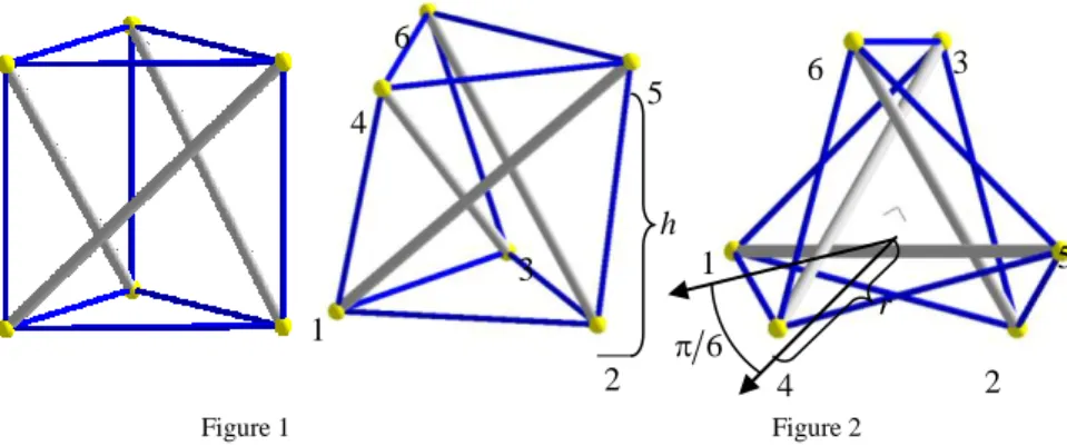
If the length of the struts is insufficient, the set of envelope elements will not have a definite shape (the system is then kinematically indeterminate). A first geometry is defined as a triangular prism (Fig. 1). This system is unstable, and another shape can be defined (Fig. 2) by relative rotation of the two triangles of cables in the parallel planes.
Figure 1 Triangular prism
Figure 2
Equilibrium, axonometric and top view
For a given value of the strut length, the totality of the cable net takes a singularly definite shape, which will be referred to as “null self-stress equilibrium geometry”. The geometric distance between the nodes corresponds strictly to the length of manufactured elements. Two geometrical ranges can be identified. If the relationship between the lengths of the struts and cables is ratio s c 21,467 and the relative rotation between triangles is 6. When the parameter r is specified, then the length of the struts is sr 32 3, the length of the all cables is cr 3 and the height of the equilibrium is hr 1 3.
6 1
1
2 3
3
2 4
4 5
5 6
6
r h
2.1 Bi-Dimensional Assemblies
This section describes examples of bi-dimensional assemblies. Several junction modes can be used: node on node, node on cable, cable on cable.
In type a) in Figure 3, the junction is operated with a single vertical (bracing) cable: each of two ends of the strut lies in different horizontal planes, and it will be used in a plane configuration leading to a double layer grid, in types b) and c), the junction is operated with horizontal cables.
a) b) c) Junction: node on vertical cable Junction: node on horizontal cable
Figure 3
Junction modes “node on cable”
A planar double layer tensegrity grid (Fig. 5) is created by using three-struts cells via a node on cable junction of type a) (Fig. 4).
Figure 4
Three cells junction in mode “node on vertical cable” of type a)
The node coordinates x
k,yk,z k of one cell in the planar grid are in (1):
, 1 33 4 2 - 12 k k 6 , 5 , 4 k for
0 3 ,
1 2 - 12 k k 1,2,3 k for
k , k sin k
, k cos k
1 1
1 0
0
r h h
h h z r
k y r
k x
(1)
where the parameter k0 1, r is a radius of a triangle created by the three horizontal cables in the cell, h is a height of the cell (Fig. 2).
Figure 5
Planar double layer tensegrity grid by three-struts cells
The node coordinates x1
i,j,k
,y1i,j,k
,z1i,j,k
of all cells in the planar grid displayed in Figure 5 are
i,j,k
k x
j, 1 i,j,k
k y
j, 1i,j,k
k1 x d y y d z z
x (2)
3) cos(j (i) 3) sin(j (i) (j) , 3) sin(j (i) - 3) cos(j (i)
(j) x y y x y
x
v v d v v
d (3)
where i1,...,6,j1,...,6,k1,...,6, coordinates x
k,yk,z k are expressed in (1), and
,
7 8 .2 7 3 2 , 6 11 4 , 6 9 , 3 5
, 3 5 , 2 4 , 2 4 2 , 3 9 4 , 3 5
, 2 , 2 , 0 1 1 4 , , 3 2 3
2 y
1 x
2 y
1 x
2 y
1 x 2 y
1 x
2 y
1 x
2 y 1 x y
x 2
1
v v
v v
v v
v v
v v
v v
v v
v v
v v
v v
v v v v v
r v r v
v
(4)
By maintaining the principle of elementary self-stressed cells, it is possible to modify the equilibrium shape so as to generate a double curvature system and spherical surface with a radius R. The elementary cell must be modified by the
parameter k0 in the equations (1) of the node coordinates of the upper triangles, for k4,5,6, i1,...,6,j1,...,6.
The transformation equations of the node coordinates of the lower layer of the planar grid to the spherical surface with a radius R and centre S(0,0,-R) for
1,2,3
k , i1,...,6,j1,...,6 and parameter k01 in equations (1) are:
R u
Rz
v u
R y
v u
R x
z y
x P z
y x
P
k j, i, sin k
j, i,
k j, i, sin k j, i, cos k
j, i,
k j, i, cos k j, i, cos k
j, i,
k j, i, , k j, i, , k j, i, k
j, i, , k j, i, , k j,
i, 1 1
1
(5)
where
i,j,k
k j, arccos i, k j, i, sgn k j, i,
, k j, i, k j, i, k
j, i, k , j, i, k 2
j, i,
1 1
2 1 2
1
d y x
v
y x
R d u d
(6)
coordinates x1
i,j,k
,y1i,j,k
are expressed in equations (2). The transformation equations of the node coordinates of the upper layer of the planar grid to the spherical surface with a radius R+h and a centre S(0,0,-R) for k4,5,6 and parameterR h k R
0 in equations (1) are
R h u
Rz
v u
h R y
v u
h R x
k j, i, sin ) ( k j, i,
k j, i, sin k j, i, cos ) ( k j, i,
k j, i, cos k j, i, cos ) ( k j, i,
(7)
where
i,j,k
k j, arccos i, k j, i, sgn k j, i,
k , j, i, k 2
j, i, , k j, i, k j, i, k
j, i,
1 1
2 1 2
1
d y x
v
h R u d
y x
d
(8)
Figure 6 shows the grid composed of three-strut cells transformed to the spherical surface. Figure 7 illustrates the transformation of the point P
k to the point
i,j,k
P , both located in the tangent plane of the spherical surface and its transformation to the point P
i,j,k
located on the spherical surface. Figure 8 displays a determination of the parameter d
i,j,k
and angles u
i,j,k
and
i,j,k
v , which are used in equations (8).
Figure 6
Double curvature tensegrity grid system
Figure 7
Transform.:P
k P
i,j,k
P
i,j,k
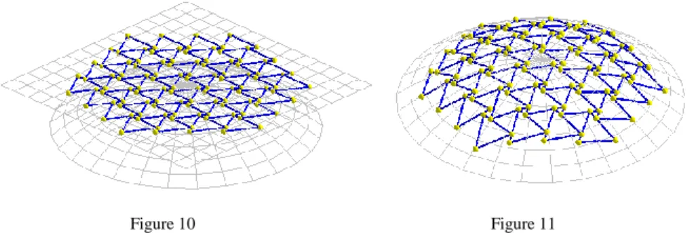
Determination of d(i,j,k),u(i,j,k),v(i,j,k)Figure 8 In Figure 9 are displayed the nodes and cables of the triangles of the bottom layer on the spherical surface. Figure 10 displays the triangles of the bottom layer of the tensegrity grid located on the tangent plane of the spherical surface, and in Figure 11 are these triangles placed on the spherical surface together with a spherical surface.Figure 9
Nodes and cables of the bottom layer of the spherical grid
i,j,k
P
i,j,k
P
kP x
S v(i,j,k) u(i,j,k) d(i,j,k)
0
y z
i,j,k
P
i,j,k
P
Figure 10
Triangles on the tangent plane
Figure 11 Triangles on the sphere
3 Geometry of the Prismatic Four-Strut Tensegrity Grids
Geometry of the four-strut cell is dependent upon only one parameter a (Fig. 11).
When the topology is defined, then the geometry is qualified by the whole set of coordinates, which is closely related to the self-stress equilibrium. When the parameter a is specified, then the length of the struts is sa 203 , the length of the cables of the bottom layer is c1a 2, length of the cables of the upper layer is c22a and the height of the equilibrium is ha 53.
Figure 11
Axonometric, top view and frontal view of the 4-strut cell
Planar double layer tensegrity grid is created by using of four-struts cells by node on node junction. The node coordinates P
k
x
k,yk,zk
for k1,2,3,4 and k5,6,7,8 of one cell in the planar grid are expressed in equations (9)7 7
8
h 1
2 1 2
3
3
4
4
5
5 6
6 8
a
k
k, k, k
cos
k , sin
k ,
k
2 2 k 1
2, 4 - k k and 8 , 7 , 6 , 5 k for
k , k sin 2 , k cos 2 k , k , k k
, 0 k 4, 1 2 - k k and 1,2,3,4 k
for
z a a
a a
z y x P
a z
z a a
a a
z y x P
z
(9)
where parameters a, h are illustrated in Figure 11. A planar double layer tensegrity grid is created by using 33 four-struts cells by node on node junction. The coordinates of the nodes in the planar grid for i1,...,3,j1,...,3,k1,...,8 are in equations (10)
i,j,k
k,, 1 j 2 k k j, i,
, 1 i 2 k k j, i,
z z
a y y
a x x
(10)
where x
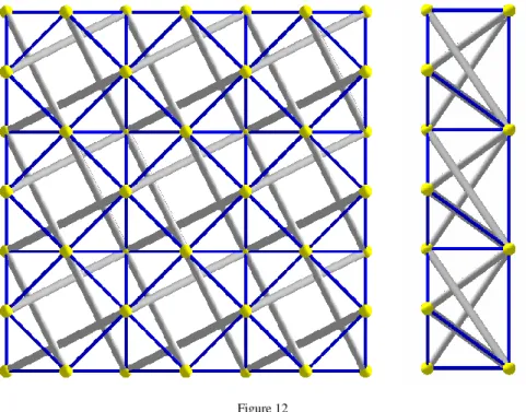
k,y k,z k are coordinates of the nodes of one cell expressed in (9).Figure 12 shows the planar double layer grid composed of 9 four-strut cells (top view and frontal view).
Figure 12
Top and frontal view of the planar double layer tensegrity grid of 33 cells
By maintaining the principle of elementary self-stressed cells it is possible to modify the equilibrium shape so as to generate a single curvature tensegrity grid system (on the cylindrical surface). Then the node coordinates are expressed in transformation equations (11), where the nodes located in the plane are transformated to the nodes located on the cylindrical surfaces with radii R and R+h, P
k P
i,j,k
, i1,...,7, j1,...,7
i,j,k
k sin
k
cos , ,1 j 2 k k j, i,
, sin k
cos k k j, i,
i i
i i
R R
z x
z
a y y
R z x
x
(11)
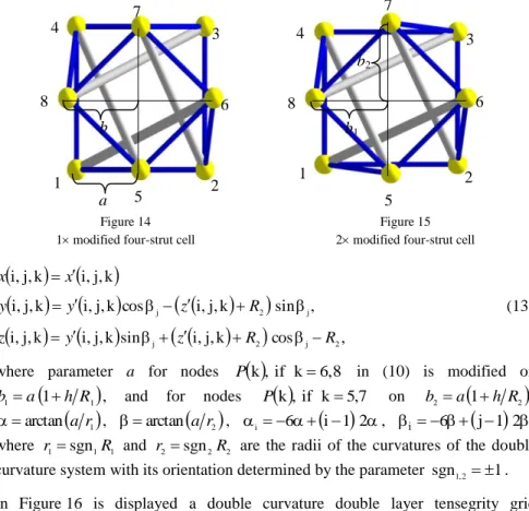
where parameter a for nodes P
k,for k6,8 in (10) is modified on
h R
a
b 1 illustrated in Figure 14, parameter i 6
i1 2, where
a R arctan
, R is radius of the curvature of the single curvature system.
Figure 13
Single curvature double layer tensegrity grid of 77 four-strut cells
In Figure 14 is displayed a 1 modified four-strut cell and in Figure 15 a 2 modified one. Figure 13 displays a single curvature double layer tensegrity grid containing 77 1 modified four-strut cells.
The node coordinates of the grid with double curvature (created surface with two curvatures R1 and R2) are
i,j,k
k sin
k
cos , ,k k j, i,
, sin k
cos k k j, i,
1 1
i
i 1 i
R R
z x
z
y y
R z x
x
(12)
Figure 14
1 modified four-strut cell
Figure 15 2 modified four-strut cell
i,j,k
i,j,k
sin
i,j,k
cos , , sin kj, i, cos
k j, i, k j, i,
k j, i, k j, i,
2 j 2 j
j 2 j
R R
z y
z
R z
y y
x x
(13)
where parameter a for nodes P
k,if k6,8 in (10) is modified on
1
1 a 1 h R
b , and for nodes P
k,if k5,7 on b2a
1h R2
,
1arctan a r
, arctan
a r2 , i 6
i1 2, i6
j1 2, where r1sgn1R1 and r2sgn2R2 are the radii of the curvatures of the double curvature system with its orientation determined by the parameter sgn1,21. In Figure 16 is displayed a double curvature double layer tensegrity grid containing 77 2 modified four-strut cells, where the radii of curvature are the same size and the same orientation r1r2. This grid has the form of a spherical surface.Figure 16
Double curvature double layer tensegrity grid 77, r1r2 a
b
1 2
4 3
5
6 7
8
1 2
4 3
5 8 6
b1 b2
7
In Figure 17 the tensegrity grid with the same radii but with opposite orientation
2
1 r
r has the form of the translational surface created by the translation of the circle with radius R1 along the circle with radius R2. In Figure 18 the tensegrity grid with different radii and opposite orientation r14r2 has the form of the translational surface created by the translation of the circle with radius R1 along the circle with radius R2.
Figure 17
Double curvature double layer tensegrity grid with radii r1r2
Figure 18
Double curvature double layer tensegrity grid with radii r14r2
Conclusions
This paper aimed to provide some examples of planar or non-planar prismatic tensegrity grid systems. Some are only geometrical studies without equilibrium considerations. It is not easy to define tensegrity systems. It could be claimed that everything in the universe is tensegrity with properties related to the continuum of tensioned components. Tensegrity structures are the most recent addition to the array of systems available to designers. The concept itself is about eighty years old and it came not from within the construction industry but from the world of arts. Although its basic building blocks are very simple – a compression element and a tension element – the manner in which they are assembled in a complete, stable system is by no means obvious.
The idea was adopted into architecture in 1960 when Maciej Gintowt and Maciej Krasiński, architects of Spodek, a venue in Katowice in Poland, designed it as one of the first major structures to employ the principle of tensegrity. The roof uses an inclined surface held in check by a system of cables holding up its circumference.
Another example of a practical implementation of the tensegrity system is Seoul Olympic Gymnastics Arena designed by David Geiger in 1980 for the 1988 Summer Olympics. The Georgia Dome, which was built for the 1996 Summer Olympics, is a large tensegrity structure of similar design to the aforementioned Gymnastics Hall.
Acknowledgement
This work was supported by the Slovak Grant Agency of Ministry of Education of the Slovak Republic within the project VEGA No. 1/0321/12 “Theoretical and experimental analysis of adaptive cable and tensegrity systems under static and dynamic stress considering the effect of wind and seismic”.
References
[1] Olejíková T.: Geometry of Tensegrity Systems, Proceedings of Scientific Works „Innovative Approach to Modeling of Intelligent Construction Components in Building 2010“, Košice, 2010, pp. 98-104
[2] Motro R.: Tensegrity. Structural Systems for the Future. Kogan Page Limited, London and Sterling, 2003
http://www.google.com/books?hl=sk&lr=&id=0n0K6-
zOB0sC&oi=fnd&pg=PR7&dq=Tensegrity:+Structural+Systems+for+the+
Future&ots=85AsVSIo_l&sig=amBKpKIADyZVPlpc0vVQ03g0OUI#v=o nepage&q&f=false
[3] Burkhardt R. W.: A Practical Guide to Tensegrity. Cambridge, USA, 2008, MA 02142-0021
http://www.angelfire.com/ma4/bob_wb/tenseg.pdf
[4] Kmeť S., Platko P., Mojdis M.: Design and Analysis of Tensegrity Systems, The International Journal “Transport & Logistics”, Vol. 18, 2010, pp. 42-49


