DOI: 10.1556/606.2018.13.2.8 Vol. 13, No. 2, pp. 77–86 (2018) www.akademiai.com
INVESTIGATION OF GLUED INSULATED RAIL JOINTS WITH SPECIAL FIBER-GLASS
REINFORCED SYNTHETIC FISHPLATES USING IN CONTINUOUSLY WELDED TRACKS
1 Attila NÉMETH, 2 Szabolcs FISCHER
1,2 Department of Transport Infrastructure, Széchenyi István University Győr, Egyetem tér 1 H-9026 Győr, Hungary, email: 1nemeth.attila@sze.hu, 2fischersz@sze.hu
Received 29 December 2017; accepted 9 March 2018
Abstract: In this paper the authors partially summarize the results of a research on glued insulated rail joints with fiber-glass reinforced plastic fishplates (brand: Apatech) related to own executed laboratory tests. The goal of the research is to investigate the application of this new type of glued insulated rail joint where the fishplates are manufactured at high pressure, regulated temperature, glass-fiber reinforced polymer composite plastic material. The usage of this kind of glued insulated rail joints is able to eliminate the electric fishplate circuit and early fatigue deflection and it can ensure the isolation of rails’ ends from each other by aspect of electric conductivity.
Keywords: Glued insulated rail joint, Fiber-glass reinforced fishplate, Polymer composite plastic material, Laboratory test
1. Introduction
The role of the rail connections (rail joints) is to ensure the continuity of rails without vertical and horizontal ‘step’, as well as directional break. The opportunities to connect rails are the fishplate joints, welding, and dilatation structure (rail expansion device) [1]. Rail connections are the weak points of the track, because their fishplates can compensate only the 60% of the moment of inertia of the rail. Wheel, during through-rolling (passing) the gap between the rail ends, hits the following (forthcoming) rail end, which is disadvantageous for the whole railway super- and substructure as well as the railway vehicle, too. Dynamic effects are much higher in case of vertical and/or horizontal step connections than in case of 0 ‘controlled’ one [2].
Requirements to rail connections are the followings [3]:
• to bear vertical and horizontal dynamic loadings at the discontinuity of rail;
• to avoid or limit (maximize) vertical and horizontal step between rail ends;
• to ensure longitudinal motion of rail ends due to dilatation force without structural damages;
• it should consist of few particles;
• its assembly and its components’ (parts’) exchange should be quick and easy;
• to fit to traffic control system;
• to fit railway safety rules.
The following types of normal fishplate joints in non-continuous welded track can be mentioned as it is shown in Fig. 1 (left picture) the common flat fishplate, in Fig. 1 (middle picture) the angled fishplate, and the bone shape fishplate (in Fig. 1 the right picture).
Fig. 1. Types of fishplates (common flat fishplate, angled fishplate, bone shape fishplate) (on the basis [3])
The types of fishplate joints can be differentiated in case of non-continuous welded track. The design can be solvable with stiff connection (joint), suspended joints and supported joints solutions.
Insulated joints are special types of fishplate joints, where the rail ends are insulated from each other, in this way metallic connection can arise neither at the rail ends, nor via fishplates. The types of insulated joints are the followings according to their evolution [3]:
• wooden fishplate, tie-framed (it is not applied nowadays);
• fiber-reinforced steel fishplate (it is not applied nowadays);
• pressed wooden fishplate;
• plastic fishplate (metamide, teramide);
• glued fishplate;
• P.C. Wagner type glued insulated joint, [1];
• GTI type glued insulated joint;
• plastic coated steel fishplate;
• polymer-composite (fiber-glass-reinforced plastic) glued insulated fishplate (Fig. 2).
Fig. 2. Apatech type fiber-glass-reinforced fishplates (Russian made [4]) (Photo: Authors)
Insulated joints can be applied in suspended and supported joints depending on their type in case of value of sleeper space and wheel load prescribed by manufacturer. High tensile strength bolts with great forces are used to press fishplates and rail together. In this way high friction force can be achieved, it causes that the high tensile forces cannot open the rail connection. Plastic profile lining (plate) is built between rail ends.
Insulated joints can be produced in plant as prefabricated elements with given length rails, as well as on the field, where they are assembled.
2. Research problems
During the research the authors have dealt with significant quantities of Hungarian, English and German literature (standards, technical regulations, technological instructions, brochures, scientific and non-scientific journals, research reports, laboratory protocols, etc.). In the international literature there are a lot of researchers who have been working with the topic of insulated rail joints, e.g. fatigue analysis, stress-strain analysis of fishplates, Finite Element (FE) modeling of Insulated Rail Joints (IRJs) and railway superstructures, [5]-[10], as well as the possible modification of railway track deterioration with special structure [11]-[14]. According to these literatures the authors of this paper formulated their research program, and the following sub-tasks have been dealt with [4], [15]:
• examination of rail systems;
• preliminary determination of the application conditions;
• determination of laboratory conditions and parameters;
• preparation of experimental specimens for laboratory testing;
• organizing professional experiences and knowledge on the preparation of laboratory tests.
According to railway maintenance experiences of Hungarian Railways (MÁV) and Raaberbahn, Győr-Sopron-Ebenfurth Railway (GYSEV), glued insulated steel fishplated joints need a lot of maintenance source (money and work) due to rail deformations (settlements). The next problem is the false (railway control) signal due to rail end failures (e.g. creasing, end post cracking, etc.), that results railway capacity restriction. Other problems are for example: glue material, end posts, rail ends, rail profile inner corner wear, plastic deformation etc.
3. Laboratory tests
In this chapter the authors introduce the results related only to laboratory tests.
Several laboratory tests were executed on different rail system Insulated Rail Joints (IRJs) [16], e.g. static shear tests of glue materials, static 3-point-bending tests before dynamic fatigue tests, 3-point dynamic bending fatigue tests with 3.5 million loading cycles, static 3-point-bending tests after dynamic fatigue tests, static 3-point-bending tests after dynamic bending tests until breakage, static axial pulling tests until breakage.
Static and dynamic bending and pulling tests were conducted on IRJs made with two different glue materials, as well as IRJs without glue material were also tested. Rail systems were three different types: MÁV48, 54E1 (UIC54) and 60E1 (UIC60) [4].
It should be noted: there is not any currently valid standard, technical specification (to the authors’ knowledge) for the polymer composite glued insulated rail joints, therefore CEN/CENELEC: WG18/DG11 standard [16] was used, which refer to the steel glued insulated railway joints laboratory tests.
Glue material shear tests
In the 1st shear test series of glue material were made 27 pieces glued specimen (c.a.
150-200 mm long rail, 300-400 mm long fishplates glued on both sides) and they were tested. It was executed with 8 different types of glue material (#5 and #7 have the same type glue), but 11 pieces specimen were not tested because of inadequate glue process and fishplates’ surface condition. In the 2nd test series 27 specimens were made (like the previous) again, all the 27 pieces specimen were tested, initial surface facing were also made. Based on the calculated shear strength values the #2 (B) and #4 (A) glue were chosen for further laboratory tests. The glue material #2 (B) is used at Österreichische Bundesbahnen (ÖBB, Austrian Railways), glue material #4 has very high shear strength. The shear tests of specimens were executed with ZD-40 type pulling machine, the samples were fixed on clamping frame. The measurement of displacement was measured with HBM W50 type LVDTs. Noted: standard deviation values were not used, the shear strength test of glue material is not prescribed in WG18/DG11 standard [4].
Static bending, fatigue (dynamic) and static bending breakage tests
The joint samples were made with three different rail profiles (MÁV48, 54E1 and 60E1), each with three specimens. The following tests were performed (specimens were fabricated by MÁV-THERMIT Ltd.) and the specification are the followings [4]:
• static bending test without breakage, Before Fatigue (BF), bays: 1490, 1200 and 1000 mm;
• fatigue test with 3.5 million loading cycles (bays: 1200 mm);
• static bending test without breakage, After Fatigue (AF), bays: as before;
• static bending test until breakage, bay: 1490 mm;
• number of specimens: 9 (length of specimens: 2×850 mm=1700 mm).
Using the standard [16] the values of bending moments were calculated separately rail systems depending on the maximal loading force and the supporting interval. The values of bending moments are shown in Table I.
Table I
Values of bending moments
Rail profile Bay [mm] Max. force [kN] Bending moment [kNm]
60E1
1490 114.44
42.63
1200 142.10
1000 170.52
54E1
1490 109.66
40.85
1200 136.17
1000 163.40
MÁV 48
1490 93.18
34.71
1200 115.70
1000 138.84
During the tests (before fatigue and after fatigue) the maximal vertical displacement in middle of the bay depending on the maximal force were measured and recorded. The layout of 54B1 specimen in case of 1490 mm bay static bending test before fatigue is shown in Fig. 3. After the test it was experienced that the vertical displacements were higher than in case of the regulation of steel glued insulated fishplate joint specimens [16], but the tested samples were passed the laboratory tests without any problems, so the fatigue tests were done without cracking’s, failures and breakages, there was not any visual failure on end posts, and the bending moments at breakage are much higher than the limit values.
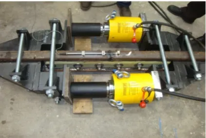
Static axial pull tests
The static axial pull measuring layout is shown in Fig. 4. Specimens were manufactured by MÁV-THERMIT Ltd. which length was 2500 mm (2×1250 mm), the screws quality was 8.8. The strength requirements were calculated according to WG18/DG11, at ∆T=50 °C, with ɤs=1.5 safety factor. The calculated minimal axial
pulling force separately rail systems are the followings [4]: 1450 kN for 60 rail profile specimen; 1319 kN for 54 rail profile specimen; 1168 kN for 48 rail profile specimen.
Fig. 3. 54B1 specimen - 1490 mm bay (static bending test) BF (before fatigue) (Photo: Authors)
Fig. 4. Conceptual layout of axial pull machine (Photo: Authors)
The additional safety factor of 1.15 was considered in case no breakage can be reached by pull machine (instrument). This higher pull force should be held for 2 minutes.
As an example the Table II shows the result of axial pull test in case of the 54 rail profile specimens. The majority of specimens could bear the prescribed pull force except the 60B11 and 54B11 specimens: there were sheared screws and breakage at low pull forces. Significant rail end displacements were recorded (3-12 mm) just before breakage point.
4. Future research
After the laboratory static bending, fatigue (dynamic) and static bending breakage tests the authors tried to calculate the (E×I) and (G×A) stiffness’s characteristics values of the tested specimens. Measured values were represented in graph, and linear regression for 0…90 kN load range has been taken into account (BF, AF, WG=without glue). Tangent values were calculated and registered and they were compared with the 90 kN loading force, so the vertical displacement (e) was received in the bay middle point of glued insulated rail joint specimens. The following formula was used for the calculating (the member of axial force is negligible):
A G
L F I E
L e F
⋅
⋅⋅
⋅
⋅⋅ +
= 48 4
3
, (1)
where e is the vertical displacement of glued insulated rail joint specimen [m], (deflection at bay middle point); F is the load (vertical force) [kN]; L is the bay (1.490 m, 1.200 m and 1.0 m); E is the Young modulus [kN/m2]; I is the inertia moment for x axis (horizontal axis) [m4]; G is the shear modulus [kN/m2]; A is the cross section area [m2].
Table II
Results of axial pull test - 54 rail profile specimens
Specimens
Calculated, prescribed axial
pull force (kN)
Measured maximal axial pull force (kN)
Displacement related to maximal axial pull force (mm) 54A11
1319
1548.73 3.272
54B11 1433.93 4.653
54A12 1605.287 3.725
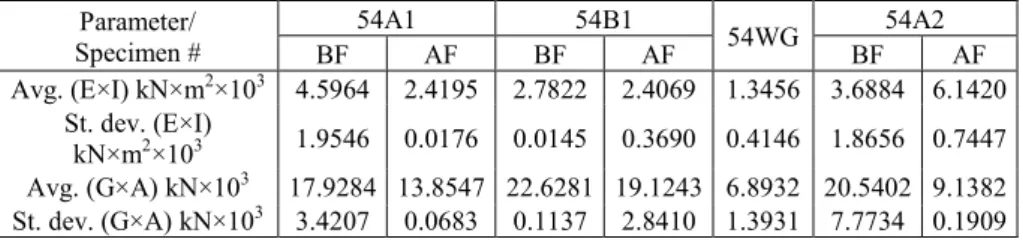
The calculated nominal bending stiffness (E×I) and nominal shear stiffness (G×A) values for 54 rail profile system specimens are shown in Table III.
Table III
Calculated approx. (E×I) and (G×A) stiffness’s related to 54 rail profile specimens Parameter/
Specimen #
54A1 54B1
54WG 54A2
BF AF BF AF BF AF
Avg. (E×I) kN×m2×103 4.5964 2.4195 2.7822 2.4069 1.3456 3.6884 6.1420 St. dev. (E×I)
kN×m2×103 1.9546 0.0176 0.0145 0.3690 0.4146 1.8656 0.7447 Avg. (G×A) kN×103 17.9284 13.8547 22.6281 19.1243 6.8932 20.5402 9.1382 St. dev. (G×A) kN×103 3.4207 0.0683 0.1137 2.8410 1.3931 7.7734 0.1909
The problem is that there relatively high deviation was between the values. In turn the values should be brought closer together.
In the future more laboratory tests and calculation are needed, because actually there is a pivot (knuckle) between the rails ends [17], so the above applied calculating formula is not accurate. Surroundings of the rail ends only the fishplates are working to a greater extent, which is shown in Fig. 5.
Fig. 5. (E×I) and (G×A) stiffness’s - supposition - there is a pivot (knuckle) between the rail ends
Additional bending and fatigue (dynamic) tests
The authors would like to execute measurements to additional 3 pieces of specimens, one piece for 48, one for 54 and one for 60 rail profile, which are the followings:
• static bending test before fatigue;
• 0.5 million cycle fatigue test;
• static bending test after fatigue;
• measurement after every 0.5 Mio. cycle;
• displacement measuring at 7 different points;
• 13 different bay values;
• breakage - specimens have not been broken after 3.5 Mio. cycles.
The goal is to evaluate the more precise deterioration process [14], [18] of fishplate joints.
Field tests
According to the prior field survey, rail joints for field tests were manufactured by
‘A’ type glue material. The polymer-composite joints and the assigned control joints (for comparison) were built-in the track in four different places, with three different rail
profiles, in three different speeds (Biatorbágy, Tatabánya, Győr, Lébény- Mosonszentmiklós railway stations) [4].
The authors’ future task is to investigate and make diagnostics of experimental (fibre-glass reinforced fishplate) and control (steel fishplate) rail joints (straightness tests, track geometry recording car measurements).
5. Conclusion
The ‘A’ and ‘B’ type glue materials were chosen with static shear tests.
The laboratory specimens were prepared using the selected two glue material types, and the initial laboratory static 3 point bending tests were executed (in three different rail profiles - MÁV48, 54E1, 60E1- , and in three different bays - 1490, 1200 and 1000 mm-, each with three specimens) the 3rd specimens for each rail profile were manufactured by ‘A’ type glue material. The specimens passed the laboratory tests without any problems, so fatigue tests were done without cracking’s, failures and breakages, there wasn’t any visual failure on end posts, and the bending moments at breakage are much higher than limit values.
The polymer composite rail joints and the control insulated rail joints were built-in the railway track at four locations (Biatorbágy, Tatabánya, Győr, Lébény- Mosonszentmiklós railway stations). The investigation and diagnostics of experimental (fiber-glass reinforced fishplate) and control (steel fishplate) rail joints (straightness tests, track geometry recording car measurements) are in progress.
After the laboratory and field tests the authors would like to model the results of the experimental joints in FEM simulation modeling software compared with the laboratory tests.
Acknowledgements
This paper is supported by EFOP-3.6.1-16-2016-00017 project.
References
[1] Szamos A. Structures and materials of railway superstructure, (in Hungarian), KÖZDOK, 1991.
[2] Kurhan M. B., Kurhan D. M. Features of perception of loading elements of the railway track at high speeds of the movement, Nauka ta Progres Transportu, Vol. 56, No. 2, 2016, pp. 136‒145.
[3] Gajári J. Railway construction I, (in Hungarian), Tankönyvkiadó, Budapest, 1983.
[4] Fischer Sz. Németh A. Investigation of polymer-composite fishplated glued insulated rail joints in laboratory, as well as in field tests for dynamic effects, Research Report (in Hungarian), Universitas-Győr Nonprofit Ltd. Győr, 2017.
[5] Mandal N. K., Dhanasekar M. Sub-modeling for the ratcheting failure of insulated rail joints, International Journal of Mechanical Sciences, Vol. 75, 2013, pp. 110–122.
[6] Mayers A. The effect of heavy haul train speed on insulated rail joint bar strains, Australian Journal of Structural Engineering, Vol. 18, No. 3, 2017, pp. 148–159.
[7] Rathod C., Wexler D., Chandra T., Li H. Microstructural characterization of railhead damage in insulated rail joints, Materials Science Forum, Vols. 706-709, 2012, pp. 2937–
2942.
[8] Shukri F. E., Lewis R. An experimental investigation and improvement of insulated rail joints, Tribology in Industry, Vol. 38, No. 1, 2016, pp. 121‒126.
[9] Zong N., Wexler D., Dhanasekar M. Structural and material characterization of insulated rail joints, Electronic Journal of Structural Engineering, Vol. 13, No. 1, 2013, pp. 75‒87.
[10] Zong N., Dhanasekar M. Sleeper embedded insulated rail joints for minimizing the number of modes of failure, Engineering Failure Analysis, Vol. 76, 2017, pp. 27–43.
[11] Major Z. Special problems of interaction between railway track and bridge, Pollack Periodica, Vol. 8, No. 2, 2013, pp. 97‒106.
[12] D’Angelo G., Thom N., Lo Presti D. Bitumen stabilized ballast: A potential solution for railway track-bed, Construction and Building Materials, Vol. 124, 2016, pp. 118‒126.
[13] Grygierek M., Kawalec J. Evaluation of pavement with geogrid stabilized unbound aggregate base within initial phase of trafficking, 3rd African Conference on Geosynthetics, Effective protection for natural resources, Marrakech, Marocco, 8-11 October 2017, pp. 864–871.
[14] Sol-Sanchez M., D’Angelo G. Review of the design and maintenance technologies used to decelerate the deterioration of ballasted railway tracks, Construction and Building Materials, Vol. 157, 2017, pp. 402‒415.
[15] Horvát F. Application of polymer-composite fishplates for glued insulated rail joints, (in Hungarian), Research Report, Széchenyi István Egyetem, Győr, 2012.
[16] CEN/CENELEC, WG18/DG11: Mechanical requirements for joints in running rails, Engineering Standard, 2010.
[17] Esveld C. Modern railway track, MRT Production, Zaltbommel, 2001.
[18] Nagy R. Description of rail track geometry deterioration process in Hungarian rail lines Pollack Periodica, Vol. 12, No. 3, 2017, pp. 141‒156.
![Fig. 1. Types of fishplates (common flat fishplate, angled fishplate, bone shape fishplate) (on the basis [3])](https://thumb-eu.123doks.com/thumbv2/9dokorg/1415681.119530/2.892.235.726.462.644/types-fishplates-common-fishplate-angled-fishplate-shape-fishplate.webp)
![Fig. 2. Apatech type fiber-glass-reinforced fishplates (Russian made [4]) (Photo: Authors)](https://thumb-eu.123doks.com/thumbv2/9dokorg/1415681.119530/3.892.246.584.244.499/apatech-fiber-glass-reinforced-fishplates-russian-photo-authors.webp)