Magyar Tudományos Akadémia
S z á m í t á s t e c h n i k a i é s A u t o m a t i z á l á s i K u t a t ó I n t é z e t e
C o m p uter and A u to m a tio n I n s t i t u t e , H ungarian A cadem y o f S c i e n c e s
PROCEEDINGS OF THE WINTER SCHOOL ON
C O N C E P T U A L M O D ELLIN G
VISEGRÄD
27-30 January, 1986.
Előd. KNUTH András MÁRKUS
(editors)
Tanulmányok 187/1986
Studies 187/1986
Felelős kiadó:
REVICZKY LÁSZLÓ
ISBN 963 311 216 8
ISSN 0324-2951
3
C O N T E N T S
LIST OF PARTICIPANTS Page
Tomiyama, T. : Integrated data description scheme ... ^ ' Knúth, E., Hannák, L . , Hernádi, A.: Foundations
of conceptual representations ... ^3
Brückler, H., Fritz, W . , Haase, V. , Kalcher, R. :
Intelligent databases ... ^5
Sikl&ssy, L.: Active collaborative systems ... g1 Hernádi, A.: Abstraction and data structuring ... 39 Davis, M . , Mitchell, R. : Semantic data models:
A software technologist3 s perspective ... 111
4
WINTER SCHOOL ON CONCEPTUAL MODELLING
Visegrád, 27-30 January, 1986
LIST OF PARTICIPANTS
A U S T R I A :
Brueckler, Helmut
Institut für Maschinelle Dokumentation Steyrergasse 25 a
A- 8010 Graz Geymayer, Barbara
Institut für Digitale Bildverarbeitung und Graphik Graz, Wastiangasse 6.
Haase, Volkmar H.
Institut für Maschinelle Dokumentation Steyrergasse 25 a
A- 8010 Graz Kalcher, Robert
Institut für Maschinelle Dokumentation Steyrergasse 25 a
A- 8010 Graz CZECHOSLOVAKIA:
Kelemen, Jozef
Department of Theoretical Cybernetics Faculty of Mathematics and Physics Comenius University
842 15 Bratislava
5
Tóth Attila INORGA
Moyzesova u l . 24.
Kassa, 04001
FRANCE:
Ganascia, Jean-Gabriel
Laboratoire de Recherche en Informatique Beit, 490, Université Paris-Sud
91405 Orsay Vrain, Christel
Laboratoire de Recherche en Informatique Bat. 490, Université Paris-Sud
91405 Orsay
HUNGARY:
CHINOIN Gyógyszer és Vegyészeti Termékek Gyára Rt.
Budapest, 1045. Tó u. 1-5.
Greguss Pál
Gödöllői Agrártudományi Egyetem Gödöllő, Pf.303., 2103.
Hernádi Ágnes
Központi Statisztikai Hivatal Számítóközpontja Budapest, 1023. Budai L.u. 1-3,
Farkas György Majtényi Edit Somogyi Péter
Magyar Tudományos Akadémia Automataelméleti TKCS.
Szeged, 6720. Somogyi Béla u.7.
Simon Endre
Toczki János
Magyar Tudományos Akadémia Központi Fizikai Kutató Intézet Budapest, 1525, Pf.49.
Krauth Péter Molnár Bálint Nicholson Dávid Papp Mikós
Magyar Tudományos Akadémia Számítástechnikai és Automati
zálási Kutató Intézet Budapest, Pf.63., 1502.
Bach Iván Bajza János Bernus Péter Éltető László Farkas Ernő Kelen Miklós Knuth Előd
Krammer Gergely Lakatos Péter Létray Zoltán Márkusz Zsuzsanna Máté Levente
Muzsik Gyula Naszódi Mátyás Réti Zoltán Ruttkay Zsófia Váncza József
Marx Károly Közgazdaságtudományi Egyetem Matematikai és Számitástudományi Intézet
Informatikai Osztály, Budapest, 1092. Kinizsi u.1-7.
Barna Gyula
Országos Tervhivatal Számitástechnikai Központja Budapest, 1149. Angol u.27.
Alcziebler Veronika Asztalos Domonkos Kiss Zoltán
Krekó Béla Ulbrich Péter
Országos Vezetőképző Központ
Budapest, 1087. Könyves Kálmán krt.48-52.
Breznay Péter Tamás
Kiss László Nándor
7
Számitástechnika Alkalmazási Vállalat Budapest, 1119. Szakasits Árpád ut 68.
Aszalós János Eiben Ágoston Kakas Károlyné Koch Péter
Kovács Kálmánná Laczay István Sebestyén Ferenc Szily Márta
Sztanev Ivánná
Völker-Müllner Ildikó
Számítástechnikai Koordinációs Intézet Budapest, 1015. Donáti u.35-45.
Balogh Kálmán Bedo Árpád Bogdánfy Géza Domán András Domokos Mária Farkas Zsuzsa Garami Péter
Harányi Annamária Losonczi Ilona Móri Judit Nagy Zsolt Sándor Gábor
Sántáné-Tóth Edit Solti Gabriella Sziray József ITALY:
Guarini, Nicola LABSEB
CNR - Padova
JAPAN:
Tomiyama, Tetsuo
Centre for Mathematics and Computer Science Interactive Systems
Kruislaan 413, 1098 SJ Amsterdam /NETHERLANDS/
NETHERLANDS:
Silóssy, Laurent
Vrije Universiteit Informatica Postbus 7161
NL- 1007 MC Amsterdam RNMANIA:
Barbuceanu, Mihai
Institute of Computer Technique and Informatics Bucharest
UNION OF SOVIET SOCIALIST REPUBLICS:
Salikov, Leonid
Moscow University Trishina, Elena
Laboratory for Computer Science
Siberian Division of the USSR Academy of Sciences Lavrent'eva av. 6.
Computing Centre
630090 Novosibirsk -
909
UNITED KINGDOM:
Davis, Megan
The Hatfield Polytechnic
School of Information Sciences POB 109, College Lane
Hatfield, Herts.
ALIO 9AB Seel, Nigel
STL
London Road Harlow, Essex CM17 9NA
UNITED STATES OF AMERICA:
Whinston, Andrew
Krannert Graduate School of Management Purdue University
West Lafayette
IN 47907
1 1
INTEGRATED DATA DESCRIPTION SCHEMA
- Issues on Representation o f Knowledge for CAD System s -
W inter School on Conceptual Modelling January 27-30, 1986, Visegrad
Tetsuo Tomiyama Interactive Systems
Centre for Mathematics and Computer Science Kruislaan 413, 1098 SJ Amsterdam, The Netherlands,
Telephone + 31-20-592 9333, Telex 12571 mactr nl.
A B S T R A C T
In this memo we discuss a knowledge representation schema fo r future C AD systems namely fo r mechanical design. First, we present an idea o f 11IC A D (Intelligent Integrated Interactive CAD) systems. These systems will be realized by using techniques o f knowledge engineering which are necessary to make the system intelligent and integrated. Among the elements o f a IIIC A D system, ID D S (Integrated Data Description Schema) is most important, because this is the mechanism to allow free and smooth information flow between system elements and because using IDD L, the language o f IDD S, we describe the design objects and the design knowledge fo r IIIC A D . In this memo, we try to derive the specifications fo r ID D S and ID D L from various discussions, such as formalization o f design process, representation o f machine, etc., in the context o f the conceptual modeling o f the design objects and their knowledge representation problem
12
1. INTRODUCTION
CAD systems are now not optional bu t necessary for m ost of industries. In this paper, we try to clarify many pro b lem s and troubles around conventional C A D systems. However, it is difficult to do so in general, because designing activities and philosophy for CAD systems are completely dependent on the ta rg e t area. Thus, those problems should be discussed in a particular field. We consider machine design as the subject area in this paper.
A typical p ro b lem of conventional C A D systems is, for example, that C A D systems do not check errors or m istakes of the designer. Usually, the final draw ings are so impressive that no one can detect those errors.
Another p roblem is integration of different models; this problem is especially significant in case of mechanical design which must deal with complicated structures. A design object must be viewed from many po in ts o f view, which m eans in the whole design process one object is represented in manv models, such as a geometric model, a kinematic m odel, a dynamic model, etc., each of which is allowed to h av e different attributes.
An idea of product modelling was proposed [KSH83] to integrate inform ation for all through CAD/CAM activities an d it seems very powerful. However, we have not yet seen a final solution which unifies all those models and guarantees the integrity and consistency of the inf''; ation. We may call such a m odel virtually metamodel and it is a great concern for researchers in this field.
In geometric m odeling, the problem of separation of the topology and the geometry of objects have been often discussed. Most of geom etric modeling systems have a feature for this separation, and quite often the dim ensions can be also separated. This issue would be generalized to the dis
tinction between stru ctu re and value. Sometimes, we want to separate the structure of an object from the values of attributes, because w hat we must first decide is the structure, for instance. On the contrary, quite o ften structural constraints influence values. In this case, separation of structure from value is not necessary. Therefore, we have two contradicting propositions which are causing a big problem in C A D fundam ental research:
• How can we get a language which distinguishes structure fro m value?
• On the other hand, how can we unify’ them fo r expressing the constraints?
In order to solve these problems of conventional C A D systems, we must avoid ad hoc approaches, because m ore or less designing is an intellectual process of human which may require a deep investigation. Therefore, we need a theory of CAD which would indispensably consist of the following three elem ents to make our direction of investigation firm.
(1) First of all, we need to know w hat are designing and design processes; i.e., we need a theory of design.
(2) We need som ething for expressing the design objects; i.e., we need a theory of design objects which, in our case, is translated into theory of machine.
(3) How to implciin-m ui u.aiiy a m atter of investigation recently in the field of knowledge engineering, pattem recognition, and computer graphics, for exam
ple. So, we need knowledge engineering as an im plementation technology. Moreover, because a futu re CAD system m ust be implemented as a tool for an intellectual process, we need theories of knowledge, action, learning, etc., that are more directly related to human thinking process; or, we need philosophy, cognitive science, psychology, etc., some
thing epistemological which may contribute to establishing a theory of design or a theory of machine. Traditionally in the database engineering field, this aspect has been also called conceptual modeling (BMS84).
In this paper, we first describe in Chapter 2 the direction of future CAD systems that are sup
posed to solve the problem s of conventional CAD systems. Secondly, we will point out require
m ents for future C A D systems coming from discussions on design theory.- philosophical considera
tion. and consideration about design objects, i.e., machinery in Chapter 3, 4. and 5. respectively.
T. Tomiyama Integrated Data IV-M-np<x.n SchMM
Among the elements of our future CAD system configuration, the meet: an tom to describe objects in an unified way is most important, because we need to realize ability u> describe -neumo- dels. for example. In this paper, we call this mechanism Integrated Data Description Schema (IDDS) and its language Integrated Data Description Language (IDDL). In those chapters »e gra
dually clarify the requirements for ID D S and IDD L In Chapter 6, those requirements result in IDDL specifications, and we will show an example of its highly experimental version. The language itself is still under development.
2. DIRECTION OF FUTURE CAD SYSTEMS
The direction of future CAD systems is deduced from problems of conventional CAD systems [ToY85a, ToY85b] The followings are the requirements for future CAD systems; the system should be
• intelligent;
• integrated;
• interactive.
Due to these requirements, our future CAD systems will be called IIICAD (pronounced as three-CAD) standing for Intelligent Integrated Interactive CAD systems. To realize a IIICAD sys
tem, knowledge engineering is regarded as one of the key technologies, because those requirements are deeply concerned with the nature of human intellectual activity such as designing. This means that future CAD systems will be realized to be knowledge based CAD systems and that they have considerably different configuration from the conventional ones.
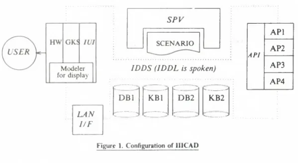
Figure I shows our configuration of a IIICAD system1. It has several important components.
(1) Supervisor (SPY): First of all there must be an intelligent supervisor which watches all the operations in the system, for example, user behavior, information flow, status of the sys
tem, etc. By doing this, it at least tries to understand the intension of the user. And, for instance, when the user made an obvious mistake, the supervisor should detect it by
LAN I /F
S P Y
SCENARIO
IDDS (IDDL is spoken)
___ -
DB1 K B l
r — - : --- --
rr~~ ; --- -—*
D B 2 K B 2
:: —_____■ .-s
API A P I A P2 AP3 A P4
Figur.e I. Configuration of IIICAD
! The author is no* preparing a material about the IIICAD system concepts.
January 27-30, 1986 Winter School on Conceptual Modelling
14
comparing the user's actions with a scenario which describes a standard designing pro
cedure. This would give intelligence to the system, although the supervisor itself does not have the initiative for the whole design process because the final responsibility for the design should be held by the designer.
(2) Integrated Data Description Schema (IDD S): Another important element is IDDS. One of them is to provide an integrated and unified method for describing models, i.e., a metamodel, in the system. IDDS is also a gateway for the databases and knowledge bases (DB/KB). Normally, the user does not have to pay attention to where and how to store and retrieve information. All the information, therefore, comes in and out through IDDS, which means databases and knowledge bases are transparent to the user. ID D S has a language called Integrated Data Description Language (IDDL), and the features of IDDS will be described as those of IDDL. S P V is drived in IDDL.
(3) Intelligent User Interface (IUI): The interface between the system and the user is con
trolled by several interfacing systems controlling from very low level input/output to very high abstracted level. The highest level interfacing system is called IU I which accepts messages from the supervisor or other application programs written in IDDL and sends them to lower level input/output systems like GKS which controls the hardware (HIV) or physical devices. It also accepts user’s inputs from, for instance, GKS and translates them to descriptions in IDDL which in turn will be sent to the supervisor.
(4) Application Program Interface (API): There must be an interface between IDD S and application programs. Following a scenario, SPV may invoke necessary and proper appli
cation programs for the situation. All the information which will be required by the application should be supplied by somebody; it can be the user, one of the databases, or another application programs. That information will be fed to the application program from ID D S in IDDL. and API should translate it from IDDL to proper data format.
(5) Scenario: A scenario is given beforehand to describe a chunk of procedures necessary' to complete the design task, including from abstracted descriptions to very low and simple ones. It may refer to other scenarios to perform a set of prodedures. According to the progress of the design, most suitable scenario will be selected by SPV dynamically. The whole set of scenarios selected during a design process may become a record of the design and may be used next time. A set of scenario is normally provided by the system designer and stored in the knowledge bases.
As you see, a 11IC A D system is controled in coorperation of SP V using scenarios and the user. Its basic actions are described as follows.
(1) Each system component, such as IU I, API, etc., reports its own status or requests to SPV.
(2) SPV asks KB whether there is a proper scenario for the situation created by the status reports from the subsystems.
(3) Having a proper scenario, SPV then passes requests from one subsystem to the most proper one. For example, data request from the application program might be passed to IUI, i.e., the user.
(4) The response will be returned to the subsytem which originally asked it. If the subsystem is satisfied with the provided data, it reports satisfaction to SP V and SP V will proceed according to the scenario. If not, S P V must take next procedure which might or might not be described in the scenario.
(5) If the scenario does not have description what to do next, SP V tries to find another scenario which looks valid in that situation. If it fails, SP V returns the system control to the user, reporting the system status, etc., and asks the user what to do.
Now. we have following two design policies for IDDL. These design policies (abbriviated DP) will be turned into the specifications later in Chapter 6.
T. Tomiyama Integrated Data Description Schema
January 27-30, 1986 Winter School on Conceptual Modelling
15
T. I (minania integrated Data Description Schema
DP 1: It must be possible that IDDL describe status information of the system.
DP 2: It must be possible that IDD L describe control information of the system, i*' origin and destination and the lime stamp.
As Figure l suggests, there exist a couple of layers or boundaries in the system. According to the kind of information flowing around, there is a boundary called semantics/syntax boundary between the supervisor and the rest which separates the semantics layer and the syntax layer. The meaning of these two layers or of this boundary will be described later in Chapter 4.
Another important boundary is the intension/extension boundary [T0Y86] which will be described more precisely also in Chapter 4. The extensional layer is a domain where all the infor
mation is described in relationships with other entities. Therefore, each entity may have no extra meaning other than being a symbol. On the other hand, in the intensional layer an entity is represented as a set of attributes; thus, an entity itself can be decomposable. This boundary exists between systems which care the information about entities themselves and systems which care the information about relationship among entities.
These two boundaries influences the implementation, because in a particular layer a particular tvpe of information is favored or required and because there exists a certain type of implementation techniques suitable for that particular layer. Thus, we have also several implementation layers in our IIICAD system.
As a result of having these layers, descriptions (or in conventional terminology, programs) for the supervisor only contain semantical and extensional notations, while descriptions for IUI and API are mainly occupied by transformation rules from semantical description to syntactical one and from extensional description to intensional one, respectively. This means there is a complete separa
tion between higher level description of the user’s intent and lower level description for the system control.
As we already pointed out, in order to build a II1CAD system, we need to introduce a tech
nique like knowledge engineering which has several important issues, such as knowledge representa
tion, knowledge acquisition, and inference, in appling it to real problems. When we consider a design problem, for example, we can find several knowledge representational problems; such as knowledge representation of machine, of design process, and design knowledge. Then, a very simple question may anse:
• Is it really possible to represent a machine in any computer language?
• I f possible, how do we do that?
This is a very philosophical question; in order to answer them, we need a theoretically sound basis to handle the knowledge. This means we need a design theory [ToY86],
3. ISSUES COMING FROM DESIGN THEORY
A good design theory is necessary from the following reasons.
(1) In order to build a CAD system that can support and help the designer in all the design pro
cess, we need to formalize a design process.
(2) In order to implement a IIICAD, we need knowledge engineering to handle our knowledge about design. This requires a theory to formalize our design knowledge.
General design theory proposed by Yoshikawa [T0Y86, Yos81] is a theory that can fulfill these two requirements. It is based on axiomatic set theory and assumes three axioms; and then we can derive theorems which are supposed to explain real design processes. From the result of general design theory, we can also deduce several important issues for the designing of a IIICAD system.
In this chapter we attempt to interpret important results of general design theory from a viewpoint of building a IIICAD system.
January 27-30, 1986 Winter School on Conceptual Modelling
16
T. Tomiyama Integrated Data Description Schema
3.1. Interpretation of Axioms of General Design Theory
Now, we try to show important issues coming from the axioms of general design theory.
These issues are not necessarily relevant to the theory itself but to the usage of the theory.
AXIOM 1: (Axiom of recognition) A n y entity can be recognized or described by attributes and/or other abstract concepts.
In general design theory, an entity itself is not defined; thus, it is a rather symbolic existence and anything can be an entity. Instead of defining directly what an entity is, we just guarantee the observability of entities, which made this axiom look rather trivial. However, in fact, it yields a further philosophically big issue, because it says that the representation of an entity is given by its attributes and that this is the only way for describing an entity (Figure 2). Actually, it says the description method of an entity concept must be extensional (or denotative), but not intensional (nor connotative). In other words, an entity is classified into some category according to its relative posi
tion to another entity, such that its relationships with other entities should be described. Here, classification is carried out by counting up of entities that belong to the same attribute concept, although it might be done in an either subjective or objective way.
Suppose we have a watch. This watch can be described as an integration of all the parts, from a metal case to a quartz oscillator. Then, it is possible to regard a list of those parts as the whole watch. But this is strange, because the list itself does not construct a watch. A watch is a watch because it is not a üst of parts. Therefore, extensional representation means something hohstic and all the attributes, including so-called structure, do not define the entity. Because attributes are gen
erated by observation followed by abstraction, they do have nothing to do with the real structure or whatever an entity has as its properties. Thus, we have:
DP 3: The expression of 1DDL should allow an extensional description.
Before proceeding to the next axiom, we define two terms, entity set and concept of entity.
DEFINITION 1: The entity set is a set which includes all entities in it as elements. By all entities, we mean entities which existed in the past, are existing presently, and will exist in the future. This set is denoted by S '.
DEFINITION 2: A concept o f entity is a concept which one has form ed according to actual experiences with an entity. This concept is different fr o m an abstract concept, t.e., a concept o f attribute or function, which is abstracted fro m the entity.
AXIOM 2: (Axiom of correspondence) The entity set S ' and the set o f entity concept (ideal) S have one-to-one correspondence.
January 27-30. 1986 Winter School on Conceptual Modelling
17
T. Tomivama Integrated Data Description Schema
This axiom indicates that it is enough only to think about the set of entity concept S instead of the entity set S', because between these two sets there is a perfect one-to-one mapoing. How
ever, by definition, S may include even entities which will exist in the future, and this ideal knowledge is far from our real knowledge. We have to consider the relationship between the logical world and the real physical world. In this context, this axiom guarantees the existence of a super
man who knows everything; in other words, it just shows an ideal and ultimate state of our knowledge, and that we have only imperfect design knowledge. This forces us to check the feasibil
ity or compatibility of the knowledge with the realities besides the completeness, soundness, and inconsistency checks in our realistic world.
DP 4: lDDL should provide facilities or a mechanism to check the completeness, soundness, and feasibility of the knowledge.
Now, we have the third axiom.
AXIOM 3: (Axiom of operation) The set o f abstract concept is a topology o f the set o f entity concept.
This axiom signifies that it is possible to operate abstract concepts logically, as if they were just ordinary mathematical sets. Accordingly, we get set operations, such as intersection, union, negation, etc. From a mathematical point of view, because axiomatic set theory is based on predi
cate logic which is normally associated with traditional two-valued logic or natural deduction, gen
eral design theory must also follow natural deduction. In natural deduction, a proposition P V -J>,
generated from any logical term, P, is always true by the law o f the excluded middle.
But, it is sometimes happens that we cannot decide between true and false in designing, unless we have another information or proposition Q to decide it. In fact, in everyday inference at least distinguishing known from unknown is necessary, which means introduction of intuitionism.
DP 5: It is necessary to introduce three valued logic (or intuitionism) to IDDL.
3.2. Useful Results of General Design Theory
Two important and useful results of general design theory [T0Y86] are described here. One is introduction of distance into the attribute space; the other is formalization of design processes with the metamodel concept.
3.2.1. Distance in the Attribute Space Two theorems tell the following:
THEOREM: In the real knowledge there exists a distance between two different entities.
THEOREM: In the real knowledge an attribute has a value.
When you read these two, you might feel that these two sound trivial. However, they have significant meanings and should be interpreted as follows:
(1) Given a certain metric, different entities, í i and s 2, can be measured differently; here, the metric will be given by a function
f:S->[0, 1], (S: Real knowledge),
and attributes have values, if we have a proper distance function, d, such that 0 < d(s\, s 2) = |/ ( i |) ~ / ( J 2 ) | < 1
(2) We may use attributes as the metric as far as attributes are second countable. That means all the attributes cannot be always measured. In order to clarify what kind of attributes can be measured, we probably need a study on representation methods of physical phenomena.
Only from this study, we will obtain a guide line about how to represent things rationally.
January 27-30, 1986 Winter School on Conceptual Modelling
l ü
T. Tomi) ama Integrated Data Description Schema
(3) When we have two candidate design solutions, A and B. it is possible to judge whether A is nearer to the specifications than B or not.
(4) It is also possible to measure the convergence speed of the design solution.
(5) There exists a mule between a horse and a donkey. However, it never guarantees the existence of a donkey nor gives how to creat a donkey, but it simply explains its existence.
In addition to these issues, the theorems indicate another important aspect about how to describe a value of an attribute. Usually, a triple of
[attribute name, type, value]
is used for describing an attribute and its value. However, this notation is vague because it is not clear whether this notation specifies the structure of an attribute or the value itself.
The theorem tells that there exists only a distance between two different entities and that the value of a particular attribute is generated from the function which gives this distance and a particu
lar standard entity which we can naturally set to 0. This means that the value, v, of an attribute, A, of a particular entity, e, is given by a function (or a predicate),
v = A(e).
We also distinguish two cases; one is when e has an attribute a, and we write this as A(e).
The other is when we want to say that A of e has value v. In this case, from now on we use a nota
tion.
v = A(e).
Note that the first notation suggests only that e has an attribute A of which value is e but not that e has a structure which is represented by A. As we discussed in Section 3.1, simply gathering attri
butes together does not constitute the structure.
DP 6: 1DDL should have a distinction between the fact that an entity has an attribute and the fact that an attribute has a value.
3.2.2. Formalization of Design Processes
Another important result of general design theory is that it can give good explanations of a design process together with a reasonable definition of metamodel. In fact, in general design theory we can derive a design process model called evolution model which indicates a design process is an evolution process of the metamodel [T0Y86].
A metamodel can be defined as a finite set of attributes and the metamodel set is defined as an intermediate space between the function space where specifications are written and the attribute space where solutions are obtained. A design process, in the evolution model, is explained as fol
lows.
Given the specifications functionally described, we may imagine a rough description of an entity concept as a candidate. The attributive description of this candidate will be detailed accord
ing to the progress of the designing. The whole design process will be explained as successive single steps. Each step corresponds to a single design procedure such as finite element analysis, motion analysis, data analysis of a specific experiment, etc. In this way the designing proceeds and accord
ingly the amount of information of the metamodel increases.
This evolution model suggests many important issues.
(1) A design process can be decomposed into small basic design procedures. The whole design process will be realized and simulated in a CAD system by a set of those basic procedures, which in turn means the whole process will be described by a scenario.
January 27-30, 1986 Winter School on Conceptual Modelling
19
Integrated Data Description Schema
(2) The metamodel ....xiuces models lot evaluation of functions [ToY85b], At each design step, the metamodel i.m um s attributive ...formation which has been decided so far. The design procedure for that step extracts s... mteresting attributes from the metamodel and creates a model for an evaluation. This poness w.ll be formulated as follows. Let M, be the metamo
del at a design step i and d be a pi.nedűre or function to extract information for the creation of a model m, under a specific c m umstance or field / ,. Here, functional evaluation of a design solution is equivalent to evaluate the model
in, I = d ( M , , f j ) .
Therefore,
would give the design decision, wl.e.e e is an evaluation function.
(3) By using the mcin.nodel concept, we can integrate all the models which appear in a designing process This means that in a design process the meiamodel is the central database from where we can get the necessary ...formation for creating models. And. as shown in the definition, a meiamodel should be described by a finite number of attributes expressed in a wav described in the previous so non
DP 7: I DDL should be used for des. nb.ng also for scenarios.
DP 8: IDDL should have an ability to describe metamodels, so that we get a model for an evaluation in a particular condition.
4. ISSUES COMINU I KOM PIIILONOPIHGM- (METAPHYSICAL) CONSIDERATION In this chapter we discuss issues about our philosophical view, because it is necessary to decide our standpoint f.n descnb.ng Hungs In whatever way the user may want to describe a thing, / DOS should provide a framework and a mechanism to complete it. In other words, IDDS must be flexible enough to make the user free to describe anything he wants.
We employ here Hist order preda ale logic for notation. Although IDDL does not necessarily
' ^ / h ' i n t p r u / p m e t 11c p i t f n r f A n v p n i p n p p
have to employ logic p n »gramming, in 11 ns chapter we just use it for convenience.
4.1. Syntax and Semantics
A IIICAD system should be inlrllty.ent by definition. Then, what is an intelligent workstation?
Because there is no consensus about intelligence, we can use our own definition2.
• An intelligent astern is one that ran handle user’s semantics.
• Semantics in a particular domain is what gives or defines (meaningful) relationships, names, etc. to the symbols used in thai domain.
• Syntax is defined to he equivalent to the topology on the set o f the symbols.
These definitions are more precisely denoted as follows. Let Sb and Op be the set of symbols and of operators, respc lively. The set of formulae F can be defined as the set of lists of symbols and operators; i.e.,
f = ((/, 12 • • ■ I, 1 .V/, V 4 6 Op, and grammatically valid}.
Relationships among symbols will be .Mined as predicate logic formulae as follows; this is the definition of syntax.
S, {<r,l)\r E R , I e f } ,
where R is the set of relationship Ol «ourse, R cannot be arbitrary; if we want to have first order
This also indicates il.ai -he .erm,nol..,Y n «■«' deftn),,on “ P°ssible
January 27-30, 1986 W inter S< luiol on Conceptual Modelling
20
T. Tomiyama Integrated Data Description Schema
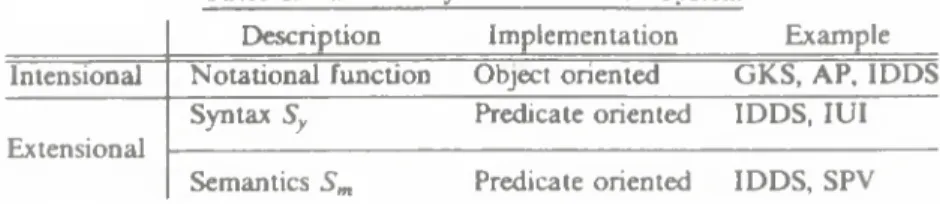
Table 1. Various Layers in a II1CAD System
Description Implementation Example
Intensional Notational function Object oriented GKS, AP, IDDS Extensional
Syntax Sy Predicate oriented IDDS, IUI
Semantics Sm Predicate oriented IDDS, SPV predicate logic, we need to restrict it such that
R C ] S b = 0.
Otherwise, we will have higher order predicate logic (see Section 4.4).
Then, semantics S m should be defined as a subset of syntax Sv by the user, i.e., C Sy,
so that it must have a specific meaning for the user under a specific circumstance. This is necessary, because a predicate cannot make sense unless the term (or subject) belongs to a particular category.
For instance, a fact,
weight(x, 50),
has no meaning, if x is not an object in the three dimensional world. If it is a point or a line, this fact is totally nonsense.
This distinction of syntax from semantics results in the following distinction of input checking, for instance. Suppose we have an input x, and there may exist three types of checking.
(1) x G Sb, x G Op, or x G F is a lexical check.
(2) x G Sy is a syntactical check.
(3) Xj, *2, ' ‘ ‘ e is a semantical check, because usually we must take the sequence of inputs into consideration.
This means that input checking and error recovery should not executed by one subsystem.
For example, lexical checks should be done by a lower level subsystem like GKS or IUI, whereas syntactical checks should be done by IUI, and semantical checks by SP V (see Table I).
DP 9: In IDDL, the semantics should be defined by the system designer; i.e., the system designer should be allowed to implement application dependent semantics.
4.2 Extension and Intension
As we have already pointed out in Chapter 2, there is a boundary called the in tension/extension boundary in a II 1C AD system. In Section 3.1, we have discussed that the world view of general design theory is extensional which at the same time means somehow holistic view.
Here, we think about this issue for further details, especially, from a viewpoint of CAD application.
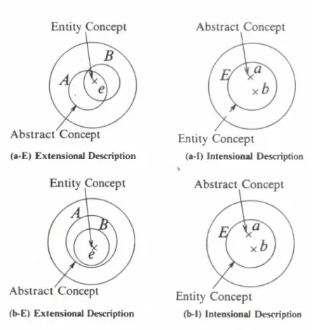
Figure 3 shows a comparison of the extensional description and the intensional one in a set nota
tion.
4.2.1. Extensional Description
An extensional description is defined as a situation where an entity concept is an element of the entity concept set and an attribute concept is its topology (see Figure 3 (a)). This description method has the following properties.
(1) Mathematically, the situation in Figure 3 (a) is defined as follows. Let e, and Aj be an entity concept and an attribute concept, respectively. Then, Aj is defined extensionally, January 27-30, 1986 Winter School on Conceptual Modelling
21
T. Tomiyama Integrated Data Description Schema
Abstract Concept Entity Concept
(a) Extensional Description (b) Intensional Description Figure 3. Extensional/lntensional Descriptions
using e,, as
* j = { e i , e 2, • • • }.
(2) As the definition above suggests, an attribute is a description found common to all those entities; this means first a common property is found by an observation and then this pro
perty is named an attribute, Aj. In other words, an attribute, Ajy is telling a relationship between entities, e iy e2,
(3) In this context, an attribute concept is a product of abstraction following observation and recognition of entities. Moreover, it is influenced by the sense of value which was dom
inant at the time of abstraction and also by the entire entity set. Therefore, an attribute concept is relative, but not absolute.
(4) On the other hand, an entity concept is philosophically a symbolic existence. It is nothing else but a symbol e,.
(5) An entity concept is only identified and described by attribute concepts defined to be a topology of the set of entity concepts. Thus, an entity concept is also relative (to other entity concepts), which means it will be only described in the relationship between that entity concept and others.
(6) An entity concept cannot be decomposed, because it is a symbolic existence and because it is not described by small parts. Therefore, the extensional description is holistic, which implies everything in the domain world will be denoted only by a collection of facts about relationships among (symbolic) entities. (From this, the description method can be called also fact oriented description.) Actually, in this metaphysics, existence of entities is not observed; there exist only relationships.
4.2.2. Intensional Description
On the contrary, an intensional description is defined to be a situation where an attribute con
cept is an element of the attribute concept set and an entity concept is its topology (see Figure 3 (b )). This description method has the following properties.
January 27-30, 1986 Winter School on Conceptual Modelling
22
T. Tonmama Integrated Data Description Schem a
(1) The situation in Figure 3 (b) is defined as follows. Let a, and Ej be an attribute concept and an entity concept, respectively. Then, using a,, Ej is defined intensionally by
Ej = { a], a 2, • • • }.
(2) The definition is based on a metaphysics that an entity should be described by its attri
butes. Sometimes, attributes may represent so-called structure of an entity, which may further suggest an entity is decomposable into small particles.
(3) An entity concept in the intensional description is generated from attributes which will be given somewhat existing beforehand and hence absolute. Therefore, an entity concept can be often described by a fixed number of attributes as a Cartesian product set, like
Ej = {(a,,a2, • • )| 2(a, ,a2, ■ ■ • )},
where 2 is an additional set of constraints.
(4) Philosophically, in an intensionally description, an entity concept is equivalent to a collec
tion of attributes, which will be regarded as an object. This is one of the properties of famous object oriented programming paradigm. In this paradigm, there exit no abstract u relationships among entities but concrete objects.
4.2.3. Further Notes on Extensional/Intensional Descriptions
The reader may have been confused by the terminology. The author admits that it is not so easy to understand the difference between an extensional description and an intensional description.
To solve this problem, let us consider a concrete example.
The implementational advantages and disadvantages of these two description methods will be further discussed in Section 4.2.4 and in Chapter 5, especially, when they are employed to CAD applications.
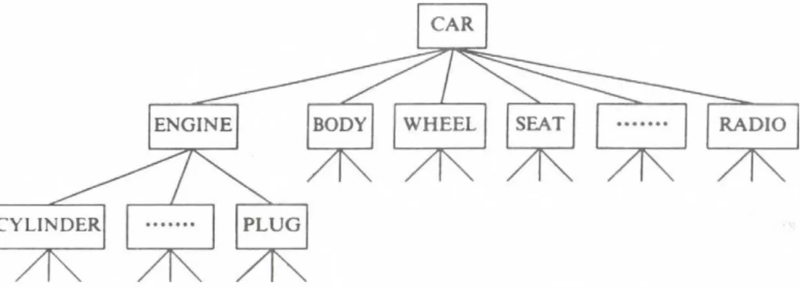
4.2.3.I. Hierarchical Example
Suppose you have a car which consists of lots of parts, from an engine to a radio, and the engine itself can be decomposed into thousands of small parts. We traditionally call these part- assembly relationships hierarchy shown in Figure 4 as a result of abstraction which is a typical human ability. Note that all the names appearing in this figure refer to concrete entities or instances; they are by no means generic names. Figure 4 is showing more or less something specific to your car.
Figure 4. An Abstraction of a Car (Some Part of Hierarchy)
Januarj 27-30, 1986 W inter School on Conceptual Modelling
23
T. Tomiyama Integrated Data Description Schema
In an extensional description method, probably the most natural interpretation of Figure 4 is as follows:
(1) First, we regard a symbol, such as CAR. as an atom which cannot be decomposed any more; thus, CAR is an identifier and can be replaced by another meaningless string such as @ AB 5306.
(2) Then, an arrow that connects two symbols is regarded as the relationship between them.
Maybe, we can use consistsof relationship for the moment, although its meaning cannot be directly defined right now.
(3) For example, the relationship between CAR and ENGINE will be interpreted such that CAR and ENGINE make a subset in the entity set as a topology;
consists o f = (CAR. ENGINE).
(4) Because the relationship consists o f here is specific to CAR and ENGINE, we need to introduce different names as many as the relationships. But, this is not necessary and we can use the same name for all other relationships, as far as we understand implicitly the meaning of these relationships are basically the same.
(5) Therefore, this hierarchy will be denoted in a following way, using a predicate consists of.
consists of(CAR. ENGINE), consists of(CAR, BODY), consists_of(CAR, WHEEL), consistsj)f(CAR, SEAT), consists_of(CAR, RADIO),
consists~of(ENGINE, CYLINDER), consists of(ENGINE, PLUG).
On the other hand, in an intensional description method. Figure 4 will be interpreted in a totally different way.
(1) In this description method, there is a strong belief that a CAR is decomposable into frag
mental parts such as ENGINE, BODY, etc. A CAR is built from combination of those parts.
(2) A symbol, such as CAR, is not a mere identifier, because it has an inner structure which is strongly related to a string “CAR.”
(3) Each part can be further decomposed, like ENGINE is decomposed into CYLINDER, PLUG, etc. Therefore, an intensional description method may lead us to ideas such as typing (or class, subclass, etc., any equivalent concept), object and its instance, etc.
(4) The relationship, consists_of, we have discussed is hiding in the structure of entities.
(5) The following is an intensional notation of this hierarchy.
CAR = (ENGINE, BODY, WHEEL, SEAT, • • • , RADIO) ENGINE = (CYLINDER, PLUG)
4.2.3.2. Meanings
It must be noted that concepts of syntax/semantics and extension/intension are very much alike but completely different (see T able I). It is possible that both of intensional and extensional descriptions have meanings.
• Intensional meaning is defined to be meaning o f a symbol.
• On the other hand, extensional meaning is defined as semantics which was defined in Sec
tion 4.!
January 27-30, 1986 Winter School on Conceptual Modelling
T. Tonmama Integrated Data Description Schema
The meaning o f a symbol is further explained in Section, 4.4, and it is in fact defined by the concept of object oriented programming paradigm.
4.2_3_3. Comparison of Extensional/Intensional Descriptions
It is interesting to compare the extensional description method with the intensional one. We can compare these two from various points of view.
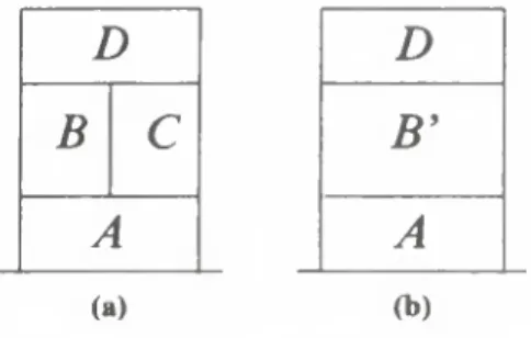
Figure 5 shows one of the disadvantages of the intensional description method. Figure 5 (a-E) shows that two different abstract concepts are denoting an entity. This situation can be also identi
cally described in the intensional description as in Figure 5 (a-I). However, as in Figure 5 (b-E), if two similar or hierarchical abstract concepts are denoting an entity, the similarity or the hierarchy cannot be expressed so well in the intensional description (see Figure 5 (b-I)); they are just represented in the same way as in Figure 5 (a-I).
The whole story tells that, in case of the intensional description method, slight differences in the meaning would be lost or ignored; or quite similar concepts would be recognized differently.
This type of loss of data would also happen in an exchange of information between an exten
sional description method and an intensional one. This can be pointed out mathematically Sup
pose jjc be an intension of x, and j\x be an extension of x. Mathematically, U-* = *
always holds; but, the other way around
(a-E) Extensional Description
Entity Concept
(a-I) Intensional Description
(b-E) Extensional Description (b-1) Intensional Description Figure 5. Comparison of Extensional/Intensional Descriptions
January 27-30, 1986 Winter School on Conceptual Modelling
25
T. Tomi) ama Integrated Data Description Schema
it* =*
does not always hold.
A famous example is the morning star and the evening star. The morning star has an exten
sion, Venus. The evemng star is an intension of Venus. Thus, an intension of an extension of an entity is not always identical to the entity. Therefore, when these two data description methods are necessary and when we need to exchange information between these two, we must be careful for loss or twist of information caused by the exchange.
4.2.4. Implementations! Notes on Extensional/Intensions! Descriptions
Although this chapter is for discussions from a philosophical or metaphysical point of view, it might be useful to compare implementations of extensions! and intensional description methods from a practical point of view. Let us examine it problem with a concrete example.
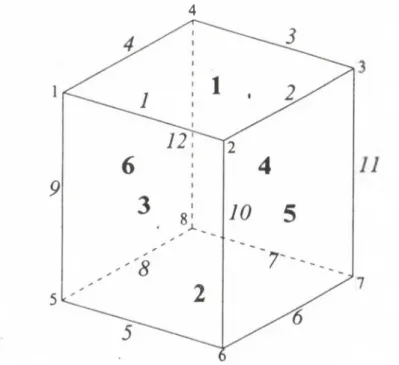
Figure 6 shows a cube, and the following facts denoted by predicates are its extensional representations, because in an extensional representation system the subject is an entity and the predicates are its attributes.
4
NB: Roman numbers indicate vertices. Italic numbers indicate edges. Bold numbers indicate sur
faces.
Figure 6. A Cube
January 27-30, 1986 Winter School on Conceptual Modelling
26
T. Tomiyama Integrated Data D escription Schema
vertex(1).
vertex( 8).
line{l).
line{12).
surface) 1).
surfaced), consists ofil, 9).
consists ofi5, 9).
consists ofil, 1).
consists ofi2, 1).
consists ofil, cube).
consists ofift, cube).
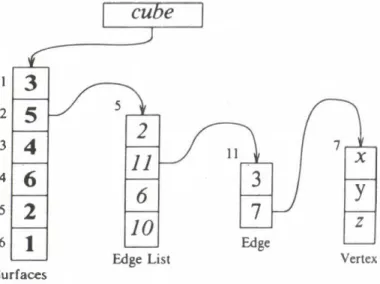
On the other hand, the intensional representation of this cube would be
«<*{(1.2, • • • , 6 ,7 , 2 , • •• ,72, 1,2, • • • ,8 )|2 (1 ,2 , • , 6, 7, 2, • • • ,72, 1,2, • • ■ , 8)}, where 2 implies the necessary conditions for this object to exist as a cube. Here, the entity, cube, is regarded as the predicate and its attributes are the subjects. Usually, this data structure can be real
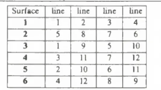
ized in CAD systems as a set of data connected by pointers illustrated in Figure 7, or sometimes as a tuple of a relational database [Lor82] ( Table 2).
In an extensional representation system, the data would be described by a set of facts (e.g., by predicate logic formulae) independent from each other. Even the constraints will be expressed gen
erally by a set of predicates. Generally speaking, to change or to add-new facts in this data representation scheme is not difficult. To modify a particular data is just a matter of checking the
1 2 3 4 5 6 Surfaces
Figure 7. Example of Data Structure of a Cube
January 27-30, 1986 Winter School on Conceptual Modelling
27
T. Tomiyama Integrated Data Description Schema
Table 2. Relation Type Data Structure of a Cube Surface line line fine line
1 1 2 3 4
2 5 8 7 6
3 1 9 5 10
4 3 11 7 12
5 2 10 6 11
6 4 12 8 9
data integrity using constraints, because all facts presented by predicates are independent.
Values of attributes are implemented as follows. For example, we regard a predicate, point(P),
as a function, and the value of this function becomes the coordinates, such as [X, Y, Z] = pomt(P).
This means we can treat an entity, its attributes (i.e. predicates), and their values individually.
On the contrary, in an intensional representation system, the data would be totally described in a chunk of data strongly and mutually connected by pointers together with the constraints 2 (see Figure 7). In this case, dependencies between the data become so strong that it is difficult to change or to modify the data schema. But, the meaning of a symbol can be easily decided by its relative position in the data structure.
Moreover, there is no separation of an entity, its attributes, and their values. For example, in a relational database system, we can separate relations and tuples like in Table 2. But, this separa
tion of the relation and the tuple can be so complete that there will be inevitable mutual dependen
cies such as the order among the data in the relation.
To sum up, an extensional representation system has the following implementational advan
tages.
EA1) It is easy to add new facts about entities, i.e., subjects.
EA2) It is also easy to modify facts and predicates.
EA3) Assertion of a proposition can be done by a simple search with pattern matching.
Disadvantages of an extensional representation system can be pointed out as follows.
EDI) It is rather difficult to grasp the entire meaning of what the logical formulae as a whole are saying, because we need to interpret logically all of the descriptions and because fairly large amount of computation would be required.
ED2) Predicates may loose their meanings; they only can have meanings defined by each other.
This is one of the typical disadvantages of formal logic and not particular to the exten
sional representation.
ED3) As far as implementation is concerned, it is not so easy to realize an efficient processing.
On the other hand, an intensional representation system has the following implementational advantages.
1A 1) Normally the meanings of each predicate can be easily understood, because the con
straints. 2, define them clearly.
January 27-30, 1986 Winter School on Conceptual Modelling
28
T. Tomiyama Integrated Data Description Schema
IA2) What a piece of data says can be easily understood from its position in the data structure, i.e., by its address.
1A3) As far as implementation is concerned, it is not so difficult to realize an efficient process
ing-
Disadvantages of an intensional representation system can be summarized as follows.
ID1) It is difficult to modify the data schema totally due to its strong mutual dependencies.
Adding new facts is easy.
ID2) Modification of the structure of propositions requires changing the constraints, 2. This is also difficult.
1D3) Assertion of a proposition may contain considerably complicated calculation of the con
straints, 2.
4.2.5. Summary
DP 10: IDDL should basically use an extensional data description method.
DP 11: From an implementational point of view, IDDL may be obliged to have also an inten- sional data description method because of performance, for example.
DP 12: When in I DDL both an extensional data description method and an intensional data description method are combined we need to carefully design it, because it is possible to have unexpected loss or twist of information in a data exchange between those two methods..
4.3. About Names
In this section, we would like to get rid of misunderstandings concerning names and attributes.
Generally speaking, names are considered to be attributes; or there is a saying that the simplest attribute is a name. However, this idea is doubtful.
Since IDDS is more or less a database system, it must have identifiers to distinguish entities (or entry records). An identifier, or any similar concept such as a key, are desired to be unique in one system [Lor82]; therefore, it should be created automatically by the system.
An entity concept must be identified in some way, although we cannot use attributes to iden
tify it because attributes will be created after entity concepts. Therefore, an entity concept will have an identifier which should be unique in the system and which is different from either a name or an attribute. However, a name system containing nouns in a natural language is normally used as an identifier, because under a certain circumstance nouns can be unique3.
On the other hand, an attribute can be regarded as a qualifier which describes properties of a thing. Sometimes, it happens that a concrete value of a name is filled with a qualifier which is not at all an identifier. For instance, you can call your dog like blacky because he is black. But, it is easy to find thousands of black dogs and, therefore, in this case his name blacky is less a name but more a qualifier. Nouns in a natural language is a monster, because they imply being qualifiers.
DP 13: Generally speaking, names are not attributes; nouns can be attributes, although they must be distinguished from identifiers.
DP 14: Names are categorized into two groups. System name is internal and should be unique.
User name is external and can be modified.
4.4. Predicates, Objects, and Functions
As we discussed heavily in Section 4.2, an extensional description method looks better than an intensional description method. We will later try to compare these two from a view point of
' Of course, this is not guaranteed for aJI the situations. People may have the same name!
January 27-30. 1986 Winter School on Conceptual Modelling
29
T. I(K im arna Integrated Data Description Schema
machine design or CAD application in the next chapter. To do so, in this section, we elaborate our idea along this distinction from a rather practical point of view.
An extensional description method is concentrated only in an aspect of relationships among entities, while an intensional one is focused on the structures of entities. Unfortunately, we cannot use exclusively either of them because of practical reasons discussed in the next chapter. Thus, we need to combine these two methods which look totally contradicting (see Design Policy 11).
As we have suggested in the previous discussions, an extensional description method is fact oriented which will be further transformed to predicate oriented, because it is heavily concentrated on the relationships of entities. On the other hand, an intensional description method is object oriented, since it forms closure.
Then, a question may arise:
• Is it possible to integrate these two (programming) paradigms?
A famous work to answer this question is conducted by 1COT, Japan, as an implementation of Concurrent Prolog [ShT83], Similar work is also carried out in University of Edinburgh [Bij86],
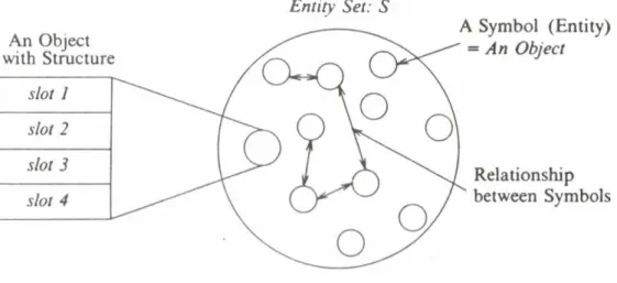
Figure 8 shows our paradigm combined the object oriented programming paradigm with the logic programming paradigm (in our terminology, predicate oriented), which will be discussed in Chapter 6 as the language IDDL.
Suppose small circles in this figure correspond to crosses in Figure 3 (a) which indicate enti
ties. and arrows to topology which indicates relationships between entities. An object may have internal memory spaces to store information just like slots in Minsky’s frame theory [Min75], but the internal structure of an object really does not matter because the user is interested not in how to store the information but in how to use it. We also introduce concepts such as message, class, inher
itance, etc., but in different terminology from the frame theory or from object oriented languages [GoR83]. For instance, note that here the message mechanism is realized only to get perfect infor
mation enclosure.
This paradigm is also similar to entity-relationship model in database theory [Che76], but there is a big difference that in our paradigm relationships can be created, modified, and deleted all the time during the execution. In conventional database systems once we fixed the data schema, it may never changed.
Entity Set: S
Januars 27-30. 1986 Winter School on Conceptual Modelling