Polymer 190 (2020) 122247
Available online 3 February 2020
0032-3861/© 2020 The Authors. Published by Elsevier Ltd. This is an open access article under the CC BY license (http://creativecommons.org/licenses/by/4.0/).
Self-feeding electrospinning method based on the Weissenberg effect
Haijun He
a, Min Gao
b, Daniel Torok
a, Kolos Molnar
a,c,*aDepartment of Polymer Engineering, Faculty of Mechanical Engineering, Budapest University of Technology and Economics, M}uegyetem rkp. 3-9, H-1111, Budapest, Hungary
bDepartment of Mechatronics, Optics and Engineering Informatics, Faculty of Mechanical Engineering, Budapest University of Technology and Economics, M}uegyetem rkp. 3-9, H-1111, Budapest, Hungary
cMTA–BME Research Group for Composite Science and Technology, M}uegyetem rkp. 3, H-1111, Budapest, Hungary
A R T I C L E I N F O Keywords:
Electrospinning Rod-climbing Meniscus parameters Nanofiber diameter Weissenberg effect
A B S T R A C T
In this study, we propose a novel electrospinning method, where a rotating rod is immersed into a polymer solution. Due to the Weissenberg effect of a non-Newtonian polymer, the solution can climb up to the tip of the rotating rod and form a meniscus for electrospinning. In order to investigate the effect of the shape of the meniscus on fiber diameter, we proposed four parameters to characterize the meniscus: the volume of the meniscus, the height difference, the half-angle of the Taylor-cone and the transition angle. Except for the height difference, the other three parameters have a positive influence on fiber diameter. We also calculated the climbing constant for different rod radii and different solution concentrations. The results show that the climbing constant can be an important parameter to influence fiber diameter.
1. Introduction
Electrospinning is a simple and convenient technique for the pro- duction of fibers with nanometer or sub-micron diameters. Because of the special properties of the fibers, i.e., large surface area, high porosity, and small size effect, etc., they can be applied in drug delivery [1], polymer composites [2] and many other fields. In conventional needle electrospinning operating with a polymer solution, a charged solution droplet is attached to a capillary tip by surface tension and viscoelastic stresses. The droplet is stretched into a cone with a certain apex angle (called Taylor-cone) with sufficiently large electrical forces. A jet emerges from the tip and then flies to a grounded collector [3]. During this, the solvent of the polymer jet evaporates and the jet is reduced into nanometer or submicron size range and solidifies. Finally, the nanofibers are deposited on the collector screen. The shape of the solution droplet on the needle tip has key importance in fiber formation and fiber morphology.
Back in 1882, Rayleigh [4] theoretically studied the stability of an isolated charged liquid droplet placed in an electric field and predicted that the liquid can be dispersed into fine jets when the electrical force is large enough to overcome surface tension, according to a stability cri- terion he constructed. Zeleny [5] adapted Rayleigh’s stability criterion
to investigate the instability of a charged sphere placed in an electric field, and based on experimental results he concluded that the disinte- gration of the droplet was due to instability caused by a high enough charge density. However, Taylor [6] pointed out the equilibrium equa- tion used in Zeleny’s case cannot be completely satisfied. Therefore, he corrected Zeleny’s methods and proposed the spheroidal approximation as the critical shape for two cases: (1) a charged droplet at a given po- tential, and (2) an uncharged droplet in a given uniform field. Taylor also concluded the tip half-angle of the cone (later called Taylor-cone) was 49.3�, which was the boundary between the stable charged droplet and the disintegration or jet emission from the cone vertex. In 2001, Yarin et al. [7] proposed a hyperboloidal approximation of the droplet shapes based on the experimental data acquired from electro- spinning, which was consistent with the prediction of the stable critical droplet shapes of inviscid, Newtonian, viscoelastic and purely elastic fluids. They also found that the Taylor-cone did not represent a unique critical shape, because for an elastic fluid, the sharpness of the critical hyperboloid was not only determined by the electrical force but also the elastic force and surface tension. In order to understand and predict the effects of parameters on the fiber diameter, Thompson et al. [8] evalu- ated the effect of individual parameters on the jet cross-section radius as a function of the distance from the nozzle. Thoppey et al. [9] produced
* Corresponding author. Department of Polymer Engineering, Faculty of Mechanical Engineering, Budapest University of Technology and Economics, Muegyetem } Rkp. 3-9, H-1111, Budapest, Hungary.
E-mail address: molnar@pt.bme.hu (K. Molnar).
Contents lists available at ScienceDirect
Polymer
journal homepage: http://www.elsevier.com/locate/polymer
https://doi.org/10.1016/j.polymer.2020.122247
Received 4 November 2019; Received in revised form 23 January 2020; Accepted 31 January 2020
high-quality fibers by adjusting the conductivity of the solution, which led to a narrow jet. The narrow jet enhanced surface charge density and facilitated the formation of thinner fibers. Although the analytical pre- diction of the critical electric field to stretch out a jet from a droplet was given by Hinguera [10]. In their study, there was no characteristic droplet size. It was reported that capillary length, a parameter frequently used in wetting theory, can determine the size of the meniscus [11,12]. More recently, in order to describe the transformation from droplet to jet and the initial position of the jet, Liu et al. [13]
defined three observable droplet shape parameters to describe the whole shape: L-R curvature, initial jet diameter, and transition slope which quantified the droplet part, the transformation from droplet to jet part and the jet part. They investigated the correlations between the shape parameters and fiber diameter.
In all of the above-mentioned papers, the droplet was investigated for needle electrospinning, as there are no stationary droplets in most needleless electrospinning processes. Generally, needleless electro- spinning produces nanofibers from moving spinnerets or from a free solution surface, where fluctuation and conical spiking can be intro- duced by a high electric field [14,15]. To maximize local electric field intensity, researchers developed several electrospinning methods involving a rod [16–23]. In most of these rod electrospinning tech- niques, traditional microextrusion with a pump, or the rotation of a spinneret, or different auxiliary fields (e.g. gravitational field, magnetic field) were used to supply the polymer solution continuously. Needle electrospinning is usually used to make nanofibers from a PEO solution with a viscosity ranging from 2.77 Pa.s to 13.05 Pa.s [24]. If the viscosity of the solution is more than 13.05 Pa.s, pumping the solution through the needle with a micrometer diameter is very difficult because of the high flow resistance, and it can also clog the needle. In the above-mentioned rod electrospinning methods, the suitable viscosity range for electrospinning should be even lower, because only lower viscosity means a high enough flowability to provide a sufficient solu- tion on the spinneret. And a solution with lower viscosity can form a thinner solution film on the spinneret, which requires a weaker elec- trical force to stretch the liquid film into jets.
To address the above-mentioned problems, we propose a novel method to pump the polymer solution using the Weissenberg effect. In this paper, we introduce a different needleless electrospinning method with a rod. We have called it rod-climbing electrospinning (RC-ES), where a relatively stationary and stable meniscus is formed during the electrospinning process. Therefore, we focused on the effect of meniscus shape on fiber diameter in the case of needleless electrospinning. Due to the Weissenberg effect in non-Newtonian liquids, the polymer solution can climb along the rotating rod by itself. The conical tip of the rod serves to support the formation of a stationary and stable meniscus. The intention of this paper is to demonstrate the viability of the method and to evaluate the correlation between the parameters of the meniscus and nanofiber diameter.
2. Experimental 2.1. Materials
Polyethylene oxide (PEO) solutions with different concentrations (6.0 wt%, 7.0 wt%, 7.5 wt% and 9.0 wt%) were prepared by dissolving PEO (Sigma-Aldrich, USA, molecular weight of 400,000 g/mol) in a water/ethanol mixture (3:1).
2.2. Rod-climbing electrospinning setup
The Weissenberg effect or rod-climbing is one of the remarkable flow behaviors of polymer melts and solutions, and it is well-known for many non-Newtonian fluids. A part of a vertical rod is immersed in a concentrated polymer melt or solution in an open cylindrical container.
The top part protrudes from the liquid, as shown in Fig. 1a. When the rod
is rotated, the melt or solution begins to climb to the upper part of the rod. The climb is associated with the nonlinearly distributed normal stresses [25]. During rotation, a basic laminar flow is formed. Besides the shear stresses due to the rotation, normal stresses begin to act in a radial direction as a consequence of the non-Newtonian behavior. These normal stresses tend to push the liquid up the rod. Fig. 1b schematically illustrates the setup of rod-climbing electrospinning (RC-ES) inspired by the Weissenberg effect. The setup includes a 3D printed container, a 3D printed rotating rod, a motor, a high voltage power supply and a grounded collector. We printed 3 rods from non-conductive photo- polymer resin, with the same length (45 mm) and different radii: 2.5 mm, 3.5 mm and 5 mm (see Fig. 1c). The upper end of each rod was designed to be conical with the same cone height of 5 mm, which is suitable for comparing the geometry of the conical droplet on the rod tip. It is also necessary to keep the rod in a precisely vertical position so that droplet geometry can be captured during the electrospinning pro- cess. The liquid container was filled with the polymer solution, and the rod protruded 40 mm into the solution. When the rod was rotating, the polymer solution was climbing up to the rod tip due to the Weissenberg effect. Then a high voltage was applied to charge the solution until the voltage reached a threshold value when a polymer jet was ejected from the tip of the liquid meniscus (see Fig. 1d). Finally, the fibers were deposited on the collecting plate continuously and nanofibers were collected on the collector, as shown in Fig. 1e.
The rotational speed of the rod was measured with a contactless digital laser tachometer (Xinsi tachometer, China). A small piece of reflective paper was attached to the motor drive shaft, and a light beam ejected from the Tachometer was aimed at the reflective paper while the driveshaft was rotating. This tachometer is capable of measuring rota- tional speed with a precision of �1 rpm.
2.3. Electrospinning parameters
In this study, we mainly investigated the effect of meniscus param- eters on nanofiber diameters when only a single jet formed on the meniscus surface. By default, the collecting distance was 25 cm. The rod rotation speed which generated a stable meniscus shape was controlled.
It is because if the rotation speed of the rod is too high, the solution rises high enough and then collapses due to the higher centrifugal force. This results in an unstable meniscus, which prevents the continuous fiber formation. But sometimes we observed multiple jets intermittently (see Fig. S1) in the case of high rotation speed. It is because higher rotation speed disturbed the meniscus, which triggered the electrospinning from different areas of the meniscus. Inversely, if the rotation is too slow, the solution does not climb high enough. We maintained a single jet while using voltages between 25 kV and 45 kV. The menisci of 15 samples were examined. The results were obtained with 3 different solution concentrations, 3 different voltages and 3 different rod radii. The con- ditions of the experiment are listed in Table 1. Relative humidity and ambient temperature during the experiments were 35 �2% and 25 �2
�C, respectively. It is worth emphasizing that even though the 9.0%
concentration PEO solution can not be used for making fibers with the single capillary electrospinning, we were able to get sub-micron fibers with the same PEO solution via self-feeding electrospinning method (see Fig. S2).
2.4. Climbing height measurement
In the rod-climbing experiments (without turning the power supply on), the phenomenon was filmed with a high-speed camera (Keyence VW-9000, USA) with a frame rate of 1000 fps and 5-s-long videos were captured. We obtained the climbing height of the solution on the rod surface by evaluating the captured frames with the ImageJ program. The known rod radius was used as a scaling factor.
2.5. Meniscus shape characterization
A digital camera (Nikon D600, Japan) was mounted in front of the apparatus on an adjustable tripod, and its position was fixed at the same level as the edge of the container for all the experiments. The shape of the meniscus was measured with the MATLAB program. The shape of the meniscus surface was obtained by edge detection and expressed in pixels. Using the known rod radius as the scaling factor, the surface of the meniscus was described with an expression in mm units. We used the discrete measured points to produce profiles of the free surface by fitting a continuous curve on the points.
2.6. Fiber morphology characterization
The morphology of the nanofibers was examined by scanning elec- tron microscopy (SEM; JEOL 6380 LA, Japan). Each sample was coated with a gold-palladium (Au/Pd) alloy beforehand. For each sample, we measured 100 random fibers and obtained the diameter frequency dis- tributions using the Image J software package.
3. Results and discussion
3.1. Solution supply with the Weissenberg effect 3.1.1. Rod-climbing behavior
Prior to the electrospinning experiments, we performed rod-climbing experiments with the PEO solution. Simple experiment setup for rod- climbing involved a beaker and a rotating rod. The diameter of the beaker was 100 mm. Fig. 2 shows that when a rotating rod with a radius of 2.5 mm was inserted into a PEO solution with a concentration of 7.5%, climbing height increased with the increase of rotation speed because of the normal stress difference during the rotation. When rotation speed was over 1000 rpm, the meniscus lost its stability and collapsed as shown in Fig. 2e and f. If rotation speed was further increased, the liquid ruptured and was thrown away from the rotating rod because of the high centrifugal force.
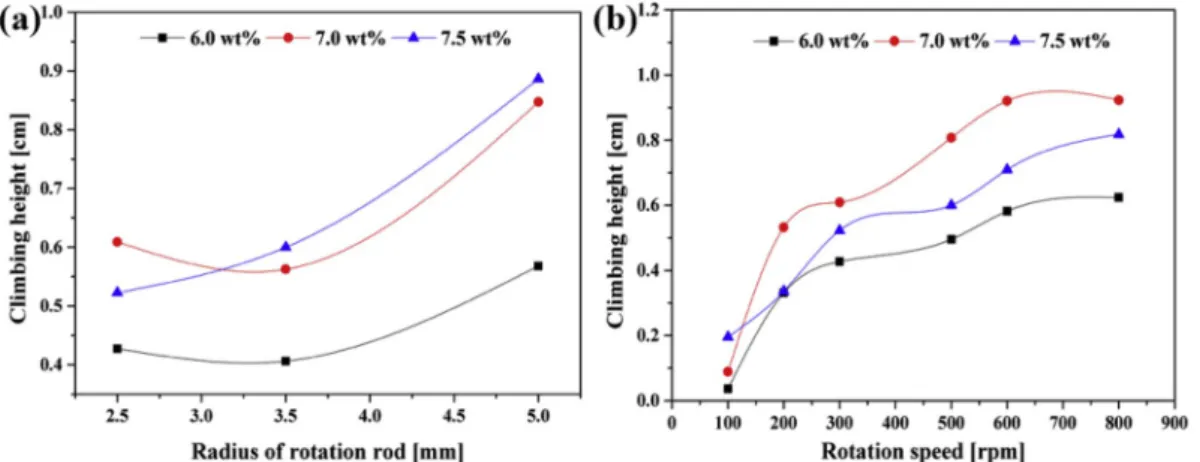
The Weissenberg effect was also tested with the different rods and various solution concentrations, and rotation speed increased from 100 to 800 rpm. As shown in Fig. 3a, climbing height (h) increases with the increase of rod radius at room temperature for all the samples. When the rotation speed of the rod is constant, a larger rod radius means greater shear force on the polymer solution, due to the larger linear velocity at the edge of the rod. It can provide more resistance to deformation and more pressure in the climbing direction. Therefore, the solution can climb higher along the rod. Fig. 3b illustrates that when rotation speed Fig. 1. (a) Schematics of Weissenberg effect, (b) schematic drawing of rod-climbing electrospinning (RC-ES), (c) rods used for electrospinning, (d) optical image of the meniscus in electrospinning, (e) SEM image of nanofibers produced by RC-ES.
Table 1
Processing parameters for electrospinning.
Sample
no. Concentration (wt
%) Voltage
(kV) Rod radius
(mm) Rotation speed (rpm)
ES-1 6.0 25 3.5 350
ES-2 6.0 35 3.5 350
ES-3 6.0 45 3.5 350
ES-4 7.0 25 2.5 240
ES-5 7.0 35 2.5 240
ES-6 7.0 45 2.5 240
ES-7 7.0 25 3.5 260
ES-8 7.0 35 3.5 260
ES-9 7.0 45 3.5 260
ES-10 7.0 25 5.0 150
ES-11 7.0 35 5.0 150
ES-12 7.0 45 5.0 150
ES-13 7.5 25 3.5 220
ES-14 7.5 35 3.5 220
ES-15 7.5 45 3.5 220
increases from 100 rpm to 800 rpm, climbing height also increases. It can also be explained with shearing forces. The shearing forces increased with the increase of rotation speed, and climbing height was greater.
The concentration of the solution also plays an important role in rod- climbing height (Fig. 3a and b); higher concentrations can provide more stress in the climbing direction [26]. Mei et al. [27] observed that the shape of a high concentration solution was slender as it climbed when the rod with a micro-scale diameter was used. As the concentration of the solution was increased, the viscosity of the solution also increased (Table S1), and a more concentrated solution generated larger resistance against shearing deformation than a dilute solution. However, the re- sults of experiments do not correspond with the Micro Weissenberg Ef- fect (MWE) concerning concentration. When rotation speed was constant, higher concentration solutions always resulted in higher climbing height with a rod radius of more than 2.5 mm (Fig. 3a). When the radius of the rod was constant, 7.0 wt% was the optimal concen- tration for rod climbing and resulted in the greatest climbing height.
3.1.2. Climbing constant
The climbing properties can be used to characterize the rheological properties in non-Newtonian fluids. One of the most important param- eters to characterize the climbing process is the climbing constant β, which was also used in a perturbation study [28]. The operational the- ory of the calculation of the climbing constant was given in 1984 by Joseph et al. [29]. They found that the shape of the droplet surface can be expressed by (1):
h(r, Ω) ¼h0þh2 (r)Ω2þO(|Ω|4) (1) Where Ω is the rotational speed [rev/s], h0 is the static climb [cm], in- dependent of Ω, h2(r) is the slope in relationship between climbing height and rotation speed, and the term of O (|Ω|4) can be neglected. To simplify the calculation, h2(r) in a cylindrical coordinate system can be calculated as (2) where surface tension is not taken into account:
Fig. 2. Images of the meniscus taken by a high-speed camera at different rotating speeds. The rod with a radius of 2.5 mm was placed in the center of the beaker containing a 7.5 wt% PEO solution.
Fig. 3. Climbing height as a function of different parameters of the Weissenberg effect: (a) the radius of the rod (rotation speed: 300 rpm); (b) rotation speed of the rod (rod radius: 2.5 mm).
h2ðrÞ ¼1 ρgð2R4
r4 β ρR4
2r2Þ (2)
where R is the radius of the rotating rod, ρ is the density of the liquid, g is the gravitational constant, and β is the climbing constant.
We found that climbing height can be determined by measuring the distance between the highest surface of the droplet and the original surface, as illustrated in Fig. 2. When climbing height is measured as a function of increasing rotation speed, the slope h2(r) of the plot of climbing height h (r, Ω) versus rotation speed squared Ω 2) can be ob- tained for a small Ω, which can be expressed as (3):
h2ðRÞ ¼lim
Ω→0
dh
dΩ2 (3)
When the rod is rotated under a certain rotation speed, the surface of the meniscus is stable and climbing height is measurable. Then, the value of the climbing constant, β, can be calculated from (4):
β¼ρR2þ2ρgh2ðRÞ
4 (4)
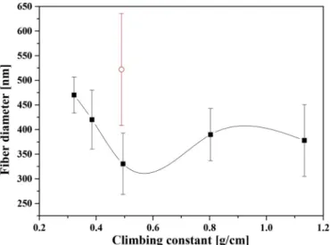
The relationship between climbing height and the squared rotation speed of the rod is shown in Fig. S3 h2(R) is obtained from the average value of the first-order derivatives of fitting curves when Ω2 is less than 10. In order to investigate the effect of the Weissenberg effect in elec- trospinning, we calculated the climbing constants using h2(R) obtained under different rod radii and solution concentrations (Table S2) ac- cording to Equation (4). Fig. 4 shows the effect of the climbing constant on fiber diameter. We found that fiber diameter tended to decrease when climbing constant increased. As mentioned at the beginning of this section, the climbing constant can be regarded as a parameter to describe the rheological properties of the polymer solution. If we ima- gine the physical meaning of the climbing constant from its unit (g/cm), it means the height of the polymer solution with a certain mass can reach driven by the Weissenberg effect. When the solution is more viscous (e.
g., with a larger viscosity), it can generate a slender solution column that climbs higher up the rod, which evidences that the climbing constant is smaller. Therefore, it is reasonable that a smaller climbing constant can result in thicker nanofibers, as presented in Fig. 4.
3.2. Formation of the meniscus driven by the Weissenberg effect 3.2.1. The formation of the meniscus
The climbing process and the formation of the meniscus are shown in
Fig. 5. Prior to applying high voltage, the rod was immersed in the PEO solution and rotated. In order to ensure that the polymer solution can climb up rod tip and completely cover that, we adjusted rotation speed to different values required by the different solution concentrations and rod radii. In this way, meniscus instability can be avoided and the electrospinning process is stable. During rotation, the polymer solution climbed gradually to the conical rod tip. The formation of the meniscus is depicted in Fig. 5a-f. Fig. 5a shows the clean rod tip before the rod began to rotate. At the beginning (in about the first 10 s), the solution climbed from the initial shape, and the shape of the rod tip coated by solution was changing into a triangle, as shown in Fig. 5b. As the solu- tion climbs higher, the shape of the solution coating the tip becomes more convex. Finally, a stable and conical envelope with a rounded tip is shown in Fig. 5f when the solution reached the rod tip. At this moment, high voltage was applied to the polymer solution, the envelope deformed towards the collector and its tip became sharper and sharper until a polymer jet was ejected from the vertex (Fig. 5g), indicating that the electric force was high enough to overcome the surface tension of the solution and an equilibrium was reached. Subsequently, the electro- spinning process turned into a steady-state, the initial jet ejected verti- cally towards the collector, and the meniscus also kept a stable conical geometry, as shown in Fig. 5h. Unfortunately, the radius of the initial jet after ejection from the meniscus vertex was too small to be captured precisely by our camera.
3.2.2. Characterization of the shape of the meniscus
For each sample, we captured the image of the steady meniscus. The camera recorded an axial symmetric geometry formed on the rod tip, which was in good agreement with our observations. We processed the images by MATLAB to obtain the dimensions of the meniscus in pixels.
Afterward, we converted the pixels into millimeters, and depicted the shape of the meniscus in a cylindrical coordinate system, as shown in Fig. 6a and b. We defined 4 parameters to characterize the shape of the meniscus:
3.2.2.1. Inflection point (I). As shown in Fig. 6c, the shape of the meniscus is composed of three zones, i.e. a linear zone, a concave zone and a convex zone. The convex zone can be originated from the Weis- senberg effect. After the voltage is applied to the solution, the meniscus is stretched and the concave zone is formed. When the electrical force is sufficient to balance the surface tension, the polymer jet is ejected from the meniscus vertex, therefore it is a linear zone. It is important to investigate the shape of the liquid surface. Therefore, point I1 and point I2 are defined as inflection points which are the boundary between the convex zone and the concave zone, as denoted in Fig. 6d. They were calculated from the fitting curve of the meniscus segment when the second derivative of the fitting equation was zero. Due to the symmet- rical shape, point I1 and point I2 can be denoted by the point I.
3.2.2.2. The ratio of meniscus volume and rod tip volume (KV). Volume ratio (KV) is defined as (Vt-VR)/VR, where Vt is the total volume including the solution at the tip and the conical tip itself, and VR is the volume of the rod tip. They can be represented by (5,6):
Vt¼ Z ΔHþl
0
πR2MðhÞdh (5)
VR¼5πR2
3 (6)
Where RM is the distance between the surface of the meniscus and the mid-line as denoted in Fig. 6c, h is the height of the meniscus, R is the radius of the rod, and l is the height of the rod-cone (5 mm).
3.2.2.3. The distance between the meniscus tip and the rod tip (ΔH).
Because of the resolution limitations of the camera and the optics used, Fig. 4. Correlation between the climbing constant and fiber diameter (the red
open circle is an outlier). (For interpretation of the references to colour in this figure legend, the reader is referred to the Web version of this article.)
the minimum size which can be captured was 0.02 mm (1 pixel). And in most of the sample images, the width of the meniscus at the highest point was about 1 pixel; there was no obvious difference. Therefore, the highest point captured by the camera was defined as a jet initialization point. The distance between the highest point O1 and the rod tip O3 is termed ΔH (see Fig. 6c), which is one of the parameters to describe the shape of the concave zone.
3.2.2.4. The ratio of the half-angle of the Taylor-cone to the vertex angle of the rod tip (ϕT). Taylor [6] pointed out that in needle electrospinning a thin polymer jet usually appears at the vertex of a conical droplet with an angle of 49.3�. It was later named Taylor-cone. To observe the angle of the Taylor-cone for rod-climbing electrospinning we had to record the
cone angle in each experiment. In this paper, the Taylor-cone angle was defined by the tangent lines to the meniscus body at the inflection point I, and the axis of symmetry at point O2. The Taylor-cone half-angle was used to describe the Taylor-cone. It is the angle between the tangent line and the symmetry line, as shown in Fig. 6d. Its tangent is the reciprocal of the first derivative at inflection point I. The Taylor-cone half-angle is also related to the size of the meniscus, which is influenced by the radius of the rod. We proposed ϕT as a new parameter to describe the Taylor-cone (7):
ϕT¼ θT
arctanðl=RÞ (7)
Where θT is the half-angle of the Taylor-cone, l is the height of the Fig. 5.The climbing process and meniscus formation on the tip of the rod (a–f), the start of the spinning process (g) and the steady-state of the spinning process (h).
7% PEO solution, 25 kV voltage, 2.5 mm rod diameter, 240 rpm.
Fig. 6. The principle of image processing: (a) the original optical image of the electrospinning process; (b) the segmented image after edge detection; (c) the meniscus edge curve of the projected profile; (d) the edge curve of the magnified protrusion above the inflection points.
conical tip of the rod, and R is the radius of the rod.
3.2.2.5. The ratio of the transition angle to the vertex angle of the rod tip (ϕTS). We introduced a new parameter, the transition angle, to quantify the slope of the transition from the meniscus to jet (from the concave zone to the linear zone). It can be calculated by (8):
θTS¼arctanðH=RTÞ (8)
where H is the height of the meniscus, and RT is the radius of the meniscus at the inflection point I. RT is a parameter depending on the radius of the rod. To compare the results obtained with different rods and eliminate the influence of rod radius, a relative parameter, the ratio of the transition angle to the vertex angle of the rod tip (ϕTS) is defined by (9):
ϕTS¼arctanðH=RTÞ
arctanðl=RÞ (9)
Where l (5 mm) is the height of the rod conical tip and R is the radius of the rod.
3.2.3. The relationship of the parameters of the meniscus and fiber diameter RC-ES is a fresh electrospinning method and the solution meniscus formed on the rod tip is important concerning the new method in this study. Table 2 summarizes the four parameters proposed in 3.2.2, which characterize the meniscus observed in various processing conditions.
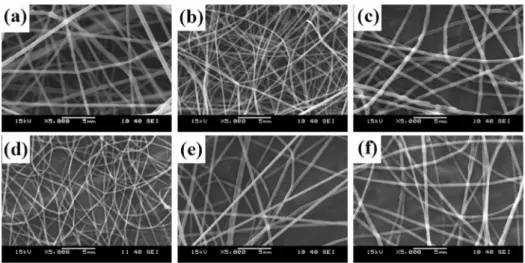
The morphology of some nanofiber samples obtained with the novel electrospinning method can be seen in Fig. 7. The diameters of nano- fibers produced were obtained from SEM images and summarized in Table 2. Fig. 8 shows the plots of fiber diameter as a function of different meniscus parameters; we used linear regression to estimate the slope.
The slopes indicate how strong the effect of the parameters is on fiber diameter. The results indicate that the four parameters can influence fiber morphology, indicating that meniscus shape can be an important factor affecting nanofiber diameter.
Fig. 8a reveals the correlation between the volume ratio of the so- lution climbing up to the rod tip and fiber diameter. Fiber diameter increased as the ratio of meniscus volume and rod tip volume increased.
Polymer solution concentration and voltage can also influence fiber diameter. However, they do not disturb the tendency of the effect of volume on fiber diameter, indicating that volume has a stronger effect on fiber diameter. It is probably because a larger meniscus surface re- sults in a smaller charge density, thus the repulsive force is insufficient to stretch the solution into a thinner jet from the tip.
Increasing distance between the meniscus tip and the rod tip (ΔH) reduces fiber diameter as shown in Fig. 8b. The solution meniscus on the rod tip was stretched more, which resulted in thinner fibers when ΔH
was larger. Besides, the stretching of the polymer solution is mainly controlled by the opposite effects of voltage and concentration. To verify the above-mentioned points, we compared the values of ΔH with the same voltage but different concentrations, and the same concentration and different voltages. We found that with the same concentration and the same rod, higher voltages resulted in larger values of ΔH caused by the larger electric forces. By contract, with the same voltage, higher concentrations resulted in smaller values of ΔH, due to higher solution viscosity.
Fig. 8c shows the effect of the Taylor-cone half-angle on fiber diameter. Theoretically, the semi-vertical angle of the Taylor-cone in needle electrospinning was close to the calculated equilibrium value of 49.3�[6]. The Taylor-cone angle obtained in this study was not a con- stant value, but a mutable parameter depending on other parameters. An increase in the Taylor-cone half-angle resulted in larger fiber diameter.
It can be explained with the definition of Taylor-cone in this study. It is the angle between the vertical axis and the tangent line of inflection point I, where its second derivative is zero. A larger Taylor-cone half-- angle means that the tangent line has a smaller slope. In other words, the shape of the meniscus is more convex, suggesting that greater stretching forces are needed to elongate the polymer solution into a thinner jet.
Meniscus shape can be determined by rod radius, the rotation speed of the rod and solution concentration, and other parameters.
The ratio of the transition angle to the vertex angle of the rod tip is also a parameter that can be used to predict fiber diameter. It has a positive relationship with fiber diameter, as shown in Fig. 8d. It is influenced by solution concentration and voltage. With a higher voltage, a larger transition angle was obtained. When solution concentration decreased, the transition angle increased.
4. Conclusion
In this paper, we utilized the Weissenberg effect in electrospinning, namely rod-climbing electrospinning, where a rotating rod is immersed in a polymer solution. The experimental results showed that the nano- fibers can be fabricated starting from the tip of the rotating rod. We investigated the climbing constant, which is an important rheological parameter to quantify the Weissenberg effect. The results showed that with an increase in the climbing constant, fiber diameters tended to decrease. We adopted a similar method characterizing the droplet re- ported by Liu et al. [13] in needle electrospinning for our new electro- spinning approach (RC-ES). The results showed that the average fiber diameter is influenced by the shape of the meniscus. The shape of the meniscus can be described with the shape parameters (i.e. ϕTS, ϕT, KV, ΔH). We found that the larger the ϕTS, ϕT, KV shape parameters are, the thicker the fibers become while increasing ΔH has the opposite effect.
Therefore, RC-ES will open interesting opportunities for developing new
Table 2
Fiber diameter from different electrospinning parameters.
Sample No. Parameters Results
Concentration [%] Rod radius [cm] Voltage [kV] Rotation speed [rpm] Kv [ ] ΔH [mm] ϕT [ ] ϕTS [ ] Fiber diameter [nm]
ES-1 6.0 3.5 25 350 3.839 1.536 – – 444.1
ES-2 6.0 3.5 35 350 1.755 2.005 1.704 1.029 409.6
ES-3 6.0 3.5 45 350 3.799 1.438 – – 338.5
ES-4 7.0 2.5 25 240 12.892 1.120 1.516 1.069 521.9
ES-5 7.0 2.5 35 240 9.690 0.755 0.806 2.276 490.3
ES-6 7.0 2.5 45 240 6.496 1.170 1.407 2.021 484.2
ES-7 7.0 3.5 25 260 2.796 0.798 1.411 1.536 448.1
ES-8 7.0 3.5 35 260 3.595 1.247 1.300 1.432 422.7
ES-9 7.0 3.5 45 260 2.798 1.399 – – 366.4
ES-10 7.0 5.0 25 150 0.341 3.137 0.841 2.282 377.9
ES-11 7.0 5.0 35 150 0.745 2.027 0.520 1.510 293.3
ES-12 7.0 5.0 45 150 0.578 1.715 1.636 0.993 422.1
ES-13 7.5 3.5 25 220 2.190 1.132 1.291 0.445 486.0
ES-14 7.5 3.5 35 220 1.856 2.579 1.291 0.845 405.4
ES-15 7.5 3.5 45 220 3.164 1.770 1.122 1.046 427.4
electrospinning methods where material properties (e.g. rheological properties) are exploited. In order to enhance productivity, we will focus on developing multiple jets from a single meniscus or using multiple rods.
Declaration of competing interest
The authors declare that they have no known competing financial
interests or personal relationships that could have appeared to influence the work reported in this paper.
CRediT authorship contribution statement
Haijun He: Conceptualization, Methodology, Formal analysis. Min Gao: Investigation, Writing - original draft. Daniel Torok: Software, Fig. 7.SEM images of nanofibers obtained with RC-ES: (a) ES-1, (b) ES-3, (c) ES-7, (d) ES-9, (e) ES-10, (f) ES-14.
Fig. 8. The effects of meniscus parameters on fiber diameter: (a) the ratio of meniscus volume to rod tip volume, (b) the distance between the tip of the meniscus and the tip of the rod, (c) the ratio of the half-angle of the Taylor-cone to the vertex angle of the rod tip, (d) the ratio of the transition angle to the vertex angle of the rod tip (solid squares indicate measured values fitted in the model, open circles indicate measured outliers of the model).
Data curation. Kolos Molnar: Writing - review & editing.
Acknowledgements
This work was supported by the Higher Education Excellence Pro- gram of the Ministry of Human Capacities in the framework of the Nanotechnology research area of the Budapest University of Technology and Economics (BME FIKP-NANO), the Hungarian Research Fund (OTKA FK 131882), the ÚNKP-17-4-I New National Excellence Program of the Ministry of Human Capacities, the ÚNKP-19-4 New National Excellence Program of the Ministry for Innovation and Technology and BME-KKP. This paper was also supported by the J�anos Bolyai Research Scholarship of the Hungarian Academy of Sciences (K. Moln�ar), Sti- pendium Hungaricum Scholarship of Tempus Public Foundation and China Scholarship Council (201700500073).
Appendix A. Supplementary data
Supplementary data to this article can be found online at https://doi.
org/10.1016/j.polymer.2020.122247.
References
[1] E. Hirsch, P. Vass, B. Demuth, Zs Petho, E. Bitay, S.K. Andersen, T. Vigh, G. Verreck, K. Molnar, Zs K. Nagy, Gy Marosi, Electrospinning scale-up and formulation development of PVA nanofibers aiming oral delivery of biopharmaceuticals, Express Polym. Lett. 13 (2019) 590–603.
[2] Y.F. Shih, M.Y. Chou, H.Y. Lian, L.R. Hsu, S.M. Chen-Wei, Highly transparent and impact-resistant PMMA nanocomposites reinforced by cellulose nanofibers of pineapple leaves modified by eco-friendly methods, Express Polym. Lett. 12 (2018) 844–854.
[3] D.H. Reneker, A.L. Yarin, Electrospinning jets and polymer nanofibers, Polymer 49 (2008) 2387–2425.
[4] F.R.S. Lord Rayleigh, On the equilibrium of liquid conducting masses charged with electricity, Philos. Magaz. Ser. 5 (14) (2009) 184–186.
[5] J. Zeleny, On the condition of instability of electrified drops, with applications to electrical discharge from liquid points, Proc. Camb. Phil. Soc. 18 (1915) 71–83.
[6] G.I. Taylor, Disintegration of water drops in an electric field, Proc. Roy. Soc. Lond.
A 280 (1964) 383–397.
[7] A.L. Yarin, S. Koombhongse, D.H. Reneker, Taylor-cone and jetting from liquid droplets in electrospinning of nanofibers, J. Appl. Phys. 90 (2001) 4836–4846.
[8] C.J. Thompson, G.G. Chase, A.L. Yarin, D.H. Reneker, Effects of parameters on nanofiber diameter determined from electrospinning model, Polymer 48 (2007) 6913–6922.
[9] N.M. Thoppey, R.E. Gorga, L.I. Clarke, J.R. Bochinski, Control of the electric field–polymer solution interaction by utilizing ultra-conductive fluids, Polymer 55 (2014) 6390–6398.
[10] F.J. Higuera, Breakup of a supported drop of a viscous conducting liquid in a uniform electric field, Phys. Rev. E 78 (2008), 016314.
[11] P.G. de Gennes, F. Brochard-Wyart, D. Quere, Capillarity and Wetting Phenomena:
Drops, Bubbles, Pearls, Waves, Springer, New York, 2010.
[12] D. Lukas, A. Sarkar, P. Pokorny, Self-organization of jets in electrospinning from free liquid surface: a generalized approach, J. Appl. Phys. 103 (2008), 084309.
[13] S. Liu, D.H. Reneker, Droplet-Jet shapes parameters predict electrospun polymer nanofiber diameter, Polymer 168 (2019) 155–168.
[14] E. Sch€affer, T. Thurn-Albrecht, T.P. Russell, U. Steiner, Electrically induced structure formation and pattern transfer, Nature 403 (2000) 874–877.
[15] M.D. Dickey, E. Collister, A. Raines, P. Tsiartas, T. Holcombe, S. Sreenivasan, R.
T. Bonnecaze, C.G. Willson, Photocurable pillar arrays formed via electrohydrodynamic instabilities, Chem. Mater. 18 (2006) 2043–2049.
[16] D. Wu, Z. Xiao, K. Siong, K.S. Teh, Z. Han, G. Luo, C. Shi, D. Sun, J. Zhao, L. Lin, High-throughput rod-induced electrospinning, J. Phys. D Appl. Phys. 49 (2016) 365302.
[17] G. Zheng, J. Jiang, X. Wang, W. Li, W. Zhong, S. Guo, Self-cleaning threaded rod spinneret for high-efficiency needleless electrospinning, Appl. Phys. A 124 (2018) 473.
[18] U.H. Shin, Y.L. Li, A. Paynter, K. Nartetamrongsutt, G.G. Chase, Vertical rod method for electrospinning polymer fibers, Polymer 65 (2015) 26–33.
[19] U.H. Shin, Y.L. Li, A. Paynter, K. Nartetamrongsutt, G.G. Chase, Microscopy analysis and production rate data for needleless vertical rods electrospinning parameters, Data in brief 5 (2015) 41–44.
[20] J. Holopainen, T. Penttinen, E. Santala, M. Ritala, Needleless electrospinning with twisted wire spinneret, Nanotechnology 26 (2015), 025301.
[21] F. Yalcinkaya, B. Yalcinkaya, J. Maryska, Preparation and characterization of polyvinyl butyral nanofibers containing silver nanoparticles, J. Mater. Sci. Chem.
Eng. 4 (2016) 8–12.
[22] P. Pokorny, P. Mikes, D. Lukas, Measurement of electronic current in liquid jet, in:
2nd Int. Conference Nanocon, Olomouc, Czech Rep. 2010, 2010, p. 282.
[23] H.J. Wang, B. Liu, W.L. Huang, Z. Lin, J. Luo, Y. Li, L. Zhuang, W. Wang, L.L. Jiang, Continuous needleless electrospinning of magnetic nanofibers from magnetization- induced self-assembling PVA/ferrofluid cone array, J. Magn. Magn Mater. 452 (2018) 1–4.
[24] H. He, Y. Kara, K. Molnar, In situ viscosity-controlled electrospinning with a low threshold voltage, Macromol. Mater. Eng., DOI: 10.1002/mame.201900349.
[25] D.D. Joseph, Fluid Dynamics of Viscoelastic Liquids, Nee York, 1990.
[26] J. Yoo, D.D. Joseph, G.S. Beavers, Higher-order theory of the Weissenberg effect, J. Fluid Mech. 92 (1979) 529–590.
[27] X. Mei, Q. Chen, S. Wang, W. Wang, D. Wu, D. Sun, The microscale Weissenberg effect for high viscosity solution pumping at the picoliter level, Nanoscale 10 (2018) 7127–7137.
[28] A. Kaye, The shape of a liquid surface between rotating concentric cylinders, Rheol.
Acta 12 (1973) 206–211.
[29] D.D. Joseph, G.S. Beavers, A. Cers, C. Dewald, A. Hoger, P.T. Than, climbing constants for various liquids, J. Rheol. 28 (1984) 325–345.