S I X T H S Y M P O S I U M O N B A L L I S T I C M I S S I L E A N D A E R O S P A C E T E C H N O L O G Y
PRACTICAL DESIGN CONSIDERATIONS AND THEIR IMPLICATIONS FOR HIGH MASS FRAC T ION, GLAS S
FILAMENT REINFORCED PLASTIC CASE MOTORS
Jack Elias
Aerojet-General Corporation Solid Rocket Plant Sacramento, C a l i f .
Abstract
Considerable knowledge and experience have been
accumulated concerning the design and fabrication of improved solid propellant rocket motors employing glass filament reinforced plastic as the motor case material. The purpose of this paper is to predict what the designer can expect in improved rocket performance with this new medium, to present the implications uncovered by this study, and to indicate the special areas where new development work w i l l be required.
The paper w i l l also indicate the better b a l l i s t i c parameters to select for the motor design in order to obtain the maximum benefits offered by the new medium. The information presented w i l l be based on detailed component designs, supported
partially by actual fabrication and testing.
Introduction
The principal advantages offered by glass filament reinforced plastics over homogenous metal alloys as rocket chamber material are: ( a ) high strength-to-density ratio and
(b) design f l e x i b i l i t y . In the latter category, the glass filament material has an inherent advantage. It is capable of being formed to suit exactly the strength requirements of the chamber without redundancy. In order to employ these advantages to maximum effect, the glass filament chamber must therefore be designed efficiently.
In the following analysis, a medium size motor was selected as the basis of study: 36 inches in diameter by 60 inches long. With an efficient loading density of 93%, this size motor w i l l hold approximately 3,000 lb of propellant.
The material selected for construction of the outer case was Type Ε Owens-Corning glass filament 20 end roving in composite
S I X T H S Y M P O S I U M O N B A L L I S T I C M I S S I L E A N D A E R O S P A C E T E C H N O L O G Y
with a moderate t emperature Epoxy resin. The winding pattern was comprised of circumferential and longitudinal layers over the cylindrical section, combined with a zero-hoop-stress con
tour requiring only longitudinal layers over the heads* The polar bosses were made of Type 6061, T-6 aluminum alloy.
Flange extensions of the bosses were embedded and wound in to the elastomeric liner-insulation composite. The liner material selected was high-density rubber, faced with a wash coat of rubber-base propellant restriction material compatible to
both the liner and the propellant. For the sake of simplicity, the weights of the chamber skirts were not included in the mass fraction studies.
Presentation of Data
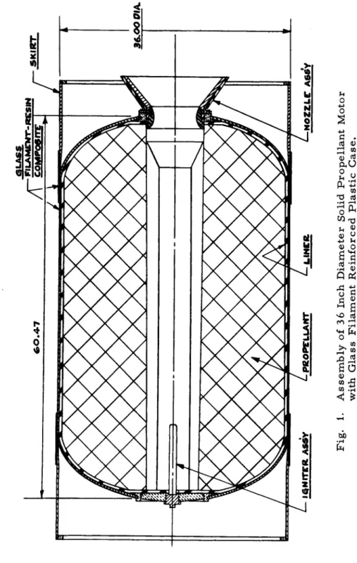
Figure 1 illustrates the general outline and features of the motor designed for this study. The chamber heads have zero-hoop-stress contours. The polar bosses are 30%
of the chamber diameter in size. The aft nozzle throat is of the submerged type, offering two major advantages: (1) This design shortens the length that the nozzle extends from the motor case. (2) It also minimizes the erosion on the aft chamber head by creating a boundary layer of gas to pro
tect the head against erosive gas flow. Skirt attachments are shown fore and aft to illustrate one type of possible attachment. This basic motor design was used to calculate the component parts weights that would be needed to operate the motor at the following average chamber pressures: 100 psia, 144 psia, 200 psia, 300 psia, 400 psia, and 500 psia.
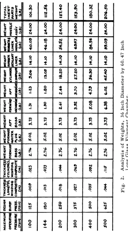
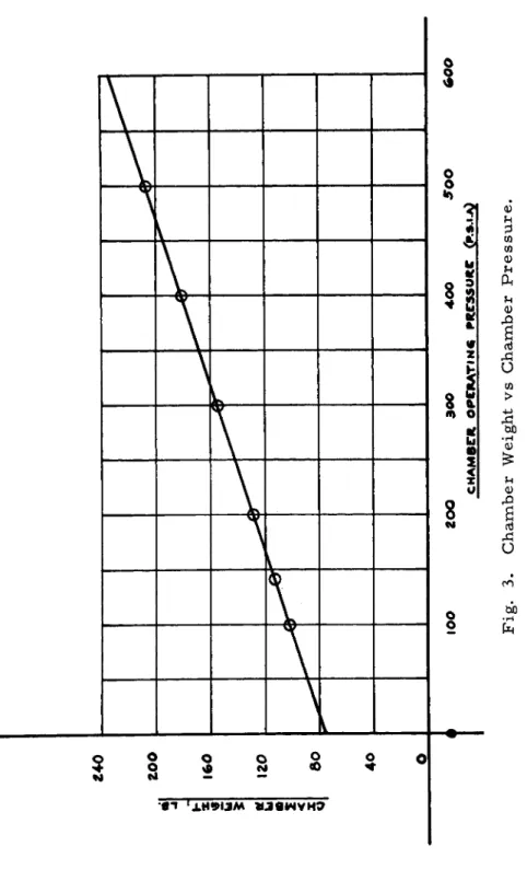
A breakdown of the component parts weights at each pressure is illustrated in Figure 2. To prove the accuracy of these weights, the 144-psia chamber was constructed and successfully hydrotested. A graphic illustration of chamber weight vs chamber operating pressure is illustrated in Figure 3. This graph emphasizes the efficiency of the glass filament
reinforced plastic as a rocket construction material, since even at the lower operating pressures, no redundant material is required and weight becomes a straight-line function of chamber pressure.
When this data is extrapolated and includes propellant and igniter weights, we find that the mass fraction of the entire motor also becomes a straight line function of chamber pressure, as illustrated in Figure 4. The achievement of high mass fraction with glass filament reinforced plastic material is therefore seen to be entirely possible even with
the current available knowledge. This achievement, of course, w i l l be more significant when propellants are developed
that can deliver high specific impulse at the lower pressures.
SIXTH SYMPOSIUM ON BALLISTIC MISSILE AND AEROSPACE TECHNOLOGY
4.
Fig. 1. Assembly of 36 Inch Diameter Solid Propellant Motor with Glass Filament Reinforced Plastic Case.
MAXIMUM OPERATING PRESSURE , <Ρ·Μΐ
OC5I6N BURST PRESS. CPSIA)
THICKNESS WINDING COMPOSITE OH) THICKNESS CYLINORCL WINDINQ COMPOSITE OH.)
WEI6HT FORWARP BOSS CL8.)
WEIGHT FORWARD IGNITER PLUG (US.)
WENS HT AFT Θ059 CLBO
WEIGHT FPRtVRP eu**1*
WEIGHT AFT MEMBRE CLS>
WEI6HT CYLINDER COMPOSAS (LB.) HTI4HT RUBBER SEALANT LINER αβ.) WEIGHT RU86EX4 LINER INSULATN (LB.)
WEI6HT NOZZLC ASSY
TOTAL iNrirr PARTS WEIGHT
ιο ο
125 .003 .023 5.02 3.73 1.31 1.23 3.06 I4.IO 40.03 a4.oo 101.3014 4
ΙβΟ .OI3 .033 2.76 5.02 3.73 1.30 1.80 I3.05 I4.IO 46.18 Z4.00 112.54 200 £50 .015 .0462 .7 6
5.02 3.73 2.61 2.46 18.20 14.10 ΖΛ.οο I27.40 300 375 .027 .063 2.76 5.02 3.73 3.32 3.70 Z7.20 I4.IO 63.47 Z4.0O I53.30 400 5Ο0 .035 .052 2.76 5.02 3.73 5.08 4.79 36.30 14.10 84.54 24.00 180.32 500 625 .044 .115 2.76 5.02 373 6386 .o e
45.40 14.10 39.09 24.00 Z0Ç>950 Fig. 2. Analysis of Weights, 36 Inch Diameter by 60. 47 Inch Long Glass Filament Chamber.SIXTH SYMPOSIUM ON BALLISTIC MISSILE AND AEROSPACE TECHNOLOGY
S I X T H S Y M P O S I U M O N B A L L I S T I C M I S S I L E A N D A E R O S P A C E T E C H N O L O G Y
Fig. 3. Chamber Weight vs Chamber Pressure.
Fig. 4. Mass Fraction vs Chamber Pressure.
S I X T H S Y M P O S I U M O N B A L L I S T I C M I S S I L E A N D A E R O S P A C E T E C H N O L O G Y
To illustrate this requirement, Figure 5 presents a plot of specific impulse vs chamber pressure for a modern, high-impulse propellant. The slope declines very sharply below 250 psia and recedes to negligible values below 100 psia.
At the other end of the curve, specific impulse increases very gradually above 500 psia, while mass fraction s t i l l increases at the same high rate as a straight-line function of chamber pressure.
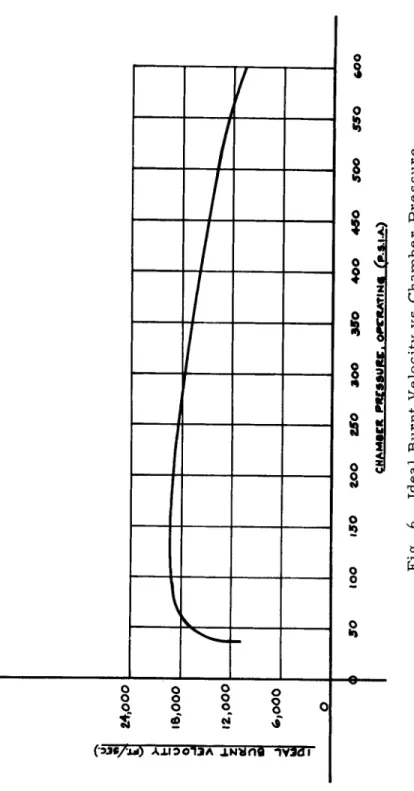
In order to give a truer picture of the actual performance of a rocket under the various conditions of mass fraction and propellant specific impulse, Figure 6 was calculated to show the slope of ideal burnt velocity. Using the designed inert parts, weights developed in Figure 2 and a propellant weight of approximately 3000 l b , we employ the following formula:
Wp + We Ideal Burnt Velocity = g χ Is χ ln
We
where g = acceleration of gravity, Is = specific impulse of the propellant at the various chamber pressures, Wp « propellant weight, and We = empty weight of the
rocket motor.
From this curve it is seen that the zenith of performance occurs at the approximate operating chamber pressure of 185 psia. It must be remembered, however, that this curve is based on an existing propellant that is more or less tailored
to operate most efficiently at pressures of 1,000 to 2,000 psia. With a propellant tailored to operate at lower chamber pressures, the ideal burnt velocity curve should improve mar
kedly as mass fraction increases.
To illustrate this point, Figure 7 was drawn combining the curves shown in Figures 4 through 6. Looking from the zenith of the burnt velocity curve towards the area of lower chamber pressure, it is noticeable that burnt velocity more or less follows the curve of specific impulse. From the zenith to the area of higher chamber pressure, it is seen that burnt velocity follows the line of mass fraction more closely.
If specific impulse at the lower chamber pressure values could be raised, it is evident that burnt velocity in the lower pressure values would also r i s e ; and therefore, the achievement of high mass fraction, which is already possible, would have more significance than i t does now. In the higher pressure ranges, i t seems apparent that mass fraction is even more significant in the achievement of high burnt velocity, and therefore the use of lighter weight construction materials more important.
For the sake of illustration, Figure 7 has also been divided into five zones as follows:
Zone A - the area of presently uncertain propellant
Fig. 5. Specific Impulse vs Chamber Pressure.
SIXTH SYMPOSIUM ON BALLISTIC MISSILE AND AEROSPACE TECHNOLOGY
Fig. 6. Ideal Burnt Velocity vs Chamber Pressure.
SIXTH SYMPOSIUM ON BALLISTIC MISSILE AND AEROSPACE TECHNOLOGY
81
Fig. 7. Composite Optimization Curve.
SIXTH SYMPOSIUM ON BALLISTIC MISSILE AND AEROSPACE TECHNOLOGY
S I X T H S Y M P O S I U M O N B A L L I S T I C M I S S I L E A N D A E R O S P A C E T E C H N O L O G Y
properties and low specific impulse.
Zone Β - the area of optimum performance under present
"state-of-the-art1 1 conditions.
Zones C and D - the areas of good and f a i r performance under present "state-of-the-art", where glass filament reinforced plastics are s t i l l superior to most steels in achieving high performance.
Zone Ε - the area of excessive weight losses, where the rocket performance delivered by glass filament reinforced plastic can be equalled or surpassed by many steels*
Even in Zone E, i t should be noted, glass filament
reinforced plastics may s t i l l have certain inherent advantages over steel, such as lower fabrication costs, less lead time from design to fabrication, and f l e x i b i l i t y of design.
The foregoing study has not considered the effect on mass fraction of such things as skirts, structural attachments and the need for exceptional structural rigidity to withstand unusual loading or shock, since these are variables that apply only in specific cases. For general purposes, i t is estimated that these factors, if they are efficiently built in to the chamber design, should not decrease the value of mass fraction by more than 0.03©
This study has been based on a "medium" size motor - 36 inches in diameter by 60 inches long. The values shown on the figures could be scaled up for motors of larger diameter, and down for motors of smaller diameter. The implications of the figures, however, would s t i l l be the same as those presented by the present figures. To summarize, the implications are as follows:
(a) Propellants must be developed to operate more efficiently at low chamber pressures, preferably within the range of 100 to 300 psia ·
(b) These propellants should also have good viscosity for casting through relatively small diameter openings.
(c) Better collapsible casting cores must be designed of any of the following types: (1) mechanical or folding umbrella type, (2) meltable type such as Cerrobend or wax and (3) frangible type such as Styrofoam, that can either be left in the motor or scraped out after casting.
(d) Better chamber reinforcements for structural strength should be employed such as lightweight honeycomb, hollow glass f i b e r s , foamed plastic, or plastic reinforcing r i b s .
(e) Improved methods for the attachment of chamber skirts, lugs, launch hooks, etc must be developed. The present "winding-in" method is adequate for limited purposes and relatively large dimensional tolerances©
( f ) A method of achieving larger diameter openings in
S I X T H S Y M P O S I U M O N B A L L I S T I C M I S S I L E A N D A E R O S P A C E T E C H N O L O G Y
the chamber heads without taking too great a weight penalty must be designed for applications where it is absolutely necessary - such as in segmented motors*
(g) Improved thrust termination methods should be originated to eliminate the need for multiple bosses on the chamber forward heads.
(h) New thrust vector control methods should be
developed also to eliminate the need for multiple bosses on the aft chamber heads* A promising method would be the
secondary injection of cold gasses directly into the exit cone to divert the thrust to the required vector.
( i ) There is also of course the obvious need to develop better fibers and better resins that are impervious to high temperature and pressure gas flow and that are compatible with the propellants they w i l l envelop.
Summary
The clue to higher performance motors employing glass filament reinforced plastic as a chamber construction material l i e s in:
(a) Operation of the motor at low chamber pressure (b) Efficient design of inert components
(c) Efficient grain design with good low-pressure propellant.
Ac knowledgements
This study is indebted to the Structural Materials Divi
sion of Aerojet under the direction of Mr. Edward L. Rucks, and specifically to Mr. Andrew Cecka and Mre Ralph Molho for their assistance in the design of the glass filament chambers and the construction of the test chamber.


