DOI: 10.1556/606.2019.14.2.21 Vol. 14, No. 2, pp. 235–246 (2019) www.akademiai.com
NEW APPROACH FOR ESTIMATION OF INCIDENT ENERGY ON HIGH VOLTAGE LEVEL
1 Bálint G. HALÁSZ*, 2 Bálint NÉMETH, 3 István KISS
1,2,3
Group of High Voltage Technology and Equipment of Department of Electric Power Engineering, Budapest University of Technology and Economics
Egry J. utca 18, H-1111 Budapest, Hungary
e-mail: 1halasz.balint@vet.bme.hu, 2nemeth.balint@vet.bme.hu, 3kiss.istvan@vet.bme.hu Received 2 January 2018; accepted 12 November 2018
Abstract: The purpose of this paper is to show a new calculation model, which is able to calculate the incident energy in any places near an electric arc in case of high voltage, without neglecting of length and position of the electric arc. This method is developed especially for the electric transmission network above 35 kV and several meters of gap distances. It would be used to estimate the thermal load of a power line worker close an initiated electric arc during live-line maintenance by bare-hand and hot stick method as well.
Keywords: Arc protection, High voltage, High current, Electric arc, Live-line maintenance
1. Introduction
The electric arc initiation in the relatively close environment of a worker is a complex source of danger: it has high temperature, which can exceed 20 000 °C.
Beyond that this temperature source can cause burns on human skin, it is able to cause the vaporization of the metal electrodes also, which are hot, toxic and can contain metal droplets from the endpoints of the arc. Additionally during the initiation between copper electrodes, the volume of the vaporized copper expands 67 000 times higher than it was in solid state. This amount of increase in volume means a high blast, pressure waves around the place of the arc. In addition to the high temperature and arc blast, the intense light phenomenon - named arc flash - can cause temporary or permanent blindness, while the sound energy is also significant. The electrical worker must be protected from
* Corresponding Author
these hazards in the adequate way, if there is any possibility of arc initiation in a working situation [1]-[2].
The initiation of an electric arc can cause different kind of complications, in which different approaches are needed to solve the problems as the novel researches show [2]- [5]. This paper focused on the protection of electrical workers from the thermal effects of electric arc, focused on long arcs (above 30 cm gap distance) in case of high voltage circumstances.
Several methods exist for the estimation of incident energy of an electric arc. These calculation methods have limits of usability regarding to the system voltage, available short circuit current, length of the arc gap, etc. The four calculated methods listed below are included by the Occupational Safety and Health Administration (OSHA) regulation about protection from flames and electric arcs:
• NFPA 70E-2012 Annex D (Lee equation);
• Doughty, Neal and Floyd;
• IEEE Std 1584b-2011;
• ARCPRO Software;
According to the Table-3 of the OSHA regulation [6], in case of voltage levels more than 15 kV, only the ARCPRO is acceptable [6]-[8]. Other calculation techniques are also exist: the Electric Power Research Institute (EPRI) has written a research about ‘arc flash issues in transmission and substation environments’, in which several hundreds of high current arc measurements were executed and introduced. Based on the measured values, empirical equations were developed for arc voltage gradient calculation and incident energy calculations [9].
In this paper, a new calculation method is introduced for the estimation of incident energy in case of high voltage systems (when system voltage is above 15 kV, and the arc length is higher than 30 cm).
2. Incident energy calculation via a new approach
In electrical field of science the solution of different kind of problems can be evaluated in different ways [10], [11]. During the setting up of this calculation methodology, the main principle was based on theoretical considerations to achieve the worst case situations in each examined scenario. Because of this approach, the results expected to be higher than the real values, but it has to be kept in mind, the real measured incident energy is stochastic; it always depends on the momentary circumstances.
The calculation needs the collection of input data. It is followed by the calculation of total energy of electric arc. The starting point is basically that: the total generated energy is the multiplication of the arc current, voltage and duration,
t I U
Eg = arc⋅ arc⋅ , (1)
where Eg is the total generated energy by the arc; Uarc is the voltage of the arc; Iarc is the arc current; t is the primer arc duration.
To define the voltage of electric arc, the most likely and authentic techniques were taken into account: The equation created by Goda et al. [12], and the equation from EPRI study [9]. Each of them was created based on measurements.
The voltage of the arc by Goda is [12]:
I l
Uarcrms ⋅
+
= 0.005 95 .
, 0 , (2)
where Uarc,rms is the root main square of the voltage in the electric arc; I is the arc current; l is the distance between the electrodes.
According to the EPRI study [9], the voltage can be determined as:
1255 . 1
0126 . 0 0069
. 0 19 . 1 000012
.
0 8 1.239
,
G I G
G U
arc rms
arc
⋅
⋅ + + ⋅ − ⋅
=
−
−
, (3)
where Iarc is the arc current, G is the distance between the electrodes.
A practicable solution for the calculation of arc current is the symmetrical component method [13]. In case of the current calculation, the result depends on the impedance of the fault, which could be expressed from the formulas of voltage gradient, but it depends on the fault current itself. To have wider safety margin, this arcing fault is expected to be a bolted fault, when the fault impedance is zero. The transient phenomenon at the initiation of fault current is neglected.
The duration of the arc basically depends on the operational characteristics and adjustments of the protective devices of network. It is commonly regulated by the national safety code of live-line maintenance. For example in case of Hungary, during live-line maintenance the maintained segment of the network must be in a special condition, so-called ‘hold-off state’, with special adjustments of protective devices. It means that automatic reclosers are deactivated and the tripping time is immediate.
Assumptions of the model are:
1) The power factor of electric arc is 1, which means the arc is a resistive part of the circuit;
2) In case of high voltage systems, the voltage of an electric arc is negligible compared to the nominal voltage of the network, therefore during this calculation the bolted fault current is assumed to be equivalent with the arc current. In case of low and medium voltage levels, the magnitude of arc voltage has the same magnitude as the system itself, the arc provides significant circuit resistance, therefore the arc current will be significantly different than the bolted fault current [7];
3) During the definition of the duration of electric arc, only the primer arc is taken into consideration from the initiation to the switching off the fault, any
malfunction is neglected, like the restrike phenomenon of high voltage circuit breakers;
4) The medium around the electric arc is lossless from the aspect of heat transfer. It is not the same with some approach, when it is assumed the heat is only emitted by radiation. It should be noted, in case of open-air arcs, called ‘radiated arcs’
[14], most of the energy is radiated via ultraviolet (UV), infrared radiation (IR) and visible light and a small percentage of convection, which takes this assumption realistic;
5) The total energy of the arc is emitted; the additional energy consuming phenomena are neglected, like the vaporization of electrodes and the heating of the vaporized metal;
6) The energy is emitted to the environment in all the direction.
In case of high voltage live-line maintenance, when the possibility of a flashover during the work has to be taken into account, the bare hand method, or hot stick method are widely used; during these works the power line worker is on high voltage potential or stands on the grounded part of the network. If the worst case scenario is expected, the worker is at the end of the electric arc, which means that the end point of the electric arc is less than half a meter away from the worker, while the length of the arc can be several meters. This arrangement does not allow the assumption that the energy source is point- like, because it is closer than the length of the arc, and the arrangement, the positions are also not negligible. Therefore this model should be extended for long line sources.
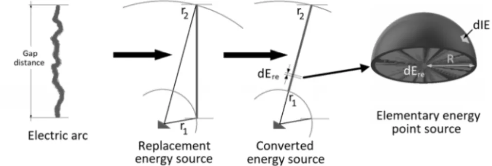
Considering the 4th, 5th, 6th assumptions, the energy emitting phenomena should be handled as a point energy source; therefore the effect on an elementary surface in the environment is shown in Fig. 1, energy per surface generated by the dEre elementary energy source is dIE in R distance. It can be calculated by (5), which is the base of the following step of the calculation:
1 2 r r
E dEre g
= − , (4)
( )
24 R R dE
dIE re
= π . (5)
In case of high voltage systems and the existing live-line technologies, the point-like energy source is not usable; therefore the model has to be extended to line sources:
( )
−
∫ =
∫ =
=
2 2 1
1 1 4 4
2 1 2
1 r r
dx dE R dx dE
x dIE
IE re
r r
re r
r π π . (6)
Eq. (6) can be used for one line energy source, which is radial to the examined surface, therefore a mathematical conversation is needed, when the electric arc - as a line energy source - can be replaced by other line electric sources; in this case the
calculation can be done. The whole generated energy of the electric arc is represented by a replacement line with a converted energy per length value; the total generated energy is equal, but it is divided by the length of the replacement line source. The closer and farer end of the arc and the replacement source is both in equal distance. If the loaded surface, which is examined from the aspect of incident energy, is at a higher or lower point than the electric arc, two replacement source have to be used, which means the modeling of any situation has to be done by this conversation.
Fig. 1. Conversation of the electric arc to line energy source and the division of the line source to point energy sources
3. Correction factors
The meandering behavior of electric arcs is a well-known phenomenon. The observations and experiments also show that, especially in case of high voltage systems, significant increase can be caused in the arc length (not the same as the gap distance) due to electromagnetic forces and the high temperature induced effects, after the arc initiation. If the power line worker stays close to the electric arc, the arc probably move closer towards the worker, which can mean significantly higher incident energy [15].
Because of that, if the expected place of the arc is within half meter around the worker, it should be considered. In vertical gap case, after 20 ms from the initiation, when the condition, place and path is different from the initiative state, two symmetrically arranged replacement energy sources should be used for modeling the phenomena: one is 10 cm closer, and the other is 10 cm away. The manifested energy by one of the new arc replacements in the modified arrangement is the half of the total generated energy, which means the sum is not changed. Because of the meandering behavior, in case of vertical and open air gaps, this calculation method is usable when the total arc duration is maximum 100-200 ms.
In hundreds of milliseconds, probably the electric arcs path can be significantly different from the initiative state, as it is illustrated in Fig. 2. Moreover in case of different electrode arrangements, current path and the direction and size of electric arc are able to be significantly different also. As it is stated in the regarding researches, and based on the phenomenon in which the flowing current make the current carrier loop
widen, the real incident energy will always depend on the exact arrangement [15]. In these situations, the place of the replacement energy source should be changed.
It is highlighted; the voltage gradient of long electric arcs is not homogeneous along the whole arc: the arc jets (approximately 50 cm from the ends of the arc) have higher voltage per meter value than the arc column between the two arc jets [6]. One reason of this difference might be the energy, which is needed for melting, vaporization of electrodes and the heating of the gas vaporized from the electrodes. This energy is involved from the total generated energy from the electric arc, which can theoretically mean less incident energy also.
Fig. 2. Behavior of a high voltage and high current electric arc based on available information [9], [12]
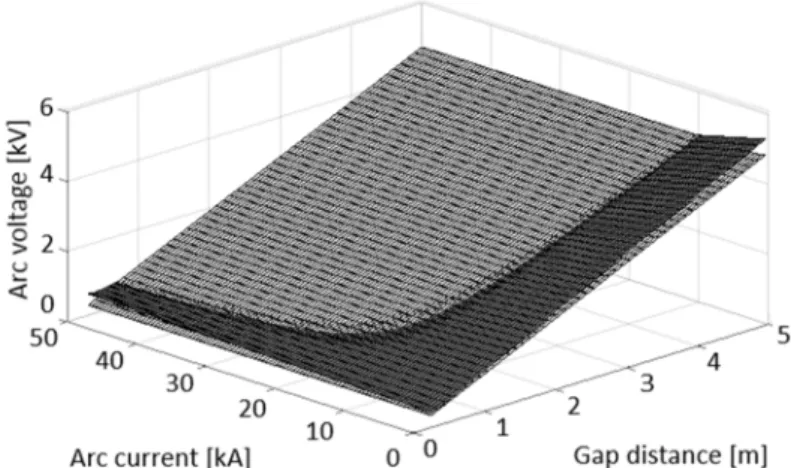
As Fig. 3 shows, in some ranges of arc current and gap distance (on the x and y axes), the equation from EPRI (dark grey plane) gives higher arc voltage values (on the z axis), while in the other cases the formula from Goda results higher voltages (light grey plane). It should be noted, the measurements from Goda et al. were executed with the gap distance of 3.4 m, while in the case of EPRI, it was changed between 30 cm (1 feet) to 150 cm (5 feet). From the aspect of the main aim of the development the worst case approach would give the safest result, therefore from the first approach in each case the higher voltage should be used.
4. Validation of the model
The measured and published raw data from the EPRI study was used for the validation of the model, to check the correlation between the measured values and the performed calculations on the same arrangements as the measurements were executed.
The published measurements were done with the following properties:
• Electrode material: aluminum, stainless steel, copper, graphite;
• Vertical electrode arrangement with different calorimeter positions;
• Gap length of 1, 2, 4, 5 feet (approx. 30, 60, 120, 150 cm);
• Bolted fault current of 8, 20, 40 kA;
• Arc duration of 2, 6, 12 cycles of 60 Hz sinusoidal current.
Fig. 3. Comparison of the EPRI arc voltage equation (light grey) with the formula from Goda arc voltage equation (dark grey); calculated arc voltage in function of arc current and
gap distance
The incident energy was measured by positioned calorimeters. The calorimeter is applied equipment in practice to measure the suffered energy in energy per area dimension. It is a copper plate, which contains thermocouples inside. The used calorimeters are marked in Fig. 4.
Fig. 4. One arrangement of the performed series by EPRI; the places of the calorimeters can be seen on the left, the drawing was produced by the EPRI study [12]
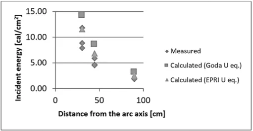
To validate the introduced model, calculations were done for each measured incident energy in each test series and these calculated and measured values were compared. In each case, the ratios were calculated between the calculated and measured cal/cm2 value. The case which is showed in Fig. 5 the gap distance was 5 feet (approx. 150 cm), the electrodes were made of stainless steel, the arc duration was 32.5 ms and arc current were 36.92 kA. The measurement and calculation were in the center line of the arc. As it can be seen, the measured values have deviation, and the calculations overestimate them.
Fig. 5. Comparison of the measured and calculated incident energy values with the use of the new model; The arc voltage is calculated by EPRI and Goda equation separately Calculations have been done on 579 measured values, and the statistical evaluation is shown in the Table I. This table contains the results of the calculation on the measured arrangements, in cases of aluminum and stainless steel electrodes only, and this table contains all the arrangements also (each positions of the calorimeters). It shows that the use of the new model involving the EPRI arc voltage calculation results 90% possibility of that the estimated incident energy value is between 90% and 200%
of the measured value. In case of copper and graphite electrodes, the calculated value was 3-5 times higher than the measured values.
5. Use of the developed model
The motivations of the described work are the accident cases that happened during live-line maintenance on high voltage network. Two of these accidents have happened in Canada in 1997 and 2002, on the 500 kV transmission networks [16]-[18]. The IEC 60895:2002 standard about conductive clothes - which must be worn in case of works when the power line worker would suffer high electric field exposure - does not contain any criteria about arc protection [19].
Table I
Statistical evaluation of the calculations Goda arc
voltage equation
EPRI arc voltage equation
Max (Goda;EPRI)
Measurements taken into account 579
Average Calc/Meas rate 142.26% 151.23% 157.13%
Absolute minimum Calc/Meas rate 49.30% 71.40% 74.39%
Absolute maximum Calc/Meas rate 269.49% 286.86% 286.86%
Higher than 200% Calc/Meas rate 7.60% 6.91% 10.88%
Less than 90% Calc/Meas rate 5.87% 3.11% 2.59%
The arrangement of one of the two accidents can be seen in Fig. 6. The work was executed on the right insulator of the V-sting, which suspends the triple bundle in the center phase. The power line worker was standing in the window of the tower and he was holding a so called hot-stick, which is an insulated, Fiberglass Reinforced Plastic (FRP) rod to work with it on live parts. During the work, a flashover occurred on the surface of the hot stick. The current of the fault had 5.8 kA peak values, which means 4.1 kA rms values, the length of the arc was approximately 3.5 m, the primer arc duration was 50 ms, and the position can be seen in Fig. 6, on the surface of the used hot stick, held by the power line worker in the window of the tower. The end point of the electric arc is assumed to be 10 cm away from the nearest body part of the line worker.
Fig. 6. The arrangement of the situation when an FRP hot stick was flashed over on 550 kV based on the published information [16]
The calculation has been done in two ways, with the use of both the equation (2) and (3), and because of that the power line worker was on a lower place as the electric arc, and not next to the arc column, no correction was done on the replacement source. In this case, the resulted incident energies were 2.55 cal/cm2 (2) and 2.73 cal/cm2 (3). It also should be noted, the magnitude of the occurring fault current is in close relation with the distance from the supplying substation. If the same calculation is done with 10 kA rms values, which is not an unrealistic value on the high voltage transmission networks, these incident energy values are 6.23 cal/cm2 (2) and 6.28 cal/cm2 (3).
According to the NFPA 70E 130.7(C)(1), it is stated the working personnel shall wear personal protective equipment against electric arc in the arc flash boundary [8], which means that in the investigated case arc protectional PPE should have been used.
6. Conclusion
A new methodology was introduced for the estimation of incident energy suffered by electrical worker, in case of high voltage networks. The calculation method contains the following steps:
• Collection of input parameters;
o Geometrical arrangement of the workplace, including the exact place of electric arc, length, direction and the working personnel;
o Bolted fault current at the place of electric arc;
o Possible duration of the electric arc;
• Calculation of the arc voltage by the equation from EPRI and Goda, and choose the higher for the following steps;
• Calculation of the total generated energy;
• Determination of the needed correction based on the duration and the arrangement;
• Determine the geometrical parameters of the replacement arrangement of electric arc;
• Calculation of the incident energy at the place of the closest point of the electrical worker.
Several hundreds of measured values were used for the validation, which showed that in case of aluminum and stainless steel electrodes, the calculated value is consequently 1-2 times higher, than the measured ones, while in case of graphite electrodes, this ratio is 3-5. The main reason of the deviation of measured incident energies on the same arrangements with the same type of electrodes is the stochastic behavior of the electric arc. To find out the exact reason of the phenomenon that result the difference related to the material of the electrodes, further investigations are required.
Based on the performed case study high voltage live-line maintenance the proper arc flash hazard assessment also should be performed and the use of proper Personal Protective Equipment (PPE) should be considered. From the aspect of the available PPE in the market, the thermal load range, which was resulted by the case study, can be handled by existing protective materials.
Open Access statement
This is an open-access article distributed under the terms of the Creative Commons Attribution 4.0 International License (https://creativecommons.org/licenses/by/4.0/), which permits unrestricted use, distribution, and reproduction in any medium, provided the original author and source are credited, a link to the CC License is provided, and changes - if any - are indicated. (SID_1)
References
[1] Lee R. H. The other electrical hazard: electric arc blast burns, IEEE Trans. Ind. Appl, Vol. IA-18, No. 3, 1982, pp. 246‒251.
[2] Wright A., Newbery P. G. Electric fuses, 3rd Edition, The Institution of Electrical Engineers, London, United Kingdom, 2004
[3] Magmood F., Elkalashy N. I., Lehtonen M. Modeling of flashover arcs in medium voltage networks dure to direct lightning strikes, Electrical Power and Energy Systems, Vol. 65, 2015, pp. 59‒69.
[4] Kanokbannakorn W., Hongesombut K., Teerakawanich N., Srisonphan S. Arc flash hazard in distribution system with distributed generation, Procedia Computer Science, Vol. 86, 2016, pp. 377‒380.
[5] Khakpour A., Uhrlandt D., Methling R. P., Gortschakow S., Franke S., Imani M. T., Weltmann K. D. Impact of temperature changing on voltage and power of an electric arc, Electric Power Systems Research, Vol. 143, 2017, pp. 73‒83.
[6] Regulation/Strandard 29CFR, Appendix E to subpart V of Part 1926 - Protection from flames and electric arcs, 1926, https://www.osha.gov/pls/oshaweb/owadisp.
show_document?p_table=STANDARDS&p_id=871, (last visited 23 April 2018).
[7] IEEE Std. 1584-2002, IEEE guide for performing arc-flash hazard calculations, 2002.
[8] NFPA 70E, Standard for electrical safety in the workplace, 2012.
[9] Arc flash issues in transmission and substation environments: Results from tests with long arcs, Technical Report, Electric Power Research Institute, 2011, Paper 1022632.
[10] Friedl G., Kuczmann M. Edge finite element method in case of high frequency simulations, Pollack Periodica, Vol. 10, No. 3, 2015, pp. 59‒70.
[11] Marcsa D., Kuczmann M. Parallel solution of an electrostatic field problem - case study, Pollack Periodica, Vol. 7. No. 2, 2012, pp. 25‒34, 2012.
[12] Goda Y., Iwata M., Ikeda K., Tanaka S. Arc voltage characteristics of high current fault, IEEE Transaction on Power Delivery, Vol. 15, No. 2, 2000, pp. 791‒795.
[13] Geszti P. O. Electric power systems, Vol. 1, (in Hungarian), Tankönyvkiadó, Budapest, 1986.
[14] Hoagland E., Golovkov M., Maurice C., Clark P. Clothing in arc flash: four types of arc exposure and the effect of moisture on garment appearance after an arc event, IEEE Transactions on Industry Applications, Vol. 50, No. 4, 2014, pp. 2370‒2374.
[15] Golovkov M., Schau H., Habil I. Effect of arc electrode geometry and distance on FR fabric protection properties against second degree skin burn, 2016 IEEE IAS Electrical Safety Workshop, Jacksonville, FL, USA, 6-11 March 2016, Doi: 10.1109/ ESW.2016.7499705.
[16] McDermid W., Swatek D. R., Bromley J. C. Progress in resolving flashovers of FRP hot sticks during EHV live line work, Conference Record on the 2004 IEEE International Symposium on Electrical Insulation, Indianapolis, IN USA, 19-22 September 2004, Doi: 10.1109/ELINSL.2004.1380690.
[17] McDermid W., Swatek D. R., Bromley J. C. FRP hot stick flashovers during EHV live line work, Conference on Electrical Insulation Conference and Electrical Manufacturing and Coil Winding Technology, Indianapolis, Indiana, USA, 25-25 September 2003, Doi:
10.1109/EICEMC.2003.1247844.
[18] McDermid W., Bromley J. C., Dodds D. J., Swatek D. R. Investigation of the flashover of a FRP hot stick while in use for live line work at 500 kV, IEEE Transactions on Power Delivery, Vol. 14, No. 3, July 1999, pp. 1158‒1166.
[19] Live working - Conducting clothing for use at nominal voltage up to 800 kV a.c. and +/- 600 kV d.c., IEC 60895 Standard, 2002
![Fig. 2. Behavior of a high voltage and high current electric arc based on available information [9], [12]](https://thumb-eu.123doks.com/thumbv2/9dokorg/1079967.72830/6.892.275.691.364.625/fig-behavior-voltage-current-electric-based-available-information.webp)
![Fig. 6. The arrangement of the situation when an FRP hot stick was flashed over on 550 kV based on the published information [16]](https://thumb-eu.123doks.com/thumbv2/9dokorg/1079967.72830/9.892.261.563.609.915/fig-arrangement-situation-stick-flashed-based-published-information.webp)
