SPLIT-STEP OPERATORS IN ABSOLUTE
COORDINATES FOR AN EFSSM SOLUTION METHOD OF THE GENERALIZED NONLINEAR SCHRÖDINGER
EQUATION
Görbe, Mihály 1*
1 Department of Science, GAMF Faculty of Engineering and Computer Science, John von Neumann University, Hungary
https://doi.org/10.47833/2021.1.CSC.002
Keywords:
Ultrashort light pulses Nonlinear pulse propagation Laser pulse modeling
Non-linear Schrödinger equation Exponential Fourier split-step method
Article history:
Received 10 Marc 2021 Revised 4 April 2021 Accepted 10 April 2021
Abstract
Exponential Fourier split-step methods (EFSSM) are widely employed nowadays in the numerical treatment of the generalized nonlinear Schrödinger equation, e.g. in the modeling of ultrashort light pulse propagation in nonlinear media. The derivation of such methods is straightforward for a normalized electric field wavefunction using normalized coordinates, i.e.
spatial units that depend on diffraction length and pulse length and temporal units that depend on pulse duration, and they may depend on several more characteristic measures, such as nonlinear length, dispersion length, peak electric field strength as well. However when testing simulation programs and comparing outputs with experimental data it is easier to use absolute coordinates and absolute electric fields. This paper derives the formulae of the EFSSM in recent paper [1] using absolute coordinates for absolute electric fields.
1 Introduction
The generalized nonlinear Schrödinger equation is the model of several natural phenomena, such as plasma soliton [2] and water wave propagation [3,4], and the topic of the current paper: the propagation of ultra-intense laser pulses in nonlinear media [5,6], and its special case, the generation of white light continuum from ultra-intense laser pulses.
The white light continuum, which is an effect of spectral broadening of ultra-intense laser pulses, is illustrated on Fig. 1.
(a) (b)
Figure 1. The input high intensity laser pulse represented at the bottom of graph (a) [7] has a narrow wavelength range, but as it propagates in a medium, it gets broader and broader, and this
broadness in the end can be seen even with the naked eye as the white color of the output light on picture (b) [7]. The white light is also resolved into the colors of the rainbow.
There are several advanced applications of the white light continuum, including optical coherence tomography [8,9], frequency metrology [10,11,12] and fluorescence lifetime imaging [13].
Of course, the extreme broad bandwidth of the white light continuum enables it to be very fast light source of optical communication [14,15,16], and it has advantages as the light source of photoacoustic gas sensing applications [17,18,19].
Modelling of white light continuum generation is therefore of great scientific and technical importance.
2 Exponential Fourier split-step method (EFSSM) for the solution of the generalized nonlinear Schrödinger equation
The form of the generalized nonlinear Schrödinger equation used in nonlinear optics for the cases without ionization is [1]
(1) where u = u(,,,) is the normalized space and time dependent evolving wavefunction of the light pulse to be determined, u0 is the normalized wavefunction of the input pulse. The coefficients are related to the linear and nonlinear optical properties of the pulse and the medium (0: central angular frequency, p: pulse e–1 length, Ldf: diffraction length, Lds: dispersion length, Lnl: nonlinear length). On the left hand side there is the derivative of u by , which is the normalized coordinate in the direction of propagation. The Laplace operators are computed in the directions perpendicular to the propagation, with normalized and variables. The temporal variable , is normalized too.
The numerical solution of this equation is possible using an exponential Fourier split-step method (EFSSM) [1]. The method takes steps in the direction in order to compute u(+) from u(). The step is split because of the handling of the terms of the right hand side of the equation separately, for example:
𝑢(𝜁 + Δ𝜁) ≈ 𝐸𝐶[Δ𝜁, 𝜁, 𝐸𝐵[Δ𝜁, 𝜁, 𝐸𝐴[Δ𝜁, 𝜁, 𝑢(𝜁)]]]
where EA, EB and EC are the solution operators of the differential equations having the following A, B, and C operators (so called split step operators) on their right hand sides:
𝐴 =𝑖
4(1 + 𝑖 𝜔0𝜏𝑝
𝜕
𝜕𝜏)
−1
(𝛻𝜒2+ 𝛻𝜓2) − 𝑖𝐿𝑑𝑓 𝐿𝑑𝑠
𝜕2
𝜕𝜏2 𝐵 = 𝑖 [𝐿𝑑𝑓
𝐿𝑛𝑙|𝑢|2] − 1 𝜔0𝜏𝑝[𝐿𝑑𝑓
𝐿𝑛𝑙
𝜕
𝜕𝜏|𝑢|2] 𝐶 = − 1
𝜔0𝜏𝑝[𝐿𝑑𝑓 𝐿𝑛𝑙|𝑢|2 𝜕
𝜕𝜏]
Here (A + B + C)u is just the right hand side of our original (1) equation.
The ordering of the solution operators in step splitting, and the step sizes influence the precision of the solution. The best step size-operator ordering pattern is [1]
𝑢(𝜁 + Δ𝜁) ≈
≈ 𝐸𝐴 [
Δ𝜁 4 , 𝜁 +3
4Δ𝜁, 𝐸𝑐 [
Δ𝜁
2 , 𝜁, 𝐸𝐴[Δ𝜁 4 , 𝜁 +2
4Δ𝜁, 𝐸𝐵[Δ𝜁, 𝜁, 𝐸𝐴[Δ𝜁 4 , 𝜁 +1
4Δ𝜁, 𝐸𝑐[Δ𝜁
2 , 𝜁, 𝐸𝐴[Δ𝜁
4 , 𝜁, 𝑢(𝜁)]]]]]
]]
𝜕𝑢
𝜕𝜁 = 𝑖
4 (1 + 𝑖 𝜔
0𝜏
𝑝𝜕
𝜕𝜏 )
−1
(𝛻
𝜒2+ 𝛻
𝜓2)𝑢 − 𝑖 𝐿
𝑑𝑓𝐿
𝑑𝑠𝜕
2𝑢
𝜕𝜏
2+ 𝑖 (1 + 𝑖 𝜔
0𝜏
𝑝𝜕
𝜕𝜏 ) 𝐿
𝑑𝑓𝐿
𝑛𝑙|𝑢|
2𝑢
3 Motivation
In order to easily compare the EFSSM solution to experimental data or simulation results from another numerical methods, electric field strength as the function of absolute spatial and temporal coordinates ℰ(𝑥, 𝑦, 𝑧, 𝑡) should be obtained. In [1] we are given the split-step operators and the full EFSSM method for a normalized wavefunction u in normalized coordinates, and the situation is further complicated by the presence of the diffraction length, dispersion length, nonlinear length measures, that depend on both medium and pulse properties. Therefore it is straightforward to derive the corresponding operators in absolute space and time coordinates, that operators give the absolute electric field strength function.
4 Derivation
To derive the operators outlined above, first I substituted the definition of the relative coordinates into (1): 𝜒 = 𝑥
𝑠𝑝, 𝜓 = 𝑦
𝑠𝑝, 𝜁 = 𝑧
𝐿𝑑𝑓 and 𝜏 = 𝑡
𝜏𝑝 (the latter definition is not present in [1]; sp: pulse e–1 spatial extent).
Now substitute the definitions of the diffraction length, dispersion length and the nonlinear length: 𝐿𝑑𝑓 =𝑘02𝑠𝑝2, 𝐿𝑑𝑠=2𝜏𝑘"𝑝2 and 𝐿𝑛𝑙=𝜔 𝑐
0𝑛2𝐼0 (k0: central wavenumber, k”: the group delay dispersion and n2: the nonlinear refractive index of the medium, I0: the peak intensity of the pulse), in order to separate the measures that characterize the pulse, and that characterize the medium.
Let’s divide by k0, and use the several possibilities to simplify:
(2) At this point it is useful to compare the results with another paper [20], where the pulse propagation equation reads:
𝜕𝐴
𝜕𝑧
=
𝑖2𝑘0
(1 +
𝑖𝜔0
𝜕
𝜕𝑡
)
−1(𝛻
𝑥2+ 𝛻
𝑦2)𝐴 −
𝑖2
𝑘"
𝜕2𝐴𝜕𝑡2
+
𝑖𝜔0𝑛2𝑐
(1 +
𝑖𝜔0
𝜕
𝜕𝑡
) |𝐴|
2𝐴
The only difference is the definition of the wavefunction, 𝐴 = √𝐼0𝑢. This definition makes it possible, to eliminate I0 in the last term, by absorbing it into the square term as |√𝐼0𝑢|2= |𝐴|2.
A is proportional to the electric field strength amplitude ℰ we are looking for. The latter is known to be in the form 𝐼 =1
2𝜖0𝑐𝑛|ℰ|2. The peak intensity is associated with the peak electric field amplitude:
𝐼0=1
2𝜖0𝑐𝑛|ℰ0|2. Substitute this into the (2):
The electric field amplitude ℰ = ℰ0⋅ 𝑢 can be obtained everywhere in the equation through multiplying by ℰ :
𝐿
𝑑𝑓𝜕𝑢
𝜕𝑧 = 𝑖
4 (1 + 𝑖 𝜔
0𝜕
𝜕𝑡 )
−1
𝑠
𝑝2(𝛻
𝑥2+ 𝛻
𝑦2)𝑢 − 𝑖 𝐿
𝑑𝑓𝐿
𝑑𝑠𝜏
𝑝2𝜕
2𝑢
𝜕𝑡
2+ 𝑖 (1 + 𝑖 𝜔
0𝜕
𝜕𝑡 ) 𝐿
𝑑𝑓𝐿
𝑛𝑙|𝑢|
2𝑢
𝑘
0𝑠
𝑝22
𝜕𝑢
𝜕𝑧 = 𝑖
4 (1 + 𝑖 𝜔
0𝜕
𝜕𝑡 )
−1
𝑠
𝑝2(𝛻
𝑥2+ 𝛻
𝑦2)𝑢 − 𝑖 𝑘
0𝑠
𝑝22 2𝜏
𝑝2𝑘"
𝜏
𝑝2𝜕
2𝑢
𝜕𝑡
2+ 𝑖 (1 + 𝑖 𝜔
0𝜕
𝜕𝑡 ) 𝑘
0𝑠
𝑝22 𝑐 𝜔
0𝑛
2𝐼
0|𝑢|
2𝑢
𝜕𝑢
𝜕𝑧 = 𝑖
2𝑘
0(1 + 𝑖 𝜔
0𝜕
𝜕𝑡 )
−1
(𝛻
𝑥2+ 𝛻
𝑦2)𝑢 − 𝑖 𝑘"
2
𝜕
2𝑢
𝜕𝑡
2+ 𝑖 (1 + 𝑖 𝜔
0𝜕
𝜕𝑡 ) 𝜔
0𝑛
2𝐼
0𝑐 |𝑢|
2𝑢
𝜕𝑢
𝜕𝑧 = 𝑖
2𝑘
0(1 + 𝑖 𝜔
0𝜕
𝜕𝑡 )
−1
(𝛻
𝑥2+ 𝛻
𝑦2)𝑢 − 𝑖 𝑘"
2
𝜕
2𝑢
𝜕𝑡
2+ 𝑖 (1 + 𝑖 𝜔
0𝜕
𝜕𝑡 ) 𝜔
0𝑛
21 2 𝜖
0𝑐𝑛
𝑐 |ℰ
0⋅ 𝑢|
2𝑢
(3) Now the A’, B’ and C’ operators of (3) can be constructed, whose sum applied on ℰ gives the right hand side of (3):
𝐴′(𝑥, 𝑦, 𝑡) = 𝑖
2𝑘0(1 + 𝑖 𝜔0
𝜕
𝜕𝑡)
−1
(𝛻𝑥2+ 𝛻𝑦2) −
𝑖 2 𝑘"
𝜕2
𝜕𝑡2 𝐵′(𝑥, 𝑦, 𝑡) = 𝜔0𝑛21
2𝜖0𝑛 [𝑖|ℰ|2− 1 𝜔0
𝜕
𝜕𝑡|ℰ|2]
𝐶′(𝑥, 𝑦, 𝑡) = −𝑛
21
2 𝜖
0𝑛|ℰ|
2𝜕
𝜕𝑡
5 Results and future work
With my colleague Balázs Antalicz at ELI-ALPS we have written a modeling program in Matlab, that implements the three-operator method derived above, with the step size-operator ordering pattern:
ℰ(𝑧 + Δz) ≈
≈ 𝐸𝐴′
[ Δz
4 , 𝑧 +3 4Δz, 𝐸𝑐′
[ Δz
2 , 𝑧, 𝐸𝐴′[Δz 4 , 𝑧
+2
4Δz, 𝐸𝐵′[Δz, 𝑧, 𝐸𝐴′[Δz 4 , 𝑧 +1
4Δz, 𝐸𝑐′[Δz
2 , 𝑧, 𝐸𝐴′[Δz
4 , 𝑧, ℰ(𝑧)]]]]]
]]
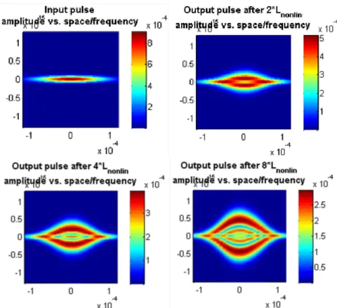
A few examples I generated using this code can be seen on Fig. 2. An ultra-intense laser pulse is taken into account propagating in fused silica (for quantitative properties see figure caption). The horizontal extent is the spatial size, the vertical is the spectrum, that broadens spectacularly as the pulse propagates forward.
𝜕ℰ
𝜕𝑧 = 𝑖
2𝑘
0(1 + 𝑖 𝜔
0𝜕
𝜕𝑡 )
−1
(𝛻
𝑥2+ 𝛻
𝑦2)ℰ − 𝑖 𝑘"
2
𝜕
2ℰ
𝜕𝑡
2+ 𝑖 (1 + 𝑖 𝜔
0𝜕
𝜕𝑡 ) 𝜔
0𝑛
21
2 𝜖
0𝑛|ℰ|
2ℰ
Figure 2. Ultra-intense light pulse propagation in fused silica. Central wavelength: 532 nm, input length: 30 fs, beam width: 100 µm, pulse energy: 200 mJ (peak field strength 2·1010 V/m)
My planned future task is to recreate the multiplate continuum-generation experiments in [20]
as simulations with an improved code, and then to investigate the effect of different types and extents of spatio-temporal couplings of the pulse on the output white light continuum.
Acknowledgment
This research is supported by EFOP-3.6.1-16-2016-00006 “The development and enhancement of the research potential at John von Neumann University” project. The Project is supported by the Hungarian Government and co-financed by the European Social Fund. Special thanks to Balázs Antalicz for working together on the modelling code and Ádám Börzsönyi at ELI- ALPS for the problem statement.
References
[1] Zia, Simulation of white light generation and near light bullets using a novel numerical technique, Commun.
Nonlinear. Sci. 54, 356-376 (2018) DOI: 10.1016/j.cnsns.2017.05.033
[2] Ruderman, Propagation of solitons of the Derivative Nonlinear Schrödinger equation in a plasma with fluctuating density, Phys. Plasmas 9, 2940–5 (2002) DOI: 10.1063/1.1482764
[3] Peregrine, Water waves, nonlinear Schrödinger equations and their solutions, J. Austral. Math. Soc. Ser. B 25, 16–
43 (1983) DOI: 10.1017/S0334270000003891
[4] Dysthe, Note on a modification to the nonlinear Schrodinger equation for application to deep water waves, waves Proc. R. Soc. Lond. A369: 105–114 (1979) DOI: 10.1098/rspa.1979.0154
[5] Gaeta, Catastrophic collapse of ultrashort pulses, Phys Rev Lett. 84, 3582-5 (2000) DOI:
10.1103/PhysRevLett.84.3582
[6] Anderson, Lisak, Nonlinear asymmetric self-phase modulation and self-steepening of pulses in long optical waveguides, Phys. Rev. A 27, 1393 (1983) DOI: 10.1103/PhysRevA.27.1393
[7] Paschotta, Supercontinuum Generation, in: RP Photonics Encyclopedia, https://www.rp- photonics.com/supercontinuum_generation.html, accessed on 2021-01-29
[8] Hartl, Li, Chudoba, Ghanta, Ko, Fujimoto, Ranka, Windeler, Ultrahigh-resolution optical coherence tomography
[9] Hsiung, Chen, Ko, Fujimoto, de Matos, Popov, Taylor, Gapontsev, Optical coherence tomography using a continuous-wave, high-power, Raman continuum light source, Opt. Express 12, 5287-5295 (2004) DOI:
10.1364/OPEX.12.005287
[10] Ranka, Windeler, Stentz, Visible continuum generation in air–silica microstructure optical fibers with anomalous dispersion at 800 nm, Opt. Lett. 25, 25-27 (2000) DOI: 10.1364/OL.25.000025
[11] Jones, Diddams, Ranka, Stentz, Windeler, Hall, Cundiff, Carrier-Envelope Phase Control of Femtosecond Mode- Locked Lasers and Direct Optical Frequency Synthesis, Science 288, 635-639 (2000) DOI:
10.1126/science.288.5466.635
[12] Schnatz, Hollberg, Optical frequency combs: From frequency metrology to optical phase control, IEEE Journal of Selected Topics in Quantum Electronics 9, 1041–1058 (2003) DOI: 10.1109/JSTQE.2003.819109
[13] Dunsby, Lanigan, McGinty, Elson, Requejo-Isidro, An electronically tunable ultrafast laser source applied to fluorescence imaging and fluorescence lifetime imaging microscopy, Journal of Physics D Applied Physics 3, 3296–
3303 (2004) DOI: 10.1088/0022-3727/37/23/011
[14] Takara, Ohara, Yamamoto, Masuda, Abe, Takahashi, Morioka, Field demonstration of over 1000-channel DWDM transmission with supercontinuum multi-carrier source, Electronics Letters 41, 270–271 (2005) DOI:
10.1049/el:20057011
[15] Morioka, Mori, Saruwatari, More than 100-wavelength-channel picosecond optical pulse generation from single laser source using supercontinuum in optical fibres, Electronics Letters 29, 862–864 (1993) DOI
10.1049/el:19930576
[16] Morioka, Takara, Kawanishi, Kamatani, Takiguchi, 1 Tbit/s (100 Gbit/s × 10 channel) OTDM/WDM transmission using a single supercontinuum WDM source, Electronics Letters 32, 906–907 (1996) DOI: 10.1049/el:19960604 [17] Delbarre, Tassou, Atmospheric gas trace detection with ultrashort pulses or white light continuum, in: Conference
Digest. 2000 Conference on Lasers and Electro-Optics Europe, Nice (2000) paper CWF104 DOI:
10.1109/CLEOE.2000.910121
[18] Sanders, Wavelength-agile fiber laser using group-velocity dispersion of pulsed super-continua and application to broadband absorption spectroscopy, Applied Physics B 75, 799–802 DOI: 10.1007/s00340-002-1044-z
[19] Ere-Tassou, Przygodzki, Fertein, Delbarre, Femtosecond laser source for real-time atmospheric gas sensing in the UV-visible, Opt. Commun. 220, 215–221 (2003) DOI: 10.1016/S0030-4018(03)01282-3
Cheng, Lu, Lin, Kung, Supercontinuum generation in a multi-plate medium, Opt. Express 24, 7224-7231 (2016) DOI:
10.1364/OE.24.007224
![Figure 1. The input high intensity laser pulse represented at the bottom of graph (a) [7] has a narrow wavelength range, but as it propagates in a medium, it gets broader and broader, and this](https://thumb-eu.123doks.com/thumbv2/9dokorg/750402.31616/1.892.170.734.881.1022/figure-intensity-represented-narrow-wavelength-propagates-broader-broader.webp)