Resilient Control Plane Design for Virtual Software Defined Networks
P´eter Babarczi, Member, IEEE
Abstract—Control plane survivability in virtual software- defined networks (vSDN) – where multiple tenants share the same physical infrastructure – is even more critical than in normal SDN networks. A reliable communication channel from the switches through the network hypervisor to the virtual controller is inevitable in order to avoid state inconsistencies, tenant isolation and security issues on the virtual switches.
Although reliable controller placement and control plane design was thoroughly investigated in SDNs, there was a lack of attention for resilient hypervisor placement and control path design for vSDNs. Therefore, in this paper we make a two-fold contribution towards a survivable vSDN control plane. First, we propose an approximation algorithm for (hypervisor) placement which – in contrast with traditional approaches which minimize the average latency to the hypervisors as an objective function – focuses on finding the appropriate number of hypervisor instances to satisfy the control path length constraints declared in the service level agreements, leaving enough options open for self-driving network designs and intelligent algorithms. Second, we propose a general dynamic program that calculates minimum length paths traversing specific type of nodes in a given order, and apply it to find control paths from the virtual controller of the slice to the virtual switches traversing the corresponding hypervisor location.
We conduct thorough simulations on real-world topologies to demonstrate the effectiveness of our approaches in no failure and single link failure scenarios.
Index Terms—virtual networks, resilient hypervisor placement, facility location, function chain routing, intelligent algorithms
I. INTRODUCTION
In the last decades communication networks transformed from a best-effort network connecting a handful of super- computers to a critical infrastructure connecting millions of devices. During this evolution the complexity of networks increased, and the management of nowadays Internet is a hard task for human operators and often leads to misconfiguration and service outages. However, network reliability is crucial both for mission-critical applications built on these networks (e.g., telesurgery) and for service providers to reach high Quality of Experience and hence, user satisfaction for their customers. These challenges fostered the concept of self- driving networks [1], which can react to unforeseen challenges in a timely manner without the need of human intervention.
The proliferation of Software Defined Networking (SDN) and network (function) virtualization eases the reconfiguration
The work of P. Babarczi was supported in part by Project no. 134604 that has been implemented with the support provided by the National Research, Development and Innovation Fund of Hungary, financed under the FK 20 funding scheme, and in part by the Alexander von Humboldt Foundation.
P. Babarczi is with the MTA-BME Future Internet Research Group, Dept. of Telecommunications and Media Informatics, Faculty of Electrical Engineering and Informatics (VIK), Budapest University of Technology and Economics (BME), Hungary (e-mail: babarczi@tmit.bme.hu).
of networks to respond to challenges, thus, providing enough flexibility [2] and tool-set for self-driving networks to control themselves based on their own observations and analysis of the network states. Therefore, “intelligent” algorithms are required for such self-driving networks to steer themselves into stable states upon traffic fluctuations or provide enough resilience against network failures [1]. By intelligence in this context we mean that the intrinsic motivation of these algorithms should be to keep as many future options open as possible (e.g., do not reserve or create bottlenecks), which can be used to react to unforeseen challenges [3]. Hence, intelligent algorithms need to be general enough and cannot rely on finely tuned objective functions tweaked to the current parameters of the network.
In virtual Software-Defined Networks (vSDN) multiple ten- ants share the same physical SDN network [4]. Each tenant is provided by a given slice of network resources (e.g., forwarding table space at switches, link bandwidth, CPU cores, etc.), where they can configure their virtual switches with their own controller and operate their own virtual network.
The network hypervisor layer (consists of a single or multi- ple hypervisor instances) ensures isolation (virtualization) of network attributes between different tenants, and also provides the abstraction of the reserved resources to the controller(s). In order to provide these functionalities, all control traffic of the slices between the switches and the controller goes through the hypervisor layer; therefore, even the failure of a single hypervisor instance could disrupt the traffic of several virtual networks. Although resilience of SDN transport networks against single link failures was thoroughly investigated [5], despite of its criticality hypervisor placement and control path resilience of vSDNs was barely considered. Hence, in this paper we will focus on this problem while we keep intelligent algorithm design and self-driving networks in mind.
It was shown [6]–[8] that the 50 ms recovery time re- quirement of carrier SDN networks can be achieved only if the switches do not have to contact the controller during the recovery process. Hence, protection paths have to be pre- computed and backup rules have to be deployed in the switches in advance of service disruptions both for data plane flows and in-band control plane paths. Thus, in this paper we will investigate the resilient hypervisor placement problem together with pre-calculating control paths for the virtual networks.
Instead of optimizing for a given objective function and finding the best possible placement, we are looking for a “good enough” solution which satisfies the service level agreements (SLA) and might leave enough options open for future self- driving designs and intelligent algorithms. We believe that the additional freedom provided by our approach (i.e., selecting from multiple acceptable hypervisor locations rather than
having a single one as the result of a fine-tuned optimization objective) can serve as the building block of these future networks.
The rest of the paper is organized as follows. Section II sum- marizes the related work on resilient control plane design. We formulate our problem in Section III and propose an algorithm based on minimum set cover for resilient hypervisor placement in Section IV. After the hypervisor locations are fixed, we investigate the problem of finding the controller location of dynamically arriving virtual network requests and calculate the corresponding unprotected and resilient control paths with a general dynamic program proposed for arbitrary function chains in Section V. Finally, we present our simulation results in Section VI and conclude the paper in Section VII.
II. RELATEDWORK
A. Pro-Active Resilient Control Path Design
It was shown that the strict 50 ms failure recovery time requirement (RFC 5654) for the data plane is achievable only if the recovery paths are pre-computed and established together with the working paths [6]. Although implementing protection approaches for single link failure resilience [9], [10] requires extra entries in the switches (using the group table concept), it avoids the sudden increase of traffic load on the single controller instance upon failure detection and loss of data packets due to the lengthy recovery time of the restoration approaches. This concept [6] was extended to in-band control channel failure recovery [11] for a single controller instance, as standard control traffic recovery time in OpenFlow falls in the order of seconds. As restoration of control traffic delays the restoration of data traffic as well (flow modification might be required at the disconnected switches), rapid recovery of control paths has utmost importance. Hence, an OpenFlow framework implementing in-band control with priority queuing and failure recovery functions was proposed [12]. Experiments were conducted, and shown that restoration of either data plane or control plane traffic does not allow achieving the 50 ms recovery time; hence, pro-active approaches are required [13].
Furthermore, as protection does not require controller inter- vention, it is less dependent on the network topology.
The design of an in-band routing tree spanning all switches and rooted at the single controller was investigated in [14].
Built on previous local route repair mechanisms from IP Fast- ReRoute (e.g., protection routing [15]) a primary tree and secondary (protection) next hops for each switch are designed, where the objective is to minimize the number of unprotected switches upon a single switch or link failure. However, the existence of a secondary next-hop which by-passes the parent switch along the tree is not guaranteed, i.e., full single failure coverage can not be provided. The concept was later extended to in-band trees rooted at different controller instances [16].
B. Resilient Controller Placement
In [17] resilient control plane design was investigated based on partitioning the network and assigning a controller to the centroid of each cluster in order to minimize control latency and the number of controller-less nodes upon link and node
failures. It is shown that finding an operating controller upon failure and reassigning the switch might lead to long outages and performance degradation owing to the increased load (i.e., queuing delay) at some controllers. Thus, pro-actively designing a list of backup controllers to each switch and auxiliary connections towards them might be beneficial [18].
Resilient controller placement was thoroughly investigated in [19], where the authors considered controller failures, network disruptions affecting in-band communication chan- nels, load-balancing of the traffic on each controller instance and inter-controller latency as objectives. The multi-objective framework provides Pareto-optimal solutions by an exhaustive evaluation of the design space for the combination of these design goals in small- and moderate-size network topologies, and allows network operators to choose the most appropriate solution to their requirements. For large scale topologies where the exhaustive search is not possible owing to mem- ory constraints, or for dynamically changing environments where prompt reconfiguration of controller placement might be needed a heuristic approach is proposed [20] based on Pareto simulated annealing for providing a solution in a timely manner for the placement of a fixed numberkof controllers.
Joint optimization of placement of multiple controllers and disjoint in-band control path design to the same controller instance or to two different controller locations was tackled in [5] (similarly as choosingKserver locations connected with disjoint path-pairs in optical grids/clouds [21]). Although from a scalability perspective it requires much more forwarding table entries than a single control tree, with this approach all single link and node (switch or controller) failures can be protected.
C. Hypervisor Placement Problem
Although data plane virtualization has been thoroughly investigated, [22] was the first work which introduced flex- ible control plane virtualization techniques. A comprehensive survey of different network hypervisors was presented in [4], and they were categorized based on their architecture (i.e., centralized or distributed) and their execute platform (i.e., software programs on general compute platforms and special- purpose network elements). As the control plane performance impacts the data plane performance, besides abstraction of resources the hypervisor should provide the isolation of both data- and control plane traffic of different tenants.
In [23], [24] the Hypervisor Placement Problem (HPP) was considered, where all virtual networks – set of virtual switches and their controllers – are known in advance and are given as input (i.e., off-line problem), and the task is to find the number and locations of hypervisors which minimizes maximum or average latency both for all control paths and per individual virtual network. In order to avoid control conflicts and state inconsistencies,each physical SDN switch should be controlled by a single hypervisor instance in the distributed single-controller switch architecture [24] investigated in our paper. In [25] it was demonstrated that with fixing hypervisors first and determining controller locations in a second step could lead to a better performance than vice versa [24] in
s
s h1 c
s h2 h3 s
h4
Fig. 1. Network locations (V) hosting both a physical switch and a server to run hypervisors and/or controllers. Four hypervisorsh1−h4 are deployed, each responsible for a disjoint set of physical switches (marked with clouds).
A possible virtual SDN embedding is shown with four virtual switches s and virtual controller locationcwith the corresponding switch-to-hypervisor (solid) and hypervisor-to-controller (dashed) pre-allocated control paths.
some networks, while a joint optimization of both controller and hypervisor locations would yield to the best performance among the three approaches. Therefore, we will use these observations in our resilient placement problem for the on- line case where virtual network requests arriving one after the other. The disjoint set of physical switches controlled by their assigned hypervisor are marked with clouds in Fig. 1. After the hypervisors are placed, we find the controller location for a set of switches of a single virtual network request in a second step, and design resilient control channels in the form of link- disjoint paths between them.
Although resilient controller placement is a well investi- gated topic, to the best of our knowledge, our work is the first which considers resilient hypervisor placement and in-band control channel design pro-actively before the failure occurs.
A re-active approach called Dynamic Hypervisor Placement Problem was proposed in [26], where the embedding of virtual networks might be changed owing to a disaster alert [27], which requires the redesign of the control plane and hypervisor assignment. Two approaches were investigated [27], namely when the virtual network to hypervisor assignment is fixed but the hypervisor can be migrated, and when the hypervisor assignments are fixed but the virtual networks can be reas- signed to different hypervisors. However, these methods are not suitable for the instantaneous reaction to link failures on the control path.
Minimizing the latency of the switches to the controller(s) or hypervisor(s) as a single objective optimization boils down to the traditional mathematical problem of facility location.
The closest to our work is [28], where the idea of using set cover for the disjoint-path facility location problem was used for Internet traffic monitoring and content distribution.
In [28] each customer must be served by two locations and be connected on shortest disjoint paths. It is proved that no polynomial-time algorithm can guarantee good solutions for the problem, and efficient heuristic algorithms are proposed.
In contrast to [23]–[27] minimizing for (average) control path lengths with complex Integer Linear Programs (ILPs), in our novel resilient self-driving control-plane design we will propose a polynomial-time placement algorithm without
using any task-specific objectives, without relying on a pre- defined number of hypervisor instances or having a priori knowledge about virtual network demands. As a result the resilient control path lengths will not be optimal in our hypervisor placement but still satisfy the SLAs for all (future) virtual networks where possible. Furthermore, in the dynami- cally changing network environment considered in this paper (i.e., link failures, unknown future vSDN requests) intelligent algorithms and heuristics which leave enough options open and have low computational complexity are required for the flexible reconfiguration of the network when a new placement is needed suddenly, e.g., in reaction to hypervisor failures, disaster alerts or load imbalance on the hypervisors.
D. Function Chain Routing Algorithms
With the proliferation of SDN and virtualization techniques, shortest path routing problems traversing specific types of functions in a given order (calledfunction chains) to enforce security policies or visiting ordered sequence of middle- boxes [29] become a hot research topic. Although the problem is hard on general network topologies if capacity constraints have to be fulfilled along the links for data plane traffic, in [29] the authors characterize the families of graphs for which polynomial-time algorithms exist. In [30] a Lagrange- relaxation technique was applied for the constrained shortest path problem, i.e., find shortest paths visiting nodes in a specific order. However, the proposed methods cannot guaran- tee link-disjointness of different segments of the paths; thus, cannot be used for resilient routing.
Resilient allocation of whole functions chains (i.e., joint optimization for placement and control path design) was investigated in [31], [32] against both single link and node failures. In [31] three ILPs were proposed to solve the virtual network function (VNF) placement and resilient control path allocation problem for different failure scenarios. In [32] the service is decomposed into possible realizations of the chain, and in a second step one of the realizations is embedded into the physical substrate using a backtracking algorithm.
For the latter problem, backup paths are calculated between two subsequent VNFs, between their backups and between a primary VNF and the backup of its subsequent one in the function chain. With this approach, failure resilience can be ensured upon physical node failures hosting a given VNF. Al- though these general methods would be applicable in our case, they use complex ILPs with fine-tuned objective functions to solve the problem. In contrast, in our hypervisor placement problem we use a polynomial-time algorithm built on minimal set cover, which can be used in self-driving networks as well. Furthermore, in our control path design problem we can exploit the special structure of paths for the virtual network slices (i.e., our function chains consist of switch-to-hypervisor- to-controller paths), resulting in faster algorithms.
On one hand, fully link- and node-disjoint paths can guaran- tee 100% resilience against single failures. On the other hand, in several use cases sharing some common elements of the paths might be beneficial. For example, formal language con- strained routing can be used to find shortest paths traversing
s c
h
P1(s, h) P2(s, h) P1(h, c) P2(h, c)
(a) Logical view
s c
x h
(b) Physical view Fig. 2. Pre-allocated link-disjoint control paths between the switch and hypervisor, and the hypervisor and the virtual controller in our resilient control plane. The shortest control path in the no failure case is shown with dotted lines. Note that, a single link failure(x, h)might affect multiple paths.
given links (even multiple times) [33], or common links in the disjoint path-pair can be allowed to reduce routing cost while a certain level of availability is maintained [34]. These concepts were extended for link-disjoint problems, where the paths can share minimum, maximum or exactlyk nodes, and it was shown that only the upper-bound problem is solvable in polynomial-time [35]. The authors introduced a dynamic program for the above problem variants, as well as for the task when the primary path of the connection is already part of the input, and the goal is to find a secondary path sharing a given number of common nodes with it [35].
E. Our Contribution
In this paper we propose an intelligent self-driving frame- work which pro-actively designs the resilient control paths for dynamically arriving vSDN requests. First, in Section IV we extend the concepts of resilient (controller) placement and control path design [5] with set cover [28] to our resilient hypervisor placement problem. However, in contrast with [5]
we do not fix the number of hypervisors in advance and in contrast with [28] we calculate resilient paths to a single location. In our model the hypervisor locations are selected based on the length of the link-disjoint path-pair to their controlled physical switches, which differentiates our work from [23], [28]. Furthermore, considering dynamic vSDN requests sets apart our placement model from [24], [25], where all requests are given as the input of the problem. Second, after the hypervisor location(s) are fixed, we use a dynamic program extending the concept of [35] to support the control path design of dynamically arriving virtual network requests in Section V.
III. PROBLEMFORMULATION
As we have seen, pro-active design of backup SDN control paths [11]–[13], [17], [18] are required if we want to meet the strict timing requirements declared in the service level agreements. This statement holds for vSDNs as well, where all control traffic between the virtual switches and its controller needs to traverse (one of) the hypervisor(s). Hence, in this
TABLE I
NOTATIONLIST FOR THERESILIENTCONTROLPLANEDESIGNPROBLEM
Notations Description
G(V, E) directed graph with node setV, link setE, and link lengthsl(e)∈R+ P(v1, vp) path (ordered sequence of links) from nodev1
tovp, with lengthl(P) =P
e∈P(v1,vp)l(e) nodeDistance() resilient control distance of nodes calculated as
the average length of a disjoint path-pair L maximum allowed switch-to-hypervisor distance hs∈ H hypervisorhs responsible for physical switchs
from the set of hypervisor locationsH N(h) set of physical switches within control distance≤Lto hypervisor locationh S(s) set of candidate hypervisor locations which can
serve physical switchs(i.e., distance≤L) I(h) number of switchesswithin distance≤Ltoh
without candidate hypervisors (i.e.,S(s) =∅) R ⊆V set of nodes representing the virtual switch
locations of an embedded virtual network request D sum of all switch-to-hypervisor-to-controller
distances for virtual network requestR Vf ⊆V locations hosting network function typef d[i][v][f] path length fromstovwith at mostilinks that
visits network functions inV1, . . . , Vf in order π[i][v][f] last node on pathstovwith at mostilinks that
visits network functions inV1, . . . , Vf in order
paper we pro-actively design the resilient control paths for each slice.
Most of the works assume that control paths are either out-of-band or control traffic has high priority even with in- band control [5], [19], [23], [24], [28]. Built on this fact, the most important difference of our control plane design approach compared to data plane design methods and complexity results there [29] is that we do not consider link capacities in our formulations [5], [24]. Note that, without these constraints the control paths of different switches do not influence each other, hence, can be calculated independently, which provides us the opportunity for an intelligent algorithm design and improved complexity results.
A. Resilient Control Plane Model
A network is represented by a directed graph G(V, E), whereV is the set of nodes and E is the set of links. Each nodev∈V represents a physical location in the network with a physical SDN switch. Furthermore, we assume that each location can host virtual network functions such as hypervisors or controllers. Each link e = (u, v) ∈ E is assigned with a positive length l(u, v) ∈ R+ which can represent physical length or delay. A path P(v1, vp) is an ordered sequence of links< e1= (v1, v2), e2= (v2, v3), . . . , ep−1= (vp−1, vp)>
which provides a communications channel between v1 and vp. The total length of a path l(P) is the sum of the link’s lengths in the path. We assume symmetric links, i.e.,
∀e= (u, v)∈E:l(u, v) =l(v, u), thus, the minimum length (i.e., shortest) paths are the same in both directions. Hence, we will calculate the control path only in one direction, but we assume these channels are bidirectional, as well as a link failure affects both directions at the same time. The notations used throughout the paper are summarized in Table I.
In Fig. 2 we present the considered architecture [24]
in this paper. We assume pre-allocated link-disjoint control paths between the locations, which can be calculated in advance (consequence of no link capacity constraints), shown in Fig. 2(a). Assuming that l(P1(s, h)) ≤ l(P2(s, h)) and l(P2(h, c)) ≤ l(P1(h, c)), the actual control path in the no failure case is shown with dotted lines. However, if a link failure occurs along this path, the control flow must be rerouted to the other one. Hence, as both lengths impact the overall performance of the virtual network, we will consider the average length of these paths in our algorithms.
Definition 1. FunctionnodeDistance(s, h)represents the resilient control distance between nodessand h, defined as
nodeDistance(s, h)= [l(P1(s, h)) +l(P2(s, h))]/2.
Note that, for the shortest P∗(s, h) path: l(P∗) ≤ nodeDistance(s, h), where equality holds when both paths in the disjoint path-pair are shortest P(s, h)paths.
B. Reaction to Single Link and Hypervisor Failures
One can observe that in our resilient design both the switch- to-hypervisor and hypervisor-to-controller control channel is a disjoint path-pair by the definition. Although a single link failure can disrupt one of the paths of the path-pairs for both channels if they share a common link (e.g., link (x, h) Fig. 2(b)), a pre-configured control path will still remain to satisfy our resiliency requirement. We assume the same fail- over mechanisms to the pre-calculated backup path upon link failure as previous control plane design approaches for SDN networks [5], [12] or traditional protection approaches. Sim- ilarly to data plane traffic, the pre-installed backup resources can be used in the no failure case to forward low-priority traffic or for load-balancing purposes.
As each hypervisor is responsible for a disjoint partition of physical switches [24] as shown in Fig. 1, its failure will affect only the isolation and abstraction of the virtual networks running on these switches. Although it would be possible to rerun a HPP algorithm to recalculate a whole switch-to- hypervisor assignment, creating new partitions of the network controlled by new hypervisor instances at new locations would cause unnecessary disruptions for all tenants with running virtual networks. Instead of this, we either suggest to migrate the hypervisor to a different location within the partition if the disruption can be forecasted [27], or run an HPP algorithm only to the subset of physical switches which were assigned to the failed hypervisor. Note that, owing to the increased shortest path lengths caused by the node failure, there might be multiple new partitions as well.
C. Intelligent Self-Driving Network Operation
In our model self-driving networks are measure, analyze and control themselves and are able to react to changes in the environment (e.g., network failures or new vSDN requests in our case) based on their observations. In such dynamic environment having multiple options to choose from in response to unknown challenges is inevitable, as well as
the ability to instantaneously realize this potential. Being prepared for the future – i.e., maximizing the number of options – is a desired property and well-investigated area in communication networks as well (e.g., in resilience), and several definitions agree that such behaviour is considered to be intelligent [1], [3]. On the one hand, this can be achieved in a self-driving manner with algorithms that aim to maximize preparedness as an intrinsic motivation, without relying on comprehensive mathematical models or task-specific objective functions. For example, minimum interference routing [36]
keeps bottleneck resources open, which makes more unknown connection requests acceptable in the future without having it as an explicit objective.
On the other hand, without the knowledge of such intrinsic motivation (e.g., in case of our placement problem in Sec- tion IV), a weaker approach can be used and formulate the problem in a way that several states satisfy the constraints the self-driving network can choose from in response to changes (in contrast with the single solution of an optimization problem with fine-tuned objective). We note that the algorithm which solves this intelligent formulation can be an optimization method if the parameters should not be tweaked on a case- by-case basis, and if the increased complexity still suits the reaction time requirements of the self-driving network.
IV. HYPERVISORPLACEMENT WITHGREEDYSETCOVER
In this section we propose a polynomial-time algorithm to the resilient hypervisor placement problem, and show that it approximates the optimal solution in terms of the number of hypervisors. Formally, the problem is defined as follows:
Problem 1. Resilient Hypervisor Placement: Given a net- work G(V, E), link lengths l(u, v), and constraint L on the maximum switch-to-hypervisor distance. Find a minimum number of hypervisor locationsH ⊆V, where∀s∈V :∃h∈ H |nodeDistance(s, h)≤L.
Our resilient hypervisor placement algorithm is presented in Alg. 1. We assume that the network topology and the maximum switch-to-hypervisor distance1is given as the input, and the algorithm returns the hypervisor locations and switch assignment satisfying this constraint. The algorithm consists of three stages as follows. First, in Step (2) to Step (6) the nodeDistance()between every node-pair in the topology is calculated and switches withinLare given to setN(h)for every location. Note that, distance could represent several dif- ferent metrics. In Alg. 1 we use Suurballe’s algorithm [37] to get a disjoint path-pair betweensandhwith minimal average length of the path-pair and use this asnodeDistance(s, h) in our resilient placement. However, it can be the distance using a disjoint path-pair which was obtained by minimizing for the shorter path’s length (i.e., minimize control plane latency when all links are operational), or by minimizing the longer path’s length (i.e., minimum latency upon link failures),
1The SLAs declare only the maximum switch-to-hypervisor-to-controller distances. Without any further information about future vSDN requests we set the switch-to-hypervisor distanceLas half of the total control distance, which might exclude some acceptable solutions.
Algorithm 1: Hypervisor Placement with Set Cover Input: G(V, E)- network,l(u, v)- link lengths,L-
maximum distance;
Output: H- hypervisor locations,∀s∈V :hs - hypervisor assignment;
1 Initialize H:=∅;∀v∈V :N(v) :=∅,S(v) :=∅, where S(v)- hypervisors in range,N(v)- switches covered;
2 forh∈V do
3 fors∈V do
4 Calculate nodeDistance(s, h)with Suurballe’s algorithm;
5 if nodeDistance(s, h)≤Lthen
6 Adds to setN(h);
7 while ∃s∈V :|S(s)|<1do
8 forh∈V do
9 Calculate importance
I(h) :=|{w∈ N(h) :|S(w)|=∅}|;
10 Find best location h∗:= arg maxhI(h);
11 Addh∗ to hypervisorsH:=H ∪h∗;
12 forv∈ N(h∗)do
13 Addh∗ to switches in rangeS(v) :=S(v)∪h∗;
14 fors∈V do
15 Assign switchs to hypervisorhs∈ S(s), where hs:= arg minh nodeDistance(s, h);
or the length difference of the two disjoint paths. However, all of these problem variants are NP-hard [35], and we will show in Section VI-B that their performance gain compared to Suurballe’s algorithm is negligible for the price of the increased computational complexity.
In the second stage from Step (7) to Step (13) we perform the greedy set cover, where the base set is the physical nodes V and the set system is theN(h) at every possible location.
In each iteration we greedily select the location which covers the most uncovered switches by the previous iterations, which is calculated in importance I(h). If a location h∗ is selected, it serves as a possible hypervisor for all switchess∈ N(h∗), as the nodeDistance(s, h∗) is at most L; thus, h∗ is in the range of sand added toS(s). Finally, in the last stage in Step (14) to Step (15) we assign the physical switches to one of the hypervisor instances inH, which will perform resource isolation of the virtual switches allocated on them. In Alg. 1 we assign every switch s to the closest hypervisor instance hs∈ H, but a self-driving network could use other objectives as well, e.g., for load balancing or if a constraint is given on the maximum number of switches controlled by a hypervisor.
Lemma 1. The time-complexity of Algorithm 1 is O(|V|2(|E|+|V|log2|V|)).
Proof: CalculatingnodeDistance()with Suurballe’s algorithm [37] for all node-pairs and to fill in N(h) from Step (2) to Step (6) takes O(|V|2(|E|+|V|log2|V|)). For every iteration in Step (7) to Step (13) we have to determine the switches without a hypervisor in range (i.e., |S(s)|= 0),
and importance I(h) has to be calculated for each possible location. This process requires to checkN(h)at most in|V| steps for each node, resulting in O(|V|2). Selecting the best location and updating sets can be done in linear time in|V|.
Finally, closest hypervisor assignment in Step (14) to Step (15) isO(|V|), which gives an overall complexity ofO(|V|2(|E|+
|V|log2|V|))for Alg. 1.
In Lemma 1 we have shown that in Alg. 1 we can create a set systemN(h)(with set sizes 1≤ |N(h)| ≤ |V|) on the base setV and perform a greedy set cover [28] in polynomial time. Together with the classical results [38], [39] which state that the number of sets in the greedy cover approximates the optimal number of sets within a factor ofP|V|
i=11/i≤ln|V|+
1for the general unweighted case (by analyzing the structure of the sets lower factor might be achievable), we can make the following observation:
Corollary 1. Alg. 1 is a polynomial-time (ln|V| + 1)- approximation algorithm on the number of hypervisors for Problem 1.
As a result of Alg. 1, the hypervisor locations in H are fixed, and together with their assigned switches they partition the network into disjoint parts (shown in Fig. 1), where all control traffic of the partition goes through the corresponding hypervisor.
V. CONTROLPLANEDESIGN FORVIRTUALSDNS
In this paper we investigate an on-line problem, i.e., where the virtual SDN network requests are not known in advance and can dynamically arrive and leave the network. Hence, the hypervisor locations were designed for all physical switches in Section IV. In this section we use the already pre-calculated distances in Alg. 1 in our resilient virtual controller placement method in Section V-A for a given set of virtual switches.
Once the virtual network is embedded, in Section V-B we present a dynamic program to find minimum length switch- to-hypervisor-to-controller paths both for the unprotected and for the single link failure resilient scenarios.
A. Controller Placement for vSDN Requests
As in our control plane design the capacity limitations of the data plane is not considered, we treat the virtual network embedding algorithm in the data plane as a black box. Therefore, we do not assume anything about the ar- rival process, holding time, graph structure or the resource requirement of these virtual network requests as they have no influence on our problem. However, the number and location of the virtual switches specifies the hypervisor instance(s) involved in the resilient control plane design and need to be analyzed [23], [24]. Thus, we only assume that the embedding algorithm returns us the virtual switch locations of the new request in the topology, which are given as the input of our virtual controller placement method, and our task is to find a location which minimizes total control distance while bounds the maximum distance for individual switches. Note that, if all virtual switches are controlled by the same hypervisor
instance, then the best virtual controller location will be the hypervisor’s location for that virtual network.
Formally, for each individual virtual network request we perform the following steps:
• As virtual network embedding is out of the scope of this paper, we assume that the virtual network is embedded on a set of physical switches R ⊆ V, which serves as the input request to our problem.
• For each possible virtual controller location (∀v ∈V in our model) we calculate total control distance D as X
s∈R
{nodeDistance(s, hs)+nodeDistance(hs, v)}, wherehs∈ His the hypervisor for physical switch s.
• Select node c∈V as the virtual controller location if it minimizes D while ∀s ∈ R : nodeDistance(s, hs) +nodeDistance(hs, c) ≤2·L. If no such location exists, we pick the one with minimumD and count it as an SLA violation.
Note that, nodeDistance()values were already calcu- lated in Alg. 1 and can be reused in the controller placement.
After the virtual controller location c of the slice is selected, all node locations are fixed for the virtual network, and all disjoint path-pairs are pre-allocated for the control messages.
However, the actual minimum length control path along these pre-allocated channels will depend on the actual link failures in the network, and will be calculated in Section V-B.
B. General Dynamic Program for vSDN Control Paths In our virtual SDN control path design we are dealing with the problem of minimizing the length of a single control path P(s, c) from a given virtual switch s ∈ V to the virtual controller c ∈ V which traverses the hypervisor location hs ∈ H responsible for switch s. Furthermore, with the pre-allocated disjoint path-pairs between s−hs andhs−c, pathP(s, c)can be selected from four different combinations depending on the actual link failure (see Fig. 2). Therefore, instead of dealing only with this particular special case, we propose a more general routing algorithm for the following problem:
Problem 2. Minimum Length Path for Function Chains:
Given a networkG(V, E), a source nodes∈V, a destination node c∈V, link lengths l(u, v), and a set of nodes Vf ⊆V hosting network function type f = 1, . . . , k. Find a minimum- length path P(s, c) between s and c which visits network functions in an ordered sequence from 1tok.
Note that, for k = 1 and |V1| = 1 without any disjoint- ness requirement the minimum length switch-to-hypervisor- to-controller path can be obtained through two shortest path calculations. However, for the sake of completeness, we will propose an algorithm for the general resilient vSDN control plane design problem, which can be directly used if the hypervisor virtualization functions are decomposed and placed at different locations [22] (i.e., k >1), if the switches have the functionality to support multiple hypervisors in a multi- controller switch architecture [24] (i.e, |V1| > 1), or can be
Algorithm 2:Minimum Length Path for Function Chains Input: G(V, E)- network,s- source,c - target,l(u, v)
- link lengths,∀f ={1, . . . , k}:Vf - locations of functionf;
Output: d[][|V|][k] - path length with a given sequence of network functions,π[][|V|][k]- shortest path;
1 d[0][s][0] = 0,d[0][v][0] =∞for v∈V \ {s};
2 d[0][v][f] =∞for f ≥1,∀v∈V;
3 fori= 1 to(k+ 1)(|V| −1)do
4 foreach v∈V do
5 forf = 0tok do
6 ifv∈Vf,f ≥1then
7 d[i][v][f] = min
d[i−1][v][f],
8 min(y,v)∈E d[i−1][y][f −1] +l(y, v)
9 ifv /∈Vf then
10 d[i][v][f] = min
d[i−1][v][f],
11 min(y,v)∈E d[i−1][y][f] +l(y, v)
modified in an auxiliary network if there are multiple backup hypervisors which require disjoint control paths [5].
We assume that theVf ⊆V location(s) of network function type f is fixed and is given as the input of our routing problem2. The presented algorithm follows a similar procedure as the Minimum-Length Link-Disjoint Second Path algorithm presented in [35]. We maintain 3-dimensional arrays d (for the path length) and π (for the paths). For a node v ∈ V andf ∈[0, k], after the ith iteration, we would like the value of d[i][v][f]to describe the length of a minimum-length path betweenstovinGthat has at mostilinks and visits network functions fromV1toVf in an ordered sequence. Similarly, we maintain inπ[i][v][f]the previous node in such a path between stov. The whole procedure is summarized in Algorithm 2.
We first initialize values d[0][s][0] = 0,d[0][v][0] =∞for v∈V \ {s},d[0][v][f] =∞for f ≥1 and any nodev ∈V in Step (1) and Step (2), respectively. In order to calculate the valued[i][v][f]for a nodev∈V in iterationi from Step (3) to Step (11), we distinguish between two cases according to whethervis a node hosting network function typef (v∈Vf) or not (v /∈Vf) as follows.
• v ∈ Vf: We set d[i][v][f] (for f ≥ 1) as the min- imum between its previous value d[i − 1][v][f] and min(y,v)∈E d[i−1][y][f −1] +l(y, v)
.
• v /∈ Vf: We set d[i][v][f] (for f ≥ 0) as the min- imum between its previous value d[i − 1][v][f] and min(y,v)∈E d[i−1][y][f] +l(y, v)
.
The length of the minimum cost path (if exists) is given by d[(k+ 1)(|V| −1)][c][k]. In order to obtain the corresponding path, we initialize all π[i][v][f] to empty, and during the iterations we set it as its previous value or nodey in the new
2We introduce Alg. 2 on the original G(V, E), but in problems where subsequent network functions can be placed at the same node (as in our case) self-loop links [31]∀v∈V withl(v, v) =length might be added toE.
0.8 1.4 2
2 9 16
avg.distance[1000km]
# hypervisors Alg. 1
DCP
(a) COST 266 (37 nodes, 57 links)
0 0.4 0.8
1 18 35
avg.distance[1000km]
# hypervisors Alg. 1
DCP
(b) Germany (50 nodes, 88 links) Fig. 3. Control distances averaged for every switch-to-hypervisor disjoint path-pairs on two real-world topologies [40]. DCP denotes the optimal ILP in [5], while Alg. 1 is our greedy set cover approach.
link (y, v) achieving the minimal value above. The links in the minimum length path can be calculated in a reverse order from the values of πstarting from π[(k+ 1)(|V| −1)][c][k].
Lemma 2. The time-complexity of Algorithm 2 isO(|V|2)to find switch-to-hypervisor-to-controller paths.
Proof: Although the path segments between subsequent network functions are simple paths, with adversarial Vf sets all segments might contain |V| −1 links, resulting in (k+ 1)(|V| −1) iterations on the maximum number of links. In each iteration, we consider k+ 1different traversed network function types for each of the |V| nodes, resulting in a complexity ofO(k2|V|2)for the general case in Problem 2. In the vSDN control plane designk= 1, which gives usO(|V|2), which is slightly worse than two shortest path algorithms O(|E|+|V|log2|V|)[37] applicable if|V1|= 1, too.
In our resilient design, we will use Algorithm 2 to calculate the shortest switch-to-controller pre-allocated control paths along the disjoint path-pairs both in the no failure case and with single link failures. Furthermore, we will apply Alg. 2 to calculate minimum length switch-to-hypervisor-to-controller control paths in G(V, E)as a benchmark for the unprotected case in Section VI-D.
VI. EXPERIMENTALRESULTS
We conducted thorough simulations to demonstrate the efficiency of our polynomial-time algorithms. Section VI-A presents the performance results of Alg. 1 compared to the optimal methods in terms of hypervisor number and av- erage switch-to-hypervisor distance. The effect of different nodeDistance() functions on Alg. 1 is investigated in Section VI-B. Section VI-C introduces our virtual network generation and virtual controller placement approach. In Sec- tion VI-D we calculate the length of pre-allocated resilient control paths upon single link failures with Alg. 2, and com- pare it with the unprotected scenario. In these simulations we have selected two larger topologies for comparison (in terms of locations V) from [5] with real-world link lengths [40].
0 10 20 30 40
1 2.5 4
#hypervisors
L [1000 km]
Alg. 1 ILP
(a) COST 266 (37 nodes, 57 links)
0 10 20 30 40 50
0.1 0.8 1.5
#hypervisors
L [1000 km]
Alg. 1 ILP
(b) Germany (50 nodes, 88 links) Fig. 4. Number of hypervisor locations |H| calculated with the greedy (Alg. 1) and optimal (ILP in Appendix A) set cover approaches with different constraintsLon the maximum switch-to-hypervisor control distances.
Finally, in Section VI-E we analyzed the average control plane performance of our sub-optimal resilient control plane design compared to an optimal hypervisor placement approach introduced for a static set of virtual network requests in several synthetic and real-world topologies.
A. Resilient Hypervisor Placement with Set Cover
In Fig. 3 we compared Alg. 1 to the optimal solution in terms of control distance nodeDistance() in an optimal placement with k locations between every physical switch and the corresponding hypervisor. Because it boils down to the same underlying mathematical problem, for comparison we have implemented the ILP which minimizes average SDN control distance for the Disjoint Control Path (DCP) approach3 for controller placement with at mostk controllers [5]. Note that in DCP the number of controllers k is the input of the problem, while in Algorithm 1 the number of hypervisors is the output of the set cover. Hence, we can not compare the approaches in Fig. 3 for the same controller/hypervisor number all the time. However, we observed that even in the European-size topology in Fig. 3(a) the total distance of the disjoint path-pair in Alg. 1 is at most about 60 km longer (with 9 locations) than the optimal pair (max. 5% increase).
We also measured about 60 km distance increase compared to the optimum with Alg. 1 in Fig. 3(b) for 6 locations, but it results in an 18% distance increase for this national topology owing to the shorter physical link lengths between nodes.
Although DCP provides optimal control distance averaged for all switch-to-hypervisor paths, the maximum distance of some switches was about twice as much as the average for some controller numberskin our measurements for the real- world networks in Fig. 3. Therefore, it can not guarantee worst case control distances as Alg. 1 can with the pre-defined
3Note that, the original formulation in [5] introduces variables to calculate a disjoint path-pair for each pair of nodes. However, as no capacity constraints are considered in the control path design, these paths are independent from each other and can be pre-calculated withnodeDistance()as in Alg. 1.
Hence, we simplified and speed up their ILP in this way.
10 20 30
1 6 11
avg.distance[km]
# hypervisors Alg. 1 Alg. 1’
ILP ILP’
(a) Average control distances
0 10 20 25
15 25 35 45
#hypervisors
L[km]
Alg. 1 Alg. 1’
ILP ILP’
(b) Number of hypervisors Fig. 5. Comparison of distance functions in a 100 node 287 link maximum planar graph. Alg. 1 and ILP use Suurballe’s algorithm [37] to calculate control distance, while Alg. 1’ and ILP’ minimize the shorter path’s length.
constraint L. For a fair comparison we formulated a novel ILP which bounds the maximum control path lengths while minimizes the number of required hypervisors, i.e., provides the optimal set cover in Alg. 1. For the sake of completeness, we present the ILP formulation in Appendix A, while our results are shown in Fig. 4. Note that, in the investigated topologies the hypervisor number provided by Algorithm 1 were maximum two instances more than the optimum (but the same or only 1 more in 90% ofLvalues), which is much better than suggested by the approximation ratio in Corollary 1.
Hence, we believe that the additional freedom provided by the general formulation of Problem 1 for self-driving networks comes for a manageable price both in terms of hypervisor number and average control distance, while Alg. 1 ensures a low computational complexity as well.
B. Comparison of Different Node Distance Functions Here we compared the nodeDistance() calculation approach where the shorter path’s length is minimized from the disjoint path-pair [35] (denoted as Alg. 1’ and ILP’ in Fig. 5) to Suurballe’s algorithm [37] (i.e., average length is minimized) proposed for Alg. 1 and for the ILP in Ap- pendix A. In order to have several options for a disjoint path- pair between the nodes (more than in the 2-connected real- world networks), we have generated a 100 node maximum planar graph [41] with an average nodal degree of5.74, and set the link lengths uniformly random between 1 and 10 km. As expected, the optimal set cover ILPs performed better in both average control distance in Fig. 5(a) and hypervisor number in Fig. 5(b) than the greedy set cover approaches.
One can observe, that even in this dense communication topology with multiple paths between node-pairs the difference between the two nodeDistance()functions is negligible in both metrics. Furthermore, in our implementation the run- ning time of Alg. 1’ (paths are calculated with an ILP owing to its computational complexity) was about 250 times longer than Alg. 1 using Suurballe’s algorithm. Therefore, we believe that for real-world topologies in disaster areas [42] where
0.7 1 1.3
1 2.5 4
avg.pathlength[1000km]
L[1000 km]
P(s, c) Alg. 2 Alg. 1+2
(a) No failures
0.7 1 1.3
1 2.5 4
avg.pathlength[1000km]
L[1000 km]
P(s, c) Alg. 2 Alg. 1+2
(b) All single link failures Fig. 6. Control path lengths with and without link failures in the 37 node European network [40] averaged for all virtual control paths in the 1000 virtual network requests (3547 in total). Alg. 1+2 returns the shortest pre-allocated control path with and without link failures in the architecture of Fig. 2.
network resources should be rapidly evacuated [27] upon receiving a disaster alert (e.g., in milliseconds for earthquakes or in seconds or minutes for tornadoes and hurricanes), or for topologies where placements might be recalculated frequently owing to day-night or hourly traffic fluctuations, Suurballe’s algorithm is the better choice to obtain nodeDistance() and the pre-allocated control paths in Alg. 1 compared to the ILP formulations with high computational complexity.
C. Embedding Virtual Network Requests
In order to calculate the minimum length virtual switch- to-hypervisor-to-controller control paths for vSDNs in the presence of link failures (shown in Fig. 2) with Alg. 2, in this section we discuss our virtual network request generation and placement approach. In our simulation framework, first we obtained and fixed the hypervisor placement and switch assignment with Alg. 1 for all physical switches (discussed in Section VI-A), without any knowledge of dynamically arriving virtual network requests. In the next step, we generated 1000 virtual network requests, each Rcontaining between 2 and 5 virtual switches [23], [24], selected uniformly random from V. Finally, we selected the location of the virtual controller independently for each slice as discussed in Section V-A, i.e., minimizing total control distanceD, and where possible satisfy constraint ∀s ∈ R : nodeDistance(s, hs) + nodeDistance(hs, c)≤2·L. When the constraint cannot be satisfied, there exists at least one switch inRwhich violates the maximum switch-to-controller control distance constraint, thus, violates the SLA.
As data-plane embedding algorithms, policies and capacity constraints are out of the scope of the paper, for a fair com- parison we assumed that in our simulations all virtual network requests are embedded regardless of whether they satisfy the SLA or not (discussed in Section V-A). Therefore, although we keep track and report SLA violations, their effect is not present in our figures. However, we also implemented the cases when a request should be dropped when the SLA is violated in a real environment, and when the controller placement is
200 250 300 350
0.1 0.8 1.5
avg.pathlength[km]
L [1000 km]
P(s, c) Alg. 2 Alg. 1+2
(a) No failures
200 250 300 350
0.1 0.8 1.5
avg.pathlength[km]
L [1000 km]
P(s, c) Alg. 2 Alg. 1+2
(b) All single link failures Fig. 7. Control path lengths with and without link failures in the 50 node German network [40] averaged for all virtual control paths in the 1000 virtual network requests (3547 in total). Alg. 1+2 returns the shortest pre-allocated control path with and without link failures in in the architecture of Fig. 2.
done purely on total control distance without maximum control distance constraint. Note that, the differences we observed between these methods were negligible, thus, we followed the procedure proposed in Section V-A which gives us the most comparable results.
D. Minimum Length vSDN Control Paths upon Link Failures As a result of the vSDN generation in Section VI-C, for each virtual network request we have all locations fixed (i.e., switches, hypervisor, controller), and also we have the pre-allocated disjoint path-pairs which can be used to send control messages for the given slice (shown in Fig. 1). In our simulations we calculated the minimum length control paths depending on the current link failures with three shortest path approaches. First, as a reference on the basic topo- logical properties, we show the minimum length switch-to- controller paths calculated with Dijkstra’s algorithm [43], which does not take into account the hypervisor locations (P(s, c)in the figures). As a second approach we use Alg. 2 to find shortest switch-to-hypervisor-to-controller paths upon link failures, which demonstrate the minimum path lengths obtainable with a re-active restoration approach (denoted as Alg. 2 in Fig. 6-7). Finally, we calculate our resilient shortest switch-to-hypervisor-to-controller control paths with Alg. 2 along the pre-allocated disjoint path-pairs provided by Alg. 1 (denoted as Alg. 1+2). When measuring the increased control path lengths upon link failures, we considered all single link failures in the topology in order to avoid distortion of the results because of randomly generated failures. Therefore, our results represent the control path lengths averaged for all switch-to-hypervisor-to-controller paths and for all possible single link failures.
In Fig. 6 we present the measured switch-to-hypervisor-to- controller path lengths averaged to all 3547 control paths in the 1000 virtual network requests for the European-size network both with and without single link failures. One can observe that the average SDN control path P(s, c) length (no hypervisor
considered) is about 800–1000 km in this topology without failures in Fig. 6(a). The average length of the paths calculated with Alg. 2 traversing the corresponding hypervisor goes up to 1200 km at L = 3400 km with 4 hypervisor instances, while further increases to 1250 km if we use the pre-allocated paths with Alg. 1+2. This 50 km increase in average control path length is what we pay for resilience and instantaneous recovery from link failures compared to Alg. 2. Furthermore, considering all possible single link failures in Fig. 6(b), we observed that the length increase of the control paths is less than 5% on average.
We measured similar trends in Fig. 7 for the 50 node German topology [40]. Remember that as L increases, the number of hypervisor locations decreases (shown in Fig. 4).
Therefore, owing to the lower number of hypervisors the average control path length suddenly increases at the points where the greedy set cover returns less locations which covers the whole network within ≤ L, e.g., at 800 km in Fig. 7.
Furthermore, note that even with the same number of hy- pervisors (e.g., 1 instance for L = 1200−1500 km), the control path length might decrease as L increases (e.g., at L = 1500 km), as the greedy set cover finds a better place for the single hypervisor with a maximum control distance of 1481.2 km. We also note that with a single hypervisor instance the optimal place of the virtual controller will be always at the hypervisor’s location in our model [24], which results that P(s, c) and Alg. 2 returns the shortest P∗(s, hs) path, while Alg. 1+2 provides us nodeDistance(s, hs), clearly showing the length increase we pay in our resilient hypervisor allocation in Alg. 1 compared to the re-active and unprotected case.
Note that, in Fig. 6 for the 37 node European network, the number of SLA violations from 1000 requests decreases from 846 to 100 while the constraint L increases from 1000 km to 3400 km. For the 50 node German network in Fig. 7 all maximum switch-to-controller distances can be satisfied with L ≥ 800 km (i.e., maximum 1600 km control distance per virtual switch).
E. Average Control Path Lengths
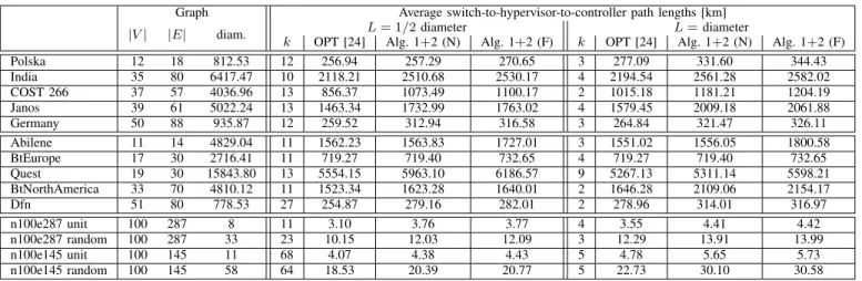
In this section we compare our approach to an optimal hypervisor placement method which finds a given number ofk hypervisor locations which minimize the average control path lengths for a pre-defined set of static virtual network requests, without any resilience requirement [24]. Our simulation results are presented in Table II for several SNDLib [40] and Internet Topology Zoo [44] topologies. Note that, in order to obtain real physical distances of the nodes we removed locations without coordinates from the data set, as well as did not consider 1-degree nodes because of the resilience perspective (please, refer to Appendix B for further details). Thus, Table II contains the properties of the resulting topologies.
As the ILP in [24] (and other traditional HPP algo- rithms [25], too) has completely different objective function and inputs as our self-driving problem definition in the dy- namically changing environment, we conducted the following procedure to obtain comparable results of the two approaches:
TABLE II
AVERAGE CONTROL PATH LENGTHS(UPPER PART: SNDLIB[40],MIDDLE PART: INTERNETTOPOLOGYZOO[44],LOWER PART:SYNTHETIC PLANAR TOPOLOGIES GENERATED WITHLEMON [41]).
Graph Average switch-to-hypervisor-to-controller path lengths [km]
|V| |E| diam. L= 1/2diameter L=diameter
k OPT [24] Alg. 1+2 (N) Alg. 1+2 (F) k OPT [24] Alg. 1+2 (N) Alg. 1+2 (F)
Polska 12 18 812.53 12 256.94 257.29 270.65 3 277.09 331.60 344.43
India 35 80 6417.47 10 2118.21 2510.68 2530.17 4 2194.54 2561.28 2582.02
COST 266 37 57 4036.96 13 856.37 1073.49 1100.17 2 1015.18 1181.21 1204.19
Janos 39 61 5022.24 13 1463.34 1732.99 1763.02 4 1579.45 2009.18 2061.88
Germany 50 88 935.87 12 259.52 312.94 316.58 3 264.84 321.47 326.11
Abilene 11 14 4829.04 11 1562.23 1563.83 1727.01 3 1551.02 1556.05 1800.58
BtEurope 17 30 2716.41 11 719.27 719.40 732.65 4 719.27 719.40 732.65
Quest 19 30 15843.80 13 5554.15 5963.10 6186.57 9 5267.13 5311.14 5598.21
BtNorthAmerica 33 70 4810.12 11 1523.34 1623.28 1640.01 2 1646.28 2109.06 2154.17
Dfn 51 80 778.53 27 254.87 279.16 282.01 2 278.96 314.01 316.97
n100e287 unit 100 287 8 11 3.10 3.76 3.77 4 3.55 4.41 4.42
n100e287 random 100 287 33 23 10.15 12.03 12.09 3 12.29 13.91 13.99
n100e145 unit 100 145 11 68 4.07 4.38 4.43 5 4.78 5.65 5.73
n100e145 random 100 145 58 64 18.53 20.39 20.77 5 22.73 30.10 30.58
• Find a hypervisor placement inG(V, E)with Alg. 1 for a given maximum distance L. As an output it gives us the knumber of hypervisors (and their locations).
• Generate 100 virtual network requestsR1, . . .R100with each containing 2 to 10 random virtual switches and find controller locationsc1, . . . c100based on total control distance D according to Section V-A. We decreased the number of request from 1000 to avoid memory constraints of the ILP [24].
• Calculate the average length of all control paths in all requests along the pre-allocated resilient path-pair with Alg. 2 without link failures and the increased control path lengths upon all single link failures (columns Alg. 1+2 (N) and Alg. 1+2 (F) in Table II, respectively).
• Define the input parameters of the ILP [24] as topology G(V, E), hypervisor number k, and virtual network re- quests {Ri, ci}, i= 1, . . .100. For our use case we have implemented the ILP in [24] with the average latency objective function and without the multi-controller switch constraints. Therefore, the solution of the ILP gives the optimal hypervisor locations for the given set of requests and the optimal average switch-to-hypervisor-to- controller path lengths, denoted as OPT [24] in Table II.
The diameter and the half of the diameter of the topologies were considered as maximum switch-to-hypervisor distances Lin Table II in order to produce significantly different number of hypervisors k. However, in this setting if the L = 1/2 diameter is considered, the SLA violations are above 50%
owing to the shorter allowed control distances. For this tighter constraint with more hypervisor instances and more partitions one would expect decreased control path lengths, which can be observed in most topologies. However, in some Internet Topology Zoo [44] networks one can observe that the more locations result in the same or even increased average control path lengths. First, in case of the BtEurope topology the path lengths are exactly the same for both distance constraints, because there is a central node with high betweenness value which acts as the hypervisor location for most physical switches. Furthermore, our algorithm in Section V-A places the
controller to this node for almost every virtual network request.
Therefore, increasing the number of hypervisor instances has no additional benefit. Second, more hypervisor instances can cause increased average control path length as well which is counter-intuitive. However, note that owing to the resilience requirement we selected the controller location in each virtual network based on total control distance D from the involved hypervisor instances and not on average control path length.
Hence, in topologies like Abilene or Quest where a detour path could be extremely long, this resilient controller placement metric performs poor in terms of average control path length for specific virtual network requests.
We conducted simulations on synthetic 100-node planar topologies generated with LEMON [41] to investigate the effect of the network density and varying link lengths on the performance in Table II, and to analyze the running time on larger topologies. Our observation is that with large number of hypervisors the gap between the optimal average control path length and our resilient average control path length is larger in denser topologies, while with a few hypervisor locations link lengths have higher influence on the perfor- mance. Furthermore, the running time for the unit case (i.e.,
∀e ∈ E : l(e) = 1) is lower for both algorithms than the uniformly random link lengths, i.e., in the 287-link network it is 8.45 s compared to 9.35 s for Alg. 1+2, and 150.94 s compared to 375.42 s for OPT [24], measured on a machine running Debian Linux version 4.9, with four 2.59 GHz Intel processors and with 8 GB RAM.
The difference between OPT [24] calculated with the knowledge of all virtual network requests and without any resilience requirement, and our resilient Alg. 1+2 without any a priori knowledge of the requests varies significantly in different topologies. In smaller sparse networks where the number of options is limited the difference is negligible and our approach provides instantaneous single link failure recovery for the optimal placement. However, as the size and density of the network increase, the price we pay for resilience and for supporting dynamic behaviour can be up to 20-25% increased average control path length depending