ГК n 'S k O
KFKI-1982-71
A , G O S S Ä N Y I 1 T . P Á R K Á N Y I
\
G, S Z A B Ó E. VEGHERROR DIAGNOSTICS AND RECOVERY PROCEDURE IN A DUAL-PROCESSOR COMPUTER SYSTEM
'Hungarian Academy o f Sciences
CENTRAL RESEARCH
INSTITUTE FOR PHYSICS
BUDAPEST
2017
ERROR D I A GNOSTICS AND RECOVERY PROCEDURE IN A DUAL- P R O C E S S O R COMPUTER SYSTEM
A. GOSSÄNYI, T. PÁRKÁNYI, G. SZABÓ and E. VÉGH Central Research Institute for Physics H-1525 Budapest 114, P.O.B. 49, Hungary
HU ISSN 0368 5330 ISBN 963 371 957 7
KFKI-1982-71
ABSTRACT
Reliability is one of the most important problems of industrial process control computers. This report describes the error protection method used in the computerized control system of the 5 MW research reactor of the Central Research Institute for Physics. The computer system consists of two R-10 pro
cessors; at a given time only one of them is executing the control of the re
actor. The used on-line error diagnostic algorithms and the error recovery procedures are presented in this paper.
АННОТАЦИЯ
©
Одна из самых важных проблем создания промышленных управляющих вычисли
тельных систем - обеспечение необходимой надежности. Статья описывает систе
му защиты от отказов управляющей вычислительной машины исследовательского ядерного реактора ЦИФИ с мощностью 5 МВт. Система управления состоит из двух ЭВМ типа Р-10, из которых только одна ведет активное управление ядерным ре
актором. Описаны "он-лайн" алгоритмы диагностики отказов, а также стратегии усреднения ошибок.
KIVONAT
Ipari folyamatirányitó számitógépek egyik legfontosabb problémáját a meg felelő megbizhatóság biztosítása képezi. A cikk ismerteti a Központi Fizikai Kutató Intézet 5 MW-os kutató reaktorához kidolgozott számitógépes irányitó rendszer hibavédelmi módszerét. A számítógéprendszer két R-10 processzorból áll, amelyek közül mindig egy végzi a tényleges reaktorirányitást. A cikk is
merteti az alkalmazott on-line hibafelismerési algoritmusokat, valamint vázol ja a hibaelháritási stratégiát.
INTRODUCTION
Error diagnostics and recovery procedures present maybe the most delicate and interesting problems in a high reliability dual processor computer system. The system designer faces the follow
ing problem: if he creates a system which detects all of its mal
functions, this system has absolutely no value, because it has no time to do anything else but to check its correct operation.
Naturally, the designer has no wish to produce an electronic Buddha meditating on his navel but, rather, a process control sys tern with high reliability. In view of this he has to find a com
promise between the overheads of the diagnostic programs and the remaining error probability of the system.
An industrial process control computer is a highly complex electronic system in spite of which its malfunctions can be clas
sified into just two categories: correctable errors and catastro
phic errors. An error is correctable if the erroneous component can be replaced by some type of redundant element without any no
ticeable degradation in the operation of the system: e.g. if a measuring channel goes wrong, it can be detected by validity
checking and a redundant measurement initiated.
If a catastrophic error occurs, the entire computer system is unable to operate properly so a standby computer must be start ed in order to maintain the basic functions of the system. Very often there is some type of system degradation in this case.
This paper deals only with catastrophic error diagnostics and error recovery procedure.
2
CONFIGURATION
The process control computer configuration is shown in Fig.
1. It consists of two R-IO computers (32 Kwords, floating point processor) and two fixed head disc units each with 800 kbytes ca
pacity. The peripheral system and the real-time measuring subsys
tem are connected to the measuring computer by an electronic switch, operated by the coordinator unit. This unit supervises the operation of the measuring computer and that of the standby processor. The standby processor is not idle, it provides differ
ent data analyses on the measured and processed information (e.g.
trend analysis). The two processors are connected to each other by a direct memory access (DMA) line. In both computers the
PROCESS industrial control software system operates [1]. This sys
tem provides a stand-alone monitor and a utility program library with which the user can describe his control problems in PROCESS language and he can compile, load,debug and modify his programs in the background without disturbing the operation of the already loaded user programs.
ERROR SI GNALIZATION
Error diagnosis means two different things:
- error signalization, - error localization.
Error signalization simply detects that a catastrophic error has developed in the system and the real-time tasks have to be executed in the standby processor. In the described dual R-10 system it is controlled by a simple watch-dog timer. This timer produces an operable signal to the coordinator unit until it re
ceives a pulse generated at the end of the on-line test programs every 0.5 sec. When the operable signal disappears because of er
ror, the coordinator switches the peripherals and the real-time subsystem to the other processor and the standby system is ac
tivated. Here it is important that the error free operation is signalized by a pulse train instead of a signal level, because dynamic signalization (pulse train) is much more resistant to
3
error than static signalization (static signal levels). For ex
ample, a simple short circuit can produce false operation in the case of static signalization whereas an erroneous system can main
tain a pulse train with precise timing in the case of a very sophisticated (thus very improbable) error.
The correct operation of the hardware environment is checked at three levels
- in the hardware, - in the microprogram, - in the program itself.
In all cases, if a test finds an irregularity, an error code is written into the error register, thereby causing program sus
pension with highest priority at the microprogram level, (see Fig. 2).
This suspension
- stops the running of the CPU (in this way the pulse train of the operable signalization disappears)
- initiates a special microprogram (which loads the sys
tem loader from the disc).
We use here suspension instead of program interruption be
cause the former cannot be masked out.
The test system checks the following components:
- memory,
- central processor,
- floating point processor, - disc unit,
- DMA connection, - real-time bus.
Each of these components has its on-line test executed simul
taneously with the real-time tasks. Every test has access to one bit in the error register (see Fig. 3). When anything is stored
in the error register the CPU gets a clear pulse (RAZ) and the loader microprogram is initiated.
The DMA connection is checked only on the standby processor and if it goes wrong the standby processor signalizes a DMA error even if it is actually the other end of the connection that is erroneous.
The CPU and the floating point processor are checked by two on-line test programs every 0.5 seconds. The CPU test checks the
4
executing part of the R-IO processor using the following sequence:
- test of the program indicators, compare and jumping, - test of the addressing modes,
- test of memory reference instructions, - test of the arithmetic instructions, - test of the logical instructions, - test of the shift instructions,
- test of register-register instructions, - test of the string instructions.
The overhead of the CPU test is about 0.1 %. The floating point processor is checked by a randomly selected normalized num
ber with which all of the floating arithmetic instructions are performed in such a sequence that the resulting number should be the initial value. The error must be less than 3 bits in the man
tissa. The overhead of this test is 0.04 %.
The real-time bus is checked only in the measuring processor.
Every second this test sends a randomly selected pattern to a digital output connected to a given digital input. The test checks if the pattern received and the pattern sent are the same. The overhead of this test is 0.01 %.
The memory is tested by a special microprogram which writes a pattern into the selected memory location then reads it back and checks if it is the same as the original word. The program checks the whole memory in 2.5 seconds, with one pattern. A total of 36 different patterns is used, so the whole memory is tested in 1.5 minutes. The microprogram is executed every 80 usee and its running time is 4.8 usee so the overhead of memory testing in 6 %.
The disc unit is tested by a special time-out counter. This unit measures the data transfer time of the disc and sets the corresponding bit of the error register if it is too long. The time-out counter is used by the disc handler of the PROCESS oper
ating system. This type of checking causes practically no over
head.
5
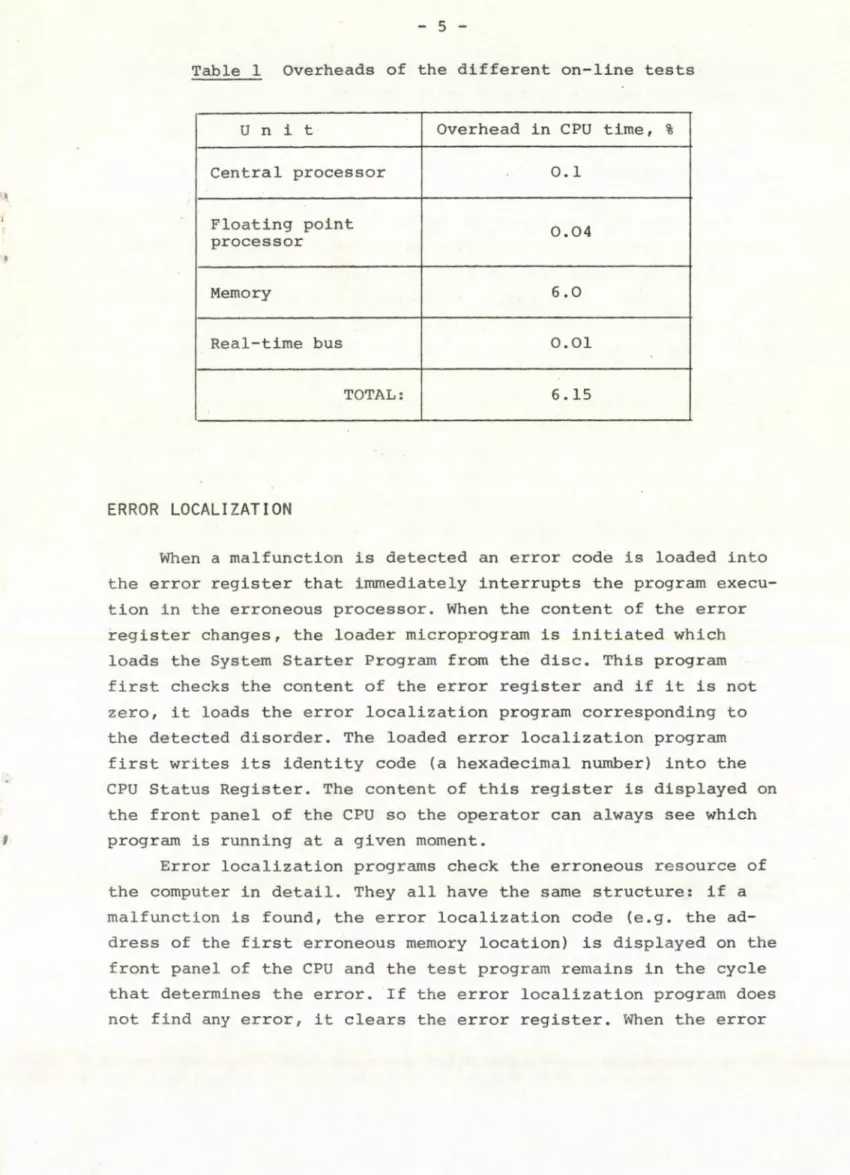
Table 1 Overheads of the different on-line tests
U n i t Overhead in CPU time, %
Central processor 0.1
Floating point
processor 0.04
Memory 6.0
Real-time bus 0.01
TOTAL: 6.15
ERROR LOCALIZATION
When a malfunction is detected an error code is loaded into the error register that immediately interrupts the program execu
tion in the erroneous processor. When the content of the error register changes, the loader microprogram is initiated which loads the System Starter Program from the disc. This program first checks the content of the error register and if it is not zero, it loads the error localization program corresponding to the detected disorder. The loaded error localization program first writes its identity code (a hexadecimal number) into the CPU Status Register. The content of this register is displayed on the front panel of the CPU so the operator can always see which program is running at a given moment.
Error localization programs check the erroneous resource of the computer in detail. They all have the same structure: if a malfunction is found, the error localization code (e.g. the ad
dress of the first erroneous memory location) is displayed on the front panel of the CPU and the test program remains in the cycle that determines the error. If the error localization program does not find any error, it clears the error register. When the error
6
register is cleared, the loader microprogram is again initiated in order to load the System Starter Program.
RECOVERY PROCEDURE
The main program types in one processor of the dual R-10 sys
tem can be seen in Fig. 4. During Initial Program Loading (IPL) the Loader Program is called from the disc which loads the System Starter Program. This program first reads the content of the er
ror register; if it is not zero the error localization program determined by the error code is initiated. The error localization program remains in a cycle pointing to the error if it finds a disorder, otherwise it clears the error register and the Loader Program is started again.
When the Starter Program finds zero in the error register it checks the hardware environment and if there is no error it starts the Process Control Program. This program system contains the on- -line test system described previously. If any of the test pro
grams determines on irregularity it loads the error code into the error register, thereby causing the suspension of the program, then the Loader Program is called again. The test programs of the CPU and floating point arithmetic unit are executed every 0.5 sec;
at their successful end a pulse is sent toward the coordinator unit as operating signalization.
Any of the processors and disc units may be switched off for repair at any time, and the other configuration continues the execution of the real-time tasks without interruption. After re
pair the unit can be initiated by the Initial Program Loading and the dual system operates with full power automatically.
REFERENCE
[1] L. Bürger, E. Végh et al.: PROCESS-24K - an efficient process control system, Report KFKI-1978-17
DMA
I I
Fig- 1
Hardware configuration
Fig. 2
Hardware and software parts of the error diagnostic system
9
0
CPU error
ltoal-tiino bus error DMA lino error_____
Floating processor error
Hoinoi-y error Disc unit err.
Fig. 3
Structure of the error register
Fig. 4
Main program components
A
4
т
<
Kiadja a Központi Fizikai Kutató Intézet Felelős kiadó: Gyimesi Zoltán
Szakmai lektor: Bürger Gáborné Nyelvi lektor: Harvey Shenker Gépelte: Polgár Julianna
Példányszám: 395 Törzsszám: 82-470 Készült a KFKI sokszorosító üzemében Felelős vezető: Nagy Károly
Budapest, 1982. szeptember hó