PRELIMINARY ANALYSIS OF AN RC
CONTAINMENT STRUCTURE SUBJECTED TO AIRCRAFT-IMPACT
Lili Eszter Hlavicka-Laczák – György Farkas
Analysis of aircraft impact is required for newly designed nuclear power plant containments, that are typically robust reinforced concrete (RC) or prestressed concrete structures. In our paper we shortly summarize the main function of containments and show some typical examples for their structural arrangement. From the point of view of the impact we show the typical effects of an aircraft impact and the analysis methods of it. In the second part of the paper a preliminary analysis for aircraft impact into a prestressed concrete containment building is executed with different methods and with a military jet and a large passenger aircraft. At the end results of the analysis are evaluated and suggestions for more detailed modelling are made.
Keywords: nuclear power plant containment, prestressed concrete, aircraft impact
1. INTRODUCTION
The probability of an aircraft impact into conventional engineering structures is extremely low, therefore it is not included in the design standard. However, in case of nuclear power plants (NPPs) or other nuclear related facilities, because of the severe consequences (e.g. release of radioactive substances), aircraft impacts have to be analysed. Beside the safety of operating NPPs it is also important regarding the design of new ones. According to the Hungarian regulations (Government Decree 118/2011) impact of smaller military jets and also of larger civil aircrafts has to be analysed.
In this paper we shortly summarize the functions and arrangement of NPP containment buildings and the effects of an aircraft impact into them. We also present the possible modelling techniques of reinforced concrete and prestressed concrete structures subjected to impact loading.
In the second part of the paper a preliminary analysis is presented where both impact of a military jet and of a larger
commercial aircraft is examined into a prestressed concrete containment building. After the analysis the results are evaluated, and suggestions are made for further researches.
2. CONTAINMENT STUCTURES OF NUCLEAR POWER PLANTS
2.1 Functions and arrangement of containment structures
The containment (hermetic protective building) is the structure that surrounds the reactor and the systems directly connected to it. From the structural point of view, it is a pressure vessel that should retain the overpressure that occurs in case of accidents. It also means the final physical barrier between equipment of the nuclear technology and the environment. This barrier function includes the protection of
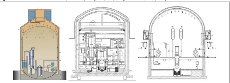
Fig 1: Schematic cross-section of AP 1000 (Sahlin et al., 2015), EPR (Areva, 2007), VVER-1200 (Aszódi, 2017)
DOI: 10.32970/CS.2019.1.2
the environment from fission products and ionising radiation and the protection of the internal technology from external natural hazards and human activities (meteorological loads, explosion, fire, aircraft-impact etc.) as well.
Based on the Nuclear Safety Code Vol. 3a 4.6. (Annex 3/A to Government Decree No. 118/2011 (VII.11.)) the containment function can be provided by either one or two separate containment structures. In the latter case, subatmospheric pressure in the space between the two structures should be kept, in order to detect leakage through the inner wall and to prevent the release of radioactive substances into the environment. In case of double-walled containments the protective function is separated: the inner (primary) containment has to be designed for overpressure (that occurs in case of a LB LOCA=large break, loss of coolant accident), while the outer (secondary) for aircraft impact.
The inner containment can be a steel vessel with a concrete external shield building (e.g. AP1000, where the inner steel wall is 4.5 cm thick, the outer concrete wall is ~0.9 m with 2 cm thick steel plating (Sahlin et al, 2015)). Instead of a steel inner wall it is also typical to use prestressed concrete, two examples for this are the EPR (European Pressurized Reactor, inner containment: 1.3 m thick post-tensioned concrete with 6 mm metallic liner, outer shield building: 1.3-1.8 m thick reinforced concrete (Areva, 2007)) and the VVER-1200 (inner wall 1.2 m post-tensioned concrete; outer wall: 0.5 m thick reinforced concrete (Asmolov et al., 2017)), see Fig. 1.
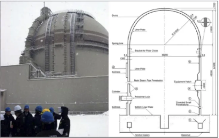
In case of single-wall containments both protective functions are provided by the same wall, this solution is typical for the NPPs operating since the 70’s-90’s (Generation II), that were not designed for aircraft-impact. One example is the Unit 3 of Ohi NPP in Japan (see Fig. 2), where 1.1-1.3 m thick
post-tensioned concrete wall is applied. Another example is the Paks 1 NPP (Fig. 3), where VVER-400 reactors operate, in this case a bubble condenser containment building is built, which means a hermetic compartment system in which the steam-air mixture generated within a LB LOCA is transferred into the bubble condenser system where it is condensed and the pressure is reduced (Blinkov et al., 2012).
2.2 Design requirements for aircraft impact
Based on the Annex 3/A to Government Decree No. 118/2011 for new NPPs crash of a military or civilian aircraft is included in the design basis, which means that the criteria of design basis (TA) operating conditions have to be met in case of aircraft crash that has higher probability than 10-7/year (that is the frequency limit for external hazard factors associated with human activities). Selection of the aircraft types that have to be analysed is done by taking into account the statistics of accidents and the location of airports near the site of the NPP.
Crash of a military or civilian aircraft is also included in the extension of the design basis: requirements for TAK1 (complex accident) operating condition should be fulfilled.
For any possible military or civil aircraft it has to be proved that: a) the cooling of the active core of the nuclear reactor is not compromised or b) the containment is not damaged, and c) the cooling or integrity of the spent fuel pool is maintained.
In this case large passenger planes are the critical missiles that have to be examined without analysing the probability of their impact.
3. EFFECTS OF AIRCRAFT IMPACT AND THEIR ANALYSIS
The effects of an aircraft impact into a relatively rigid structure depend on multiple factors. The most important parameters are the size, mass, stiffness of the aircraft, direction and location of the impact and properties of the target structure (containment). The effect of different parameters was analysed in details by Laczák (2017). We can distinguish between two primary effects: global and local effects. The first means the overall structural response of the target structure, while the second means the effects that locally cause significant damages at the impact zone (Fig. 4). Beside primary effects, secondary effects such as vibrations, fire, explosion, high temperatures can also be significant. In this paper we mainly focus on global primary effects.
Fig 3: Cross-section of the hermetic compartment system of Paks 1 (without the reactor hall building), (Boros, 2017)
Fig 2: Ohi NPP, Unit 3 from outside (source: wikipedia.org- Ohi Nuclear Power Plant) and schematic cross-section of the containment (Sandia National Laboratories, 2003)
Fig 4: Local effects: (a) penetration, (b) cone cracking, (c) spalling, (d) cracks, (e) scabbing, (f) perforation and global effect (g) of missile impact (Li et al., 2005)
The damage caused by the aircraft or its parts to a great extent depends on the stiffness and rigidity of the missile and the target. Usually, an aircraft fuselage that impacts a concrete structure with thick walls means a deformable (soft) missile causing global effects while the engine behaves as a non-deformable (hard) missile that causes local effects (penetration, perforation, scabbing). A detailed full-scale test series was done by Sugano et al. using a Phantom F4 fighter (Fig. 5) and its engine (Sugano et al., 1993-1,2,3). In general, different models and methods are used for the analysis of global or local effects, we will discuss them shortly in the following.
3.1 Global effects
Global effects are mainly caused by deformable missiles, such as the fuselage of an aircraft if the impact velocity is sufficiently high and the target is sufficiently rigid. In this
Fig.5: Full-scale impact test of a Phantom F4 fighter (Sugano et al., 1993-1)
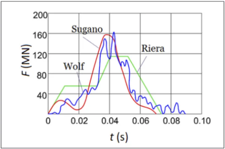
case the impact can be substituted by a load-time function acting on the target. Such load-time functions are prescribed by the standards (Katona, 2015) or can be determined by different analytic methods, from which the most frequently used is the Riera method (Riera, 1968). Both the method of Riera and the lumped-mass model of Wolf (1978) have been verified during the experiment of Sugano et al. (1993-1), as the calculated load-time function approximated well the measured impact force-time function acting on a rigid wall during the test shown in Fig. 5. The calculated and measured load-time functions are presented in Fig. 6.
As the available computational capacity increases, application of detailed numerical models that includes both the aircraft and the containment becomes possible, this analysis type is called missile-target interaction method. On the one hand these models can provide detailed information on the behaviour of the structure and of the missile. On the other hand, several parameters appear in these advanced models, which can lead to uncertainties, therefore the application of load-time functions for calibration of detailed models is still relevant. For preliminary analysis it is also suggested to use a linear elastic target by assuming that the effects of nonlinearity are only important in the vicinity of the impact zone. Two examples for detailed numerical models for the analysis of global effects are shown in Fig. 7. Both use volume elements with concrete material model and the reinforcement is modelled by constrained line elements.
3.2. Local effects
The local effects are typically dominant when the deformations of the missile are negligible compared to the damages of the target. Local damages are material specific, the most important effects in case of RC structures are shown in Fig. 4. From the point of view of the barrier function of the containment building the most important parameters are the required thicknesses to prevent perforation or scabbing.
In case of scabbing the missile does not perforate the target, but the formation of debris (secondary missiles) can also cause damage in the protected zone. The determination of the required thicknesses is done by analytic, semi-empirical and numerical calculation methods. Summarizing articles on local failure calculations were published by Kennedy (1976), Teland (1998), Li et al. (2005) and Murthy et al. (2010).
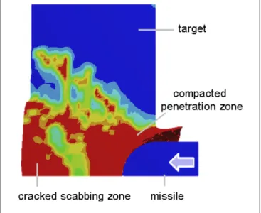
An example for numerical tests is shown in Fig. 8 where a quarter model of a wall is shown for a rigid bullet impact. The applied material model is an advanced explicit material model for concrete, that can follow the local damages (compaction, penetration, scabbing). Red colour represents the totally damaged elements, while blue colour shows the intact parts.
Fig 7 left: Model of the impact of a Boeing 747 into a fictious containment building (Arros, 2007); right: model of an RC containment and the damage after impact of a Phantom F4 (Iqbal et al., 2012)
Fig 6: Load-time function in case of impact of a Phantom F4 fighter with 215 m/s, (based on Riera (1968), Wolf (1978) and Sugano et al.
(1993-1))
4. PRELIMINARY ANALYSIS OF A CONTAINMENT STRUCTURE
As a case study, preliminary analysis of a containment with simplified geometry and prestressing of the Unit 3 of the Ohi NPP is done for the impact of a Phantom F4 and of a Boeing 747 aircraft, the impact velocity is 215 m/s in both cases. The containment building was chosen because it was examined in details during a 1:4 scale overpressurization test (Sandia National Laboratories, 2003), therefore details of its pre- stressing system are available. The mentioned aircraft types were chosen because they are frequently used in the related literature.
4.1 Numerical model
The finite element (FE) model is built in Ansys Workbench Explicit Dynamics environment. The model of the containment building consists of a cylindrical building with hemispherical dome. Linear elastic volume elements are used (Young’s modulus 35 GPa, Poisson ratio 0.2, density 2500 kg/m3), the reinforcement is not modelled. The wall thickness is 1.2 m, the height of the cylinder is 43.0 m, total height of the structure is 65.7 m, outer radius of the cylinder and of the hemisphere is 22.7 m, average element size is ~1m (Fig. 9). We do not take into account that Young’s modulus of concrete depends on the loading rate. The design overpressure of the Unit 3, Ohi NPP containment is 0.47 MPa, therefore its prestressing system was designed to provide decompression in case of such overpressure. In the model, effect of prestressing is taken into account by -0.47 MPa negative internal pressure, that points towards the interior and acts in the normal direction of the internal surface of the cylinder and of the hemisphere. The calculation is done in two steps: at first, static analysis is done with application of the prestressing, then in the second step the results of the static calculation are used as initial conditions for the explicit dynamic analysis. In case of the Phantom F4 both a load- time function and a missile-target interaction model are used, while for the Boeing 747, only a load-time function is applied. Normal directional impact at the connection of the cylinder and the hemisphere are investigated (see Fig. 9 left).
In case of the load-time function the load is distributed on a
Fig 8: Damage of a concrete target in case of impact of a rigid missile, red colour represents the totally damaged elements, blue colour shows the intact parts (Laczák and Károlyi, 2016)
circular surface with 3 m diameter.
4.2 Analysis of military jet impact
Impact of a Phantom F4 fighter is examined at first. The load- time function is a simplified function determined by the Riera method. For the missile-target interaction model a simplified aircraft geometry is used with bilinear kinematic hardening material (initial Young’s modulus 200 GPa, hardening modulus 2 GPa, Poisson ratio 0.3, limit stress 30 MPa, density 5500 kg/m3), the finite elements of the aircraft fail and are deleted from the model if limit compressive strain value 1.0 is reached. Length of the aircraft is 17.5 m, its mass is 4655 kg+2626 kg+12208 kg=19.5 tonnes (wings + engines + fuselage). Wall thickness in the model is 2.5 cm for the fuselage and wings, 10 cm for the engines, average FE size is 0.2-0.4 m.
Fig. 10 shows the load that acts on the containment wall, which is the load-time function in one case and the measured contact force-time function in case of the missile-target interaction. Difference between the two can be explained by the difference in the engines’ stiffness in the FE model and in the model with load-time function. By more detailed modelling of the engines the difference can be reduced.
Crushing of the model aircraft is shown in Fig. 11.
Fig. 12 shows the horizontal displacement of the containment as a function of time at the middle point of the impact zone. The shape of the displacement-time functions follows the shape of the force-time functions, maximum displacements from the linear elastic model are 0.028 m (missile-target interaction method) and 0.036 m (load-time function). Global structural behaviour of the containment in case of the load-time function can be followed in Fig. 13, where horizontal displacement of the top of the dome (at
Fig 9: Geometry of the containment and the Phantom F4, and FE mesh of the containment
Fig 10: Load that acts on the containment in case of missile-target interaction method and in case of application of the load-time function
height h=65 m), horizontal displacement at the middle of the impact zone (at height h=43 m (max)) and at the height of the impact but at the point farthest from the impact (on the other side of the building, at height h=43 m (min)) are shown. It is visible that the cantilever-like horizontal deformation of the building is small (the top of the containment moves only 0.01 m) compared to the local displacement in the impact zone. The maximum (linear elastic) tensile stress also arises at the impact zone, it is 26.2 MPa in case of the missile-target method and 37.7 MPa in case of the load-time function, the magnitude of the tensile stress shows that crack formation and nonlinear behaviour should be considered in the impact zone. This magnitude of stress shows that detailed analysis is needed with nonlinear and concrete specific material models as such tensile stresses cannot occur in concrete.
Fig 11: Crushing of the model aircraft (time is given in seconds)
Fig 12: Horizontal displacement of the containment at the impact zone in case of missile-target method and in case of application of the load-time function
Fig 13: Maximum horizontal displacement of the containment at different height in case of application of the load-time function (Phantom F4)
4.3 Analysis of passenger aircraft impact
Impact of a Boeing 747 passenger aircraft is analysed by a simplified load-time function determined by the Riera method.
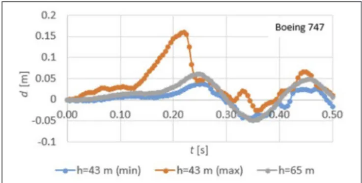
It is represented in Fig. 14, together with the functions used and measured by Arros (2007). Maximum displacements are presented in Fig. 15, results belong to the same points as in Fig. 13 (top of containment, at the height of the impact at the impact zone and at the point farthest from the impact zone).
We can see that the maximum displacement at the impact zone is ~0.16 m and the cantilever-like displacement of the building becomes significant (0.06 m at the top and 0.04 cm at the height of the impact). The maximum tensile stress is 58 MPa in the impact zone, but at the bottom of the cylinder, because of the cantilever-like global behaviour 50 MPa tensile stress also arises, therefore in this case crack formation and nonlinear-behaviour should be considered not only at the impact zone but also at the zone close to the support.
5. CONCLUSIONS
In our paper preliminary analysis for aircraft impact into a prestressed concrete containment building was executed, effect of prestress was taken into account by initial conditions of the dynamic analysis. Both missile-target interaction analysis and load-time function method were applied and impact of a Phantom F4 military jet and a Boeing 747 passenger aircraft was examined. Impact of the Phantom F4 caused significant deformations and stresses around the impact zone, where the maximum horizontal displacement was 0.03-0.04 m. In case of the impact of the Boeing 747 aircraft, the maximum displacement was ~0.16 m and global cantilever-like motion of the building was also significant.
The analysis showed that application of nonlinear material models and detailed structural modelling are needed around
Fig 15: Maximum horizontal displacement of the containment at different height in case of application of the load-time function (Boeing 747)
Fig 14: Load-time functions for impact of a Boeing 747 with 215 m/s
the impact zone and in case of the Boeing 747 also around the supports, because these are the critical zones where crack formation and nonlinear material behaviour (yielding of steel bars, softening of tensioned concrete, plastic deformations etc.) occur. The results of such preliminary analysis are useful for approximation of the effects and to show the further required steps and level of detailed modelling.
6. ACKNOWLEDGEMENT
The research reported in this paper was supported by the Higher Education Excellence Program of the Ministry of Human Capacities in the frame of the Water sciences &
Disaster Prevention research area of the Budapest University of Technology and Economics (BME FIKP-VÍZ).
7. REFERENCES
Annex 3/A to Government Decree No. 118/2011 (VII.11.) http://www.oah.hu/web/v3/HAEAportal.nsf/05F9A474178B5B 8CC1257E370029DCE1/$FILE/NSC_3a_en.pdf
Areva (2007), „UK EPR. Fundamental Safety Overview, Vol. 1:
Head Document, Chapter A: EPR Design Description”
Arros J. (2007), „Analysis of aircraft impact to concrete structures.”
Nuclear Engineering and Design 237, pp. 1241-1249. https://doi.
org/10.1016/j.nucengdes.2006.09.044
Asmolov, V. G., Gusev, I. N., Kazanskiy, V. R., Povarov, V. P., Statsurab, D.B. (2017), „New generation first-of-the kind unit – VVER-1200 design features”, Nuclear Energy and Technology 3 (4), pp. 260-269. https://doi.org/10.1016/j.nucet.2017.10.003 Aszódi A. (2017), „Technical and safety analysis of nuclear power
technology.” website of Paks 2 NPP. http://www.paks2.hu/en/
news/SitePages/newsDetails.aspx?NewsID=241
Aszódi A. (2007), „Why the VVER-1200 techology was chosen by Hungary during the realization of Project Pak II?” (in Hungarian) https://aszodiattila.blog.hu/2017/09/25/miert_a_vver-1200_
technologiat_valasztotta_magyarorszag_a_paks_ii_projekt_
megvalositasakor
Blinkov, V. N, Melikhov, O. I., Melikhov, V. I.,Davydov, M. V., Wolff, H. and Arndt S. (2012) „Experimental Studies for the VVER-440/213 Bubble Condenser System for Kola NPP at the Integral Test Facility BC V-213” Science and Technology of Nuclear Installations Vol. 2012. Article ID 275693. http://dx.doi.
org/10.1155/2012/275693
Boros I. (2017), slide of presentation of the subject „Technologies in nuclear power plants- Containment” (in Hungarian), Institution of Nuclear Techniques, Budapest University of Technology and Economics. http://oldweb.reak.bme.hu/fileadmin/user_upload/
felhasznalok/boris/AE_Technologiak_VIK/2017_05_AE_
Technologiak_BI_kiadott.pdf
Government Decree 118/2011 (2011): https://net.jogtar.hu/
jogszabaly?docid=A1100118.KOR
Iqbal, M. A., Rai, S., Sadique, M. R., Bhargava, (2012) „Numerical simulation of aircraft crash on nuclear containment structure.”
Nuclear Engineering and Design. 243, pp. 321-335. https://doi.
org/10.1016/j.nucengdes.2011.11.019
Katona, T. (2015), „Design of systems of high significance and their elements. The containment and its systems. Constructional arrangement of the containment and its structural integrity” (in Hungarian) http://oldweb.reak.bme.hu/fileadmin/user_upload/
felhasznalok/karolyi/kontenment.pdf
Kennedy, P. (1976), “A review of procedures for the analysis and design of concrete structures to resist missile impact effects.”
Nuclear Engineering and Design 37, pp. 183-203. https://doi.
org/10.1016/0029-5493(76)90015-7
Laczák, L.E. (2017) “Evaluation of important parameters of aircraft impact into relatively rigid engineering structures.” PhD dissertation, Budapest University of Technology and Economics.
Laczák, L.E. and Gy. Károlyi (2016) “Local Effects of Impact into Concrete Structure.” Periodyca Polytechnica Civil Engineering 60, pp. 573-582. https://doi.org/10.3311/PPci.8605
Li, Q. M., Reid, S. R., Wen, H. M., Telford, A. R. (2005) “Local impact effects of hard missiles on concrete targets.” International Journal of Impact Engineering 32, pp. 224-284. https://doi.
org/10.1016/j.ijimpeng.2005.04.005
Murthy, A.R.C., Palani, G. S., Iyer, N. R. (2010) ”Impact analysis of concrete structural components.” Defense Science Journal 60, pp. 307-319. https://doi.org/10.14429/dsj.60.358
Riera, J. D. (1968), „On the stress analysis of structures subjected to aircraft impact forces.” Nuclear Engineering and Design 8, pp.
415-426. https://doi.org/10.1016/0029-5493(68)90039-3 Sahlin et al.: Evaluating the impact of climate change on the risk
assessment of Nuclear Power Plants, Safety and Reliability of Complex Engineered Systems – Podofillini et al. (Eds) © 2015 Taylor & Francis Group, London, ISBN 978-1-138-02879- 1. https://www.researchgate.net/publication/282504897_
Evaluating_the_impact_of_climate_change_on_the_risk_
assessment_of_Nuclear_Power_Plants/figures?lo=1
Sandia National Laboratories (2003) „Overpressurization Test of a 1:4-Scale Prestressed Concrete Containment Vessel Model.”
NUREG/CR-6810, SAND2003-0840P, https://www.nrc.gov/
docs/ML0320/ML032040014.pdf
Sugano, T., Tsubota, H., Kasai, Y., Koshika, N., Orui, S., von Riesemann, W. A., Bickel, D. C., Parks, M. B. (1993-1) „Full- scale aircraft impact test for evaluation of impact force.”
Nuclear Engineering and Design 140, pp. 373-385. https://doi.
org/10.1016/0029-5493(93)90119-T
Sugano, T., Tsubota, H., Kasai, Y., Koshika, N., Ohnuma, H., von Riesemann, W. A., Bickel, D. C., Parks, M. B. (1993-2) „Local damage to reinforced concrete structures caused by impact of aircraft engine missiles Part 1. Test program, method and results.”
Nuclear Engineering and Design 140, pp. 387-405. https://doi.
org/10.1016/0029-5493(93)90120-X
Sugano, T., Tsubota, H., Kasai, Y., Koshika, N., Ohnuma, H., von Riesemann, W. A., Bickel, D. C., Parks, M. B. (1993-3) „Local damage to reinforced concrete structures caused by impact of aircraft engine missiles Part 2. Evaluation of test results.” Nuclear Engineering and Design 140. https://doi.org/10.1016/0029- 5493(93)90121-O
Teland, J. A. (1998), “A review of empirical equations for missile impact effects on concrete. Report no. FFI/RAPPORT-97/05856.”, Norwegian Defence Research Establishment, Kjeller.
wikipedia.org, Ohi Nuclear Power Plant, https://en.wikipedia.org/
wiki/Ōi_Nuclear_Power_Plant
Wolf, J.P., Bucher, K. M., Skrikerud, P.E (1978), “Response of equipment to aircraft impact.” Nuclear engineering and design 47, pp. 169-193. https://doi.org/10.1016/0029-5493(78)90014-6
Dr. Lili Eszter Hlavicka-Laczák (1988), civil engineer (MSc), PhD, assistant professor at the Department of Structural Engineering, Budapest University of Technology and Economics. Main fields of interest: analysis of structures under impact and dynamic loads, Member of the Hungarian Group of fib.
Prof. György Farkas (1947) civil engineer (MSc), PhD, Dr. habil, professor emeritus at the Department of Structural Engineering, Budapest University of Technology and Economics. Main fields of interest: construction and design of prestressed concrete structures, Member of the Hungarian Group of fib and the Hungarian Academy of Engineers.