Contents lists available atScienceDirect
Nuclear Materials and Energy
journal homepage:www.elsevier.com/locate/nme
Micro mechanical testing of candidate structural alloys for Gen-IV nuclear reactors
A. Prasitthipayong
a,⁎, D. Frazer
b, A. Kareer
c, M.D. Abad
b, A. Garner
d, B. Joni
e, T. Ungar
d,e, G. Ribarik
e, M. Preuss
d, L. Balogh
f, S.J. Tumey
g, A.M. Minor
a,h, P. Hosemann
baDepartment of Materials Science and Engineering, University of California, Berkeley, CA, USA
bDepartment of Nuclear Engineering, University of California, Berkeley, CA, USA
cDepartment of Materials, University of Oxford, Parks road, Oxford OX1 3PH, UK
dMaterials Performance Center, University of Manchester, Oxford Road, Manchester M13 9PL, UK
eDepartment of Materials Physics, Eötvös Loránd University Budapest, PO Box 32, Budapest H-1518, Hungary
fDepartment of Mechanical and Materials Engineering, Queen's University, Kingston, ON K7L 3N6, Canada
gCenter of Accelerator Mass Spectrometry, Lawrence Livermore National Laboratory, Livermore, CA, USA
hNational Center for Electron Microscopy, The Molecular Foundry, Lawrence Berkeley National Laboratory, Berkeley, CA, USA
A B S T R A C T
Ion irradiation is often used to simulate the effects of neutron irradiation due to reduced activation of materials and vastly increased dose rates. However, the low penetration depth of ions requires the development of small- scale mechanical testing techniques, such as nanoindentation and microcompression, in order to measure me- chanical properties of the irradiated material. In this study, several candidate structural alloys for Gen-IV re- actors (800H, T91, nanocrystalline T91 and 14YWT) were irradiated with 70 MeV Fe9+ions at 452 °C to an average damage of 20.68 dpa. Both the nanoindentation and microcompression techniques revealed significant irradiation hardening and an increase in yield stress after irradiation in austenitic 800H and ferritic-martensitic T91 alloys. Ion irradiation was observed to have minimal effect on the mechanical properties of nanocrystalline T91 and oxide dispersion strengthened 14YWT. These observations are further supported by line broadening analysis of X-ray diffraction measurements, which show a significantly smaller increase in dislocation density in the 14YWT and nanocrystalline T91 alloys after irradiation. In addition, good agreement was observed between cross-sectional nanoindentation and the damage profile from SRIM calculations.
1. Introduction
A major challenge in the deployment of Gen-IV nuclear reactor systems is the requirement for performance and reliability improve- ments of structural materials [1–7]. Gen-IV reactors are designed to operate at higher temperatures, higher neutron doses and generally more hostile environments than are experienced in current reactor systems[1–8]. Desirable characteristics of Gen-IV structural materials consist of exceptional stability against thermal creep, irradiation creep and void swelling [1–7]. In addition, resistance to irradiation hard- ening, embrittlement and irradiation assisted stress corrosion cracking (IASCC) is required [1–7]. Candidate structural materials for these advanced reactor designs include ferritic-martensitic steels, austenitic stainless steels and oxide dispersion strengthened (ODS) steels [7,9–11].
Ferritic-martensitic steels are being considered for Gen-IV designs
due to their superior mechanical performance such as improved creep properties and irradiation resistance[12–16]. In addition, high chro- mium (Cr) ferritic-martensitic steels, such as T91, have high resistance to corrosion, oxidation, creep and void swelling[2,17]. However, long- term creep rupture at higher temperatures, irradiation embrittlement and radiation-induced segregation (RIS) remain a concern in ferritic- martensitic steels [18–22]. Austenitic stainless steels undergo con- siderable void swelling and radiation-induced segregation, limiting their performance as nuclear structural materials. However, they ex- hibit exceptional creep resistance and reasonable corrosion resistance [23–27]. Compared to ferritic-martensitic and austenitic stainless steels, ODS steels perform better at high temperatures due to their re- sistance to hardening, embrittlement and swelling[28–32]. It has been observed that small Y-rich nanoparticles impede dislocation motion and act as effective sinks for radiation-induced defects, and therefore allow better creep strength[2,33–37].
https://doi.org/10.1016/j.nme.2018.05.018
Received 21 February 2018; Received in revised form 20 April 2018; Accepted 20 May 2018
⁎Corresponding author.
E-mail address:anyap@berkeley.edu(A. Prasitthipayong).
2352-1791/ © 2018 The Authors. Published by Elsevier Ltd. This is an open access article under the CC BY-NC-ND license (http://creativecommons.org/licenses/BY-NC-ND/4.0/).
T
In this study, austenitic 800H, ferritic-martensitic T91, nanocrys- talline T91 (NCT91) and ferritic oxide dispersion strengthened (ODS) 14YWT are investigated. High Ni (>30 wt%) austenitic steels, such as 800H, have been shown to inhibit swelling and enhance void formation resistance due to the presence offine precipitates[38–39]. This alloy also exhibits favorable high temperature creep properties and resistance to oxidation and therefore shows promise as a candidate structural material for Gen IV reactors. 800H alloy has a coarse-grained structure with an average grain size of 204.4μm with a standard deviation of 87.1μm. The large grain characteristic leads to high creep resistance.
The T91 alloy was selected as a candidate material due to its promising mechanical properties and resistance to stress corrosion cracking in a super critical water environment in fossil plants[40–41]. T91 has been cold rolled and have an average grain size of 6.1μm with a standard deviation of 4.4μm. Since significant reduction of defect clusters was shown to correlate with grain size [42–43], nanocrystalline T91 (NCT91) was also chosen to investigate grain size effects on the irra- diation tolerance of T91. The NCT91 was obtained through the equal channel angular pressing (ECAP) process. The grain size after the ECAP process is approximately 320 nm [43]. Lastly, the nano-structured characteristics and sub-micron grain size (approximately 560 nm with a large standard deviation of 410 nm) of 14YWT makes it a candidate ODS alloy for Gen-IV reactors[28–32,44]. 14YWT has excellent high temperature creep properties and the Y-rich nanoparticles act as sinks to irradiation-induced defects and transmutation gases, giving 14YWT a high radiation resistance[34–38,45].
Studying the effect of neutron irradiation on potential candidate materials for Gen-IV nuclear reactors requires significant infrastructure and leads to costly PIE (post irradiation examination) due to high levels of residual activity. Moreover, neutron irradiation experiments require long timescales to simulate real world doses, where ion irradiations can achieve the same dose in significantly less time. The use of ion irra- diation therefore significantly reduces the time and cost required to reach the high levels of damage required of Gen IV reactor materials.
Ion irradiation has previously been used to study radiation damage in austenitic stainless steels[46–54]and may be used in the future as a surrogate method. Although extremely careful control of experimental conditions and understanding of damage-rate differences is required in order to emulate the complex microstructural changes occurring under neutron irradiation[55].
Due to the low penetration depth of ion irradiations, small-scale mechanical testing is essential for examining the properties of ion-ir- radiated materials[55–61]. The nanoindentation technique has been widely used to assess hardness and elastic modulus utilizing the Oliver Pharr method[62]. Nanoindentation is a very attractive method due to relatively little sample preparation and high throughput. However, the drawback of the method is the complicated data analysis due to the triaxial stress state. In situ microcompression testing of micron-size pillars requires extensive sample preparation using a dual beam scan- ning electron microscope with focused ion beam (FIB-SEM). However, in situ microcompression testing has made qualitative and quantitative studies of mechanical properties possible[63]. The ability to produce stress-strain curves and obtain direct observations of the deformation mechanisms are key advantages of this small-scale testing method.
X-ray diffraction also provides a useful tool for analyzing the mi- crostructural properties of ion-irradiated layers. Due to limited pene- tration depth, the region from which X-rays are diffracted can be con- fined to the irradiated surface layer. X-ray line broadening can be used to probe the microstructure of materials non-destructively over statis- tically significant volumes, and so naturally complements small-scale mechanical testing techniques. The fitting of microstructural para- meters to experimentally acquired profiles is achieved using the con- volutional multiple whole profilefitting (CMWP) algorithm, developed by Ungar et al.[64], and allows for the extraction of microstructural parameters, such as dislocation density and crystallite size. Although the code was originally developed for the investigation of deformed
microstructures[65–68], it has recently been successfully used to un- derstand irradiation damage in materials[69–70].
In this study, in situ SEM uniaxial compression and nanoindentation techniques are applied to measure the mechanical properties of T91, NCT91, 800H, and 14 YWT before and after irradiation to assess the effect of irradiation on mechanical properties. Microstructural para- meters are extracted from X-ray diffraction profiles on T91, NCT91 and 14 YWT both before and after irradiation to link the observed changes in mechanical properties to microstructural evolution during irradia- tion.
2. Experimental
2.1. Ion beam irradiation
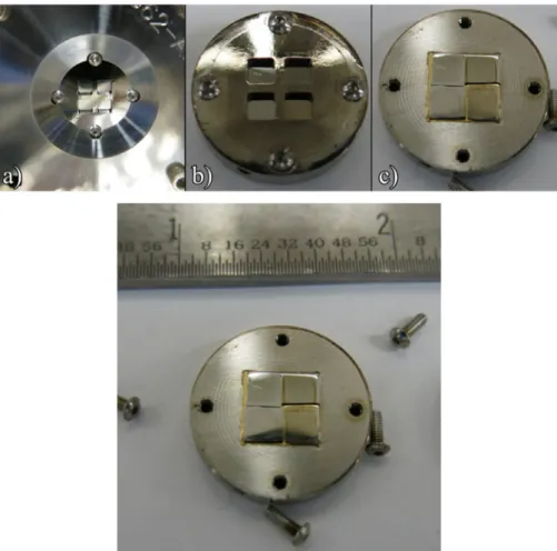
The alloy compositions are shown inTable 1. The alloys were sec- tioned into 3.5−4 mm × 3.5−4 mm-sized samples using a linear precision saw. Note that the cross section of the T91 sample is per- pendicular to the rolling direction. They were subsequently ground and polished using SiC grinding papers with water as a lubricant down to 1200 grit, followed by polishing with diamond solution down to 0.1 µm. The samples were then mounted onto the irradiation holder as depicted inFig. 1. The high energy ion irradiation was conducted at the center for accelerator mass spectrometry (CAMS) at Lawrence Li- vermore National Laboratory. The four alloys were irradiated with a rastered beam of 70 MeV Fe9+bombarding ions, at 452 °C to a total dose of 20.68 displacement per atom (dpa). The dose was calculated at the depth where 5% of the peak implantation occurred. The average current was 19.47 nC/s. The irradiation process was completed in 15.55 h while the temperature was monitored using an IR camera and a thermocouple mounted behind the sample. The beam current and profile were measured using an array of micro Faraday cups. The da- mage layer was predicted to extend approximately 6.2 µm into the samples, according to the SRIM calculations shown inFig. 2. The ver- sion of the SRIM used was SRIM-2013 version in the modified Kinch- in–Pease model. Ed of 40 eV was used and the ionflux was 1015ions/
cm2. After the irradiation experiment, each sample was sectioned into two half pieces using a low speed diamond saw. Surface nanoindenta- tion and size effect studies were conducted on one half of the sample, while the other half was used for cross sectional analyses, which en- compassed cross-section nanoindentation and in situ micro-pillars compression testing.Fig. 3shows a schematic of the cross section of the sample.
2.2. Nanoindentation 2.2.1. Surface nanoindentation
Nanoindentation was performed using a micro materials (MML) indenter under depth control mode. The standard Berkovich tip was calibrated using fused silica resulting in an area function for the par- ticular tip used. The measured data (i.e. the hardness and the reduced modulus) were analyzed using the Oliver Pharr method [62]. The Table 1
Compositions of the four alloys of interest.
800H T91, NCT91 14YWT
Element G. O. Carlson (wt%) Element PNNL (wt%) Element ORNL (wt%)
Fe 45.53 Fe 89.52 Fe 82.5
Ni 31.59 Cr 8.6 Cr 14.3
Cr 20.42 Mo 0.89 W 2.32
Mn 0.76 Mn 0.37 Ti 0.27
Al 0.50 V 0.21 Y 0.19
Ti 0.57 Ni 0.09 O 0.177
Others 0.63 Others 0.32 Others 0.243
indents were performed prior to ion irradiation and after irradiation, covering the depth range from 10 nm to 1000 nm. A separation distance of 5–10μm was used between the indents ensuring no plastic zone in- teractions. With the obtained nanoindentation data, indentation size effect studies were performed on the surface samples before and after irradiation.
The continuous stiffness measurement (CSM) technique for na- noindentation was also used in this study. These experiments were carried out using a Keysight (formerly Agilent) G200 nanoindenter. In CSM indentation, an oscillating sinusoidal force is imposed on the nominally increasing loading segment of the indentation cycle. This allows the contact stiffness, and therefore the indentation hardness and modulus, to be measured as a function of indenter displacement con- tinuously throughout the loading segment of the indentation. Arrays consisting of 25 indentations were made in both the irradiated and the
unirradiated regions of the sample; all indentations were conducted in displacement control mode to a maximum displacement of 2μm with a displacement rate of 10 nm/sec. Indents were positioned 50μm apart to ensure that the plastic zones beneath the surface did not interact. The CSM conditions used were a frequency of 45 Hz and an amplitude of 1 nm.
2.2.2. Cross-section nanoindentation
Each of the four irradiated samples was mounted next to stainless steel thin foils to prevent edge rounding thereby ensuring symmetric indents and aflat irradiated area. The same grinding and polishing procedures mentioned previously were applied to achieve deformation- free surfaces for nanoindentation. A series of indentation measurements Fig. 1.Sample configuration for ion irradiation (a) in CAMS beamline (b) after irradiation (with cover) (c) after irradiation (without cover) (d) with scale bar.
Fig. 2.SRIM calculation of ion irradiation using 70 MeV Fe ions projectiles and Fe as target.
Fig. 3.Schematic of the cross section of the sample showing variation of me- chanical testing conditions (Figure not drawn to scale).
were performed on the irradiated cross-section samples in order to analyze the hardness change as a function of depth from the sample surface. Indents on the non-irradiated edge were also conducted for a direct comparison. All indents were performed under depth-controlled mode at a depth of 200 nm. The indents were also spaced approxi- mately 5–10μm apart to prevent plastic zone interactions.
2.3. Micro-pillars fabrication and in situ microcompression testing An FEI Quanta dual beam scanning electron microscope and focused ion beam (FIB-SEM) was used to fabricate pillars with the dimensions of either 3μm × 3μm × 6μm (T91 and NCT91) or 2μm × 2μm × 4μm (14YWT and 800H). Six pillars were fabricated in each of the cross- section samples with three pillars in the irradiated area and three pillars in the non-irradiated area, as shown inFig. 3. For the 800H alloy, with relatively large grain size, electron backscattered diffraction (EBSD) was used to identify large grains for pillar locations. A large grain containing both the unirradiated and the irradiated material was se- lected for pillar fabrication in order to allow direct comparisons be- tween the control and the irradiated pillars within the same grain.In situuniaxial compression was performed utilizing a Hysitron PI-85 pico- indenter on the FIB-SEM fabricated pillars in the depth-controlled mode at the displacement rate of 10 nm/s using an indenter with aflat tip to obtain stress-strain curves for yield stress calculations[55].
2.4. X-ray diffraction
X-ray diffraction measurements were carried out on the same irra- diated samples used for the micro-mechanical tests using a special high- resolution double-crystal diffractometer dedicated to line-profile-ana- lysis[66]. The incident angle wasfixed at 20° on a stationary specimen.
The detection depth of CoKα1radiation at this angle is∼4μm, and so the detected X-rays originate from the relativelyflat region of the da- mage profile inFig. 3. The diffractometer was operated with a sealed Co X-ray tube of 0.4 × 8 mm2fine line-focus running at 30 kV and 35 mA with a wavelength of λ= 0.1789 nm. The primary beam was mono- chromatised by a plane Ge monochromator using the (220) reflection. A slit of∼0.2 mm was inserted before the monochromator in order to select the CoKα1line and to remove the CoKα2contribution. The in- cident X-ray beam was positioned on the specimen surface using a low depth-resolution microscope and was observed to illuminate an area of
∼0.2 × 1.0 mm on the specimen surface. The scattered X-rays were detected by two imaging plate (IP) detectors with a linear spatial re- solution of 50μm. The IPs were placed at the distance of 193 mm from the specimen covering an angular range of 25° < 2θ< 170°. The dif- fraction patterns were obtained by integrating the intensity distribu- tions along the corresponding Debye–Scherrer arcs on the IPs and are shown inFig. 4. Due to the plane Ge monochromator equipped with a 0.2 mm slit at a distance of ∼150 mm from the X-ray source, the in- strumental broadening effect of this setup was negligible[66], and can therefore be used for reliable line profile analysis.
In order to provide control samples free from surface deformation, a
∼2 × 1 mm window was electropolished in specimens cut from in the bulk non-irradiated material. An electrolyte of 5% perchloric acid and 95% methanol was used and the time was controlled in order to remove
∼100μm from the surface. This type of sample preparation has the advantage over mechanical polishing methods that it should not in- troduce any additional deformation in the surface of the samples and so provides a reliable reference value for the non-irradiated state. Due to a lack of control of the electropolishing technique and the relatively thin damage layer, it was not possible to electropolish the irradiated samples after irradiation. However, the careful polishing of the samples prior to irradiation would mean that any surface deformation would be minimal and the relatively large penetration depth of the Co X-rays ensures that the main contribution to the line broadening is from the irradiation- induced damage.
The diffraction patterns were evaluated by the CMWP procedure [64]. The method is based on physically well-established profile func- tions theoretically calculated for different specific lattice defects, in particular for the coherently scattering domain size and dislocations [64–68]. The procedure is free from any empirical adjustment para- meters and has been shown to provide excellent correlation with TEM dislocation densities in a wide range of density values[67].
3. Results
3.1. Nanoindentation
3.1.1. Surface nanoindentation results and size effect study
Fig. 5ashows the hardness of the surface samples as a function of indentation depth. Both the control and the irradiated hardness mea- surements of each sample are displayed in the same plot for compar- ison.Table 2provides the average of hardness of all four alloys at a penetration depth of 1000 nm before and after irradiation, along with the increase in hardness in each of the alloy due to the ion irradiation.
Although significant irradiation hardening was observed in the 800H and T91 alloys, a negligible hardening effect was observed in the NCT91 and 14YWT alloys, which is within the error of the measure- ments.
According to the hardness profiles, the 800H alloy appeared to be strongly size affected while the other samples were not.“Indentation size effect” is the phenomenon where hardness increases with de- creasing penetration depth, making the measurements deviate from macroscopic hardness values. The size effect was characterized using the Nix and Gao model (Eq. (1))[64].H0, which is the hardness in the limit of infinite depth, and h*, which is a characteristic length de- pending of the shape of the indenter, are the main parameters de- scribing the size effect behavior. H0 and h* can be calculated after plottingH2vs. 1/h. Typically, materials with a low size effect have a lowh*, and materials with a large size effect have a highh*. The cal- culatedh*values for all of the samples are tabulated inTable 3. The negativeh*values are due to the slight hardness increase as a function of penetration depth, which is presumably due to small measurement errors within the error bars. However, if the value of the negativeh*is below−50 nm, the opposite phenomenon is present i.e. indentation size effect where hardness decreases with decreasing penetration depth.
= + H H
h 1 h*
0 (1)
Fig. 5bshows the hardness measurements obtained using the CSM technique. The average of 25 indentations is shown and error bars re- present one standard deviation of the mean. Significant irradiation-in- duced hardening can be observed in the 800H alloy and the T91, however the NCT91 and the 14YWT show no significant irradiation induced hardening. It should be noted that there is a slight hardening effect in the 14YWT sample, which may be attributed to sample pre- paration or carbon contamination as highlighted in [71]in the low depth indents and microstructural heterogeneity beyond the surface region. In all samples and conditions, an indentation size effect was observed.
3.1.2. Cross-section nanoindentation
Fig. 6shows hardness profiles from the cross-sectional samples, providing post-irradiation hardness measurements as a function of distance from the surface. A significant increase in hardness was ob- served in the irradiated regions of the 800H and T91 alloys. The hardness of 800H and T91 increased from 2.8 GPa to 4.2 GPa and from 3.8 GPa to 5.1 GPa, respectively. However, this characteristic was not observed in the NCT91 and 14YWT alloys. According to the hardness profiles, the hardness values did not deviate significantly from the average of∼4.5 GPa for NCT91 and∼6.9 GPa for 14YWT. The distinct
hardness drop shown corresponds to the transition of the irradiated to the non-irradiated regions in the cross section of the sample. The 800H cross-section hardness profile suggests that the irradiation depth is approximately 6μm. This agrees well with the SRIM predictions of 6.2μm. The blue and the red lines inFig. 6correspond to the average hardness at the same indentation depth (200 nm) in the control and the irradiated regions of the sample surface, respectively. While the surface hardness measurements reasonably match with the cross section hard- ness measurements for 800H, T91 and NCT91, the agreement was not observed in the case of 14YWT due to the anisotropic microstructure.
3.2. Microcompression
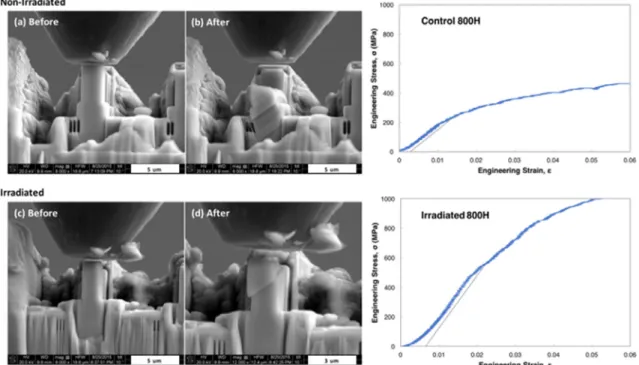
Engineering stress and strain curves were obtained from micro- compression testing. By taking the surface interactions between the tip and the pillars into account a 0.2% strain line parallel to the elastic region was plotted to obtain the offset yield point. Images of pillars in the non-irradiated and the irradiated area of the cross-sectional 800H sample before and after compression are shown in Fig. 7. The corre- sponding stress-strain curves obtained from the load-displacement data and yield stresses are plotted next to each of the pillars for comparison.
The yield stresses of the successfully compressed pillars fabricated in the non-irradiated and the irradiated area of the four samples are provided inTable 4. Pillars with possible experimental errors such as misalignment during the compression are excluded from the table.
3.3. X ray diffraction
Fig. 4shows the measured XRD patterns from non-irradiated and irradiated samples. Due to the large grain size of the 800H alloy, it was not possible to get sufficient statistics for accurate CMWP analysis and so the XRD investigation focused on the smaller grained BCC materials.
The calculated profiles from CMWP are overlayed on the measured profiles inFig. 4. Good agreement was observed between the measured and calculated profiles for all the measured samples. The micro- structural parameters from the CMWP analysis are shown inTable 5.
The strongest increase in the dislocation density was observed in the T91 specimen, which showed a 5-fold increase in dislocation density after irradiation. In contrast, the nanocrystalline T91 showed an almost negligible increase in dislocation density after irradiation, considering the error in the values. The dislocation density of the 14YWT alloy was observed to double after irradiation, although the change in dislocation density was significantly less than that observed in T91.
In order to qualitatively assess the diffraction patterns using the full width at half maximum (FWHM) of the reflections, modified Williamson-Hall (mWH) plots were created using the measured profiles and are shown in Fig. 9 [65]. The figures show that for each in- vestigated sample the slope of the mWH plot increases after irradiation;
the change is large for T91, and small for NCT91 and 14YWT. Quali- tatively, the slope of a mWH plot increases a function of dislocation density, as Eq. (5) in[65]demonstrates. Thus, the qualitative trends
60 90 120 150
100 1000 (c)
IntensityA.U.
2θo
60 90 120 150
100 1000 (a)
IntensityA.U.
2θo
60 90 120 150
100 1000 (b)
IntensityA.U.
2θo
60 90 120 150
100 1000 (d)
IntensityA.U.
2θo
60 90 120 150
100 1000 (e)
IntensityA.U.
2θo 60 90 120 150
100 1000 (f)
IntensityA.U.
2θo
T91 non-irradiated T91 irradiated
NCT91 non-irradiated NCT91 irradiated
14YWT non-irradiated 14YWT irradiated
Fig. 4.Measured (open circles) and CMWP calculated (red lines) XRD patterns (a) non-irradiated T91, (b) irradiated T91, (c) non-irradiated NCT91, (d) irradiated NCT91, (e) non-irradiated 14YWT and (f) irradiated 14YWT.
shown by the mWH plots for the dislocation densities are in agreement with the results of the quantitative CMWP analysis.
Some interesting trends were also observed in the other micro- structural parameters determined from CMWP, see Table 5. The M parameter shows the dipole character of the dislocations and can be considered as a measure of the degree of dislocation arrangement present in the sample.Mis observed to decrease by approximately half in all three specimens after irradiation, indicating an increase in the ordering of irradiation-induced dislocations. The q parameter is a measure of thehkldependence of the line broadening and can be used to determine the edge/screw nature of dislocations in cubic materials [72]. In BCC steels, the average screw/edge character would give q=∼1.8 with lower or higher values indicating a larger edge or screw ratio respectively. Negligible changes in theqparameter are observed after irradiation in all samples, however a lower average value is ob- served in T91 and NCT91 alloys than in 14YWT indicating 14YWT has a higher ratio of screw dislocations and the T91 alloy have a higher edge ratio. The errors for all parameters are shown inTable 5, and are de- termined by running the evaluation several times. CMWP was recently extended to combine the Marquardt–Levenberg optimisation method with a Monte-Carlo statistical procedure in order to find the global minimum of the physical parameters. The errors, as indicated in Table 5, are given by the Monte-Carlo procedure as the variations of the physical parameters when the weighted sum of squared residuals be- tween measured and calculated pattern data exceed 3.5%. This is the confidence parameter set in the present application of CMWP and more details will be given in Ref[73].
4. Discussion
Hardness saturates after a certain dose at a temperature in in- dentation testing (typically around 10 dpa) as it has been shown by others[61], which is the same way as yield stress saturates at a similar dose on materials[51,74–75]. Hardness as well as yield stress cannot increase indefinitely due to the fact that there are only a certain number of defects that can befit within a specific volume. From the current results we can conclude that for the alloys of interest, hardness satu- rates either at 20 dpa or lower (likely at 10 dpa) as has previously been observed in other materials such as steels[51,61,74–75].
Comparing the size effect parameters of the different samples pro- vides insight into the materials microstructure. It is found that the softer FCC material, with a large grain size and low defect density, experi- ences a large size effect while the BCC materials, with afine micro- structure and significant defect density, have a lower size effect. This is in good agreement with Nix and Gao as well as others[76]and can be explained by the fact that fully annealed, large-grained materials gen- erally have less stored dislocations and dislocation pinning points. It is also observed that the size effect is significantly reduced with the ad- dition of radiation damage, in agreement with these observations. It does raise the question, however, how macroscopic properties can be Fig. 5a.Quasi-static indentation hardness as a function of indentation depth
including unirradiated and irradiated samples.
Table 2
Hardness measurements obtained by nanoindentation on the surface.
1000 nm depth Hardness (GPa) Hardness (GPa)
800H Irradiated 3.63 ± 0.07 1.31
Control 2.32 ± 0.08
T91 Irradiated 4.77 ± 0.16 1.76
Control 3.01 ± 0.02
NCT91 Irradiated 4.28 ± 0.18 0.15
Control 4.13 ± 0.11
14YWT Irradiated 7.04 ± 0.23 0.14
Control 6.90 ± 0.39
Table 3
Nix and Gao's h* values before and after irradiation.
Sample Before irradiation After irradiation
h*(nm) ISE h*(nm) ISE
800H 627 Strong 201 Moderate
T91 −2.97 None −28.4 None
NCT91 16 None 41.5 None
14YWT −8.06 None −20.4 None
|h*| (nm) ISE
>250 Strong
150–250 Moderate
50–150 Weak
<50 None
derived from nanoscale tests if the size effect changes as a function of irradiation damage. A simpleΔH value will not allow for the estimation of macroscopic hardness values and therefore yield strength. It is therefore a requirement that the size effect is known in order to esti- mate macroscopic properties for a given material. However, there is rarely sufficient ion-irradiated material available to perform a size ef- fect study, which makes this approach difficult. However, the fact that minimal size effect was observed in the irradiated material leads to the assumption that the nanohardness is representative of the bulk mate- rial. Therefore, it is possible to measure the hardness of the irradiated material at the small scale with hardness measured at the larger scale on bulk non-irradiated material in order to calculate the delta hardness.
A similar technique was outlined in[77].
The hardness measurements obtained using the CSM method, in the surface of the sample agree reasonably well with the surface indenta- tion results obtained from the quasi-static technique with the exception of the 14YWT material. The microstructure of the 14YWT had a small
grain size with grains ranging from as small as 100 nm to 1 µm in size.
Due to the difference in the average grain sizes and precipitate dis- tributions, it is possible to suggest that the QS experiments were made in a region with a low precipitation density and/or a large average grain size and the CSM experiments were made in a region of the sample with a high density of precipitates and/or a small average grain size. This would explain the difference in the hardness measured from each technique.
A size effect is observed for all samples in both the irradiated and unirradiated conditions. In this technique, the hardness is continuously being measured whilst the indenter is penetrating deeper into the ma- terial. As the displacement increases, the volume of material being sampled beneath the indenter (i.e. the plastic zone) will evolve from containing purely damaged material, to a combination of unirradiated and irradiated untilfinally at large penetration depths the unirradiated material will dominate the hardening response and the irradiated and unirradiated hardness curves will converge. At the depth at which this Fig. 5b.CSM indentation hardness measured from the surface of the sample.
transition occurs (i.e changing from purely irradiated to a mixture), a change in the hardness behavior can be observed. This is clearer for the T91 and the 14YWT samples (see irradiated hardness curves of T91 and 14YWT inFig. 5b) where a distinct‘kink’in the hardness curve can be observed. A similar‘kink’can be observed in the unirradiated hardness curve for the 14WYT sample. This can be explained from the geometry of the irradiation set up. Indentations in the unirradiated region of the sample were taken from the surface of the sample that was shielded from the ion-beam (Fig. 1). In the case of the 14YWT sample, the uni- rradiated portion of the sample was clamped down during the irra- diation. This‘clamping’mechanism created mechanical damage to the surface of the material which resulted in a distinct ‘kink’in the uni- rradiated nanoindentation hardness measurements. As a result, the CSM
non-irradiated hardness data for the 14YWT sample was not used for comparison.
Microcompression testing revealed significantly higher yield stresses in 800H and T91 in the irradiated area than the control area.
However, a much smaller difference in the yield stress values was ob- tained in the control and the irradiated area of NCT91 and 14YWT. This agrees well with the nanoindentation results, confirming irradiation hardening in 800H and T91 but not in NCT91 and 14YWT. Although the focus of this paper is not to compare the mechanical property evolution resulting from ion irradiation to that resulting from neutron irradiation, it is worth noting that, as an example, a considerable in- crease in yield stress has also been observed in neutron irradiated T91 [78]. Along with the increase in yield stress, the increase in hardness Fig. 6.Hardness and modulus profiles of cross-sectional samples as a function of distance from the edge (Penetration depth of 200 nm).
due to irradiation hardening was observed in neutron irradiated T91 [79], thus confirming the similarities between ion irradiated and neu- tron irradiated alloys in this aspect of mechanical property evolution.
In order to cross compare between nanoindentation and micro- compression, and relate both small-scale mechanical testing methods, yield stress can be obtained from nanoindentation by converting Berkovich hardness (Hb) to Vickers hardness (Hv) (Eq. (2)) then to yield stress (σy) (Eq. (3))[80].
=
HV 94.5H (2)
= −
σy 2.82Hv 144 (3)
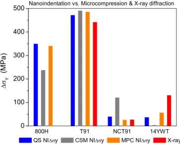
Fig. 8andTable 6compares the difference in yield stresses of the four alloys obtained from nanoindentation and microcompression be- fore and after irradiation. The agreement between the two testing methods results in the increase in confidence in thefield of small-scale mechanical testing. Discrepancies between the two testing methods could be due to the different nature of the stress states for each method.
While nanoindentation is associated with triaxial stress state, micro- compression is a uniaxial type of testing.
The initial dislocation density, as measured by CMWP, of the NCT91 alloy was the highest of all 3 BCC samples, and was in fact higher than the dislocation density of the other alloys after irradiation (Table 5).
This is to be expected due to the severe plastic deformation technique used to fabricate these nanocrystalline alloys [81]. The resulting na- nocrystalline grain structure, with sub-micron grain size, is likely to be responsible for the irradiation resistance of this alloy due to an
increased concentration of grain boundaries, which are know to be effective neutral defect sinks[43]. This is reflected by the negligible increase in dislocation density observed in NCT91 after irradiation, which is within the error in the measurement and agrees with the negligible change in hardness observed in this alloy during na- noindentation tests. In comparison, the initial dislocation density of coarse-grained T91 was significantly lower than NCT91 as would be expected from a relatively large grained, annealed material. A previous TEM investigation has shown an extremely large spatial variation of the dislocation density in non-irradiated coarse-grained T91 [82]. In the present study, XRD provides an average dislocation density for the measured volume. This alloy experienced the largest increase in dis- location density after irradiation, a 5-fold increase, which agrees with the severe irradiation hardening observed during the small-scale me- chanical tests.
Fig. 7.Microcompression testing of 800H pillars (a) non-irradiated area (b) irradiated area.
Table 4
Yield stresses obtained from microcompression testing in the control and the irradiated area.
Sample Yield stress (MPa)
Non-irradiated Irradiated
Pillar 1 Pillar 2 Pillar 3 Average Pillar 1 Pillar 2 Pillar 3 Average
800H 250 260 250 253 ± 6 625 580 575 593 ± 28
T91 945 730 660 778 ± 145 1,435 1,125 1,230 1,263 ± 158
NCT91 950 780 N/A 865 ± 120 920 860 N/A 890 ± 42
14YWT 2380 1658 1240 1759 ± 577 1751 1830 1865 1815 ± 58
Table 5
Microstructural parameters from CMWP evaluation of XRD profiles of control and irradiated BCC alloys.
CMWP <x>area(nm) ρ(1014m−2) M q T91 Irradiated 87 ( ± 10) 14.8 ( ± 1) 5.3 ( ± 0.7) 1.6 ( ± 0.1)
Control 114 ( ± 12) 2.7 ( ± 0.2) 11 ( ± 2) 1.2 ( ± 0.2) NCT91 Irradiated 67 ( ± 8) 19.8 ( ± 1.2) 2.8 ( ± 0.4) 1.5 ( ± 0.1) Control 70 ( ± 8) 17.8 ( ± 1.2) 5.7 ( ± 0.8) 1.3 ( ± 0.2) 14YWT Irradiated 67 ( ± 8) 16.3 ( ± 1.1) 2.6 ( ± 0.4) 2.0 ( ± 0.1) Control 82 ( ± 8) 7.6 ( ± 0.6) 6.8 ( ± 1) 1.9 ( ± 0.1)
The initial dislocation density of the 14YWT alloy sits between the T91 and NCT91 control samples and agrees well with previous TEM measurements on 14YWT[83]. It is well known that in ceramics the electronic stopping power can amorphise the crystal[84]. It has pre- viously been shown that the nanocrystalline oxide dispersions particles (NCeODPs) are amorphised in heavy ion irradiated ferritic steels [85–88]. The NCeODPs in the nanocrystalline-14YWT alloy, in- vestigated here, are therefore most probably also amorphised. The X- ray scattering of the amorphous nanocrystalline particles appears in the low angle region of the diffraction pattern well below the angular range where thefirst Bragg reflections of the crystalline matrix phase appear.
The diffraction patterns inFig. 4e and f of the non-irradiated and ir- radiated 14YWT specimens show only the well-developed Bragg re- flections in the angular range of 2θ≥45°, with no hint of any scattering effects from amorphous sample fractions. The scattering of the amor- phous and crystalline parts of the sample are uncorrelated and in- dependent from each other. Therefore, it is assumed that the dislocation density obtained from the broadening of Bragg peaks is not affected by any possible amorphous NCeODPs. A relatively small increase in dis- location density after irradiation was observed compared to T91, which is most likely due to the large number of density of these ultra-fine nanoclusters present in the 14YWT microstructure. These nanoclusters act as selective sinks for defects, encouraging self-healing of damage through recombination with self-interstitial atoms[89].
The dislocation densities provided by line profile analysis are cor- related with the hardness measurements using Taylor's equation [90,91]. Theflow stress,σ, can be written as:
= +
σ σ0 aGbMT ρ (4)
whereσ0 is the flow stress before dislocations accumulate by work hardening, sometimes called the friction stress.αis a constant between zero and 1,Gis the shear modulus,MTis the Taylor factor, and b is the absolute value of the Burgers vector. In the T91 alloyσ0andGwere taken as:σ0= 415 MPa andG= 72 GPa[92]. In the 14YWT alloyσ0
andGwere taken as:σ0= 1400 MPa andG= 62 GPa[93]. The Taylor factor was taken as:MT= 3.
The evaluation for Eq. (4) gives α= 0.37( ± 0.05) for the T91, α= 0.21( ± 0.03) for the NCT91 andα= 0.2 ( ± 0.04) for the 14YWT alloys, respectively. The irradiation induced flow stress increments, calculated with these values according toEq. (4), are shown as the fourth (red) columns inFig. 8.
The larger grained 14YWT microstructure is not as effective as mitigating irradiation damage as the nanograined T91 microstructure, probably due to the fact that nanoclusters are less efficient defect sinks than grain boundaries. Although the scatter in the data is greater, most likely due to a more heterogeneous microstructure, this is also reflected in the nanoindentation data (Fig. 5a) that shows a larger increase in hardness after irradiation in the 14YWT alloy than in NCT91. In addi- tion, a similar trend is observed in the yield stress as determined from the microcompression experiments (Fig. 8), although this is not ob- served in the calculated yield stress obtained from the nanoindentation measurements. This could be because of the different types of stress state of each testing technique.
5. Conclusion
In this study, surface and cross-sectional nanoindentation mea- surements and in situ micro-pillar compression testing were used to investigate the mechanical properties of ion irradiated materials. The two different mechanical testing methods demonstrated comparable yield stress measurements and showed that the nano-grained NCT91 and 14YWT alloys are significantly more resistant to irradiation hard- ening than T91 and 800H. The results are supported by bulk XRD measurements, which showed a significantly larger increase in dis- location density after irradiation in the coarse-grained T91 alloy than in nanocrystalline NCT91 and 14YWT. The complementary techniques demonstrated here will be vital in understanding the use of ion irra- diation to simulate neutron irradiation and therefore reduce the handling difficulty and complications associated with neutron irradia- tion, which is essential for the high damage levels expected in Gen-IV reactors.
Acknowledgments
This work was funded by DOE-NE Integrated Research Project (IRP).
Work at the Molecular Foundry was supported by the Office of Science, Office of Basic Energy Sciences, of the U.S. Department of Energy under Contract No. DE-AC02-05CH11231. The authors gratefully acknowl- edge the Biomolecular Nanotechnology Center (BNC) facilities at UC Berkeley. Alistair Garner, Tamas Ungar and Michael Preuss acknowl- edgefinancial support from EPSRC (EP/I005420/1 and EP/L025981/
1).
0 100 200 300 400 500
Δσ Y
(M Pa )
QS NIΔσy CSM NIΔσy MPC NIΔσy X-ray 800H T91 NCT91 14YWT Nanoindentation vs. Microcompression & X-ray diffraction
Fig. 8.Difference in yield stresses before and after irradiation obtained from nanoindentation and microcompression experiments. (For interpretation of the references to color in the text, the reader is referred to the web version of this article.)
0 2 4 6
0.00 0.02 0.04
NCT91 non-irradiated irradiated (b)
KC1/2 [1/nm]
FWHM[1/nm]
0 2 4 6
0.00 0.02 0.04
T91 non-irradiated irradiated (a)
KC1/2 [1/nm]
FWHM[1/nm]
0 2 4 6
0.00 0.02 (c) 0.04
14YWT non-irradiated irradiated KC1/2 [1/nm]
FWHM[1/nm]
Fig. 9.Modified Williamson Hall plots for T91, NCT91 and 14YWT measured from experimental XRD profiles.
References
[1] L.K. Mansur, et al., Materials needs for fusion, generation IVfission reactors and spallation neutron sources–similarities and differences, J. Nucl. Mater. 329 (2004) 166–172.
[2] K.L. Murty, I. Charit, Structural materials for Gen-IV nuclear reactors: challenges and opportunities, J. Nucl. Mater. 383 (1) (2008) 189–195.
[3] T.R. Allen, et al., Materials challenges for generation IV nuclear energy systems, Nucl. Technol. 162 (3) (2008) 342–357.
[4] P. Yvon, F. Carré., Structural materials challenges for advanced reactor systems, J.
Nucl. Mater. 385 (2) (2009) 217–222.
[5] I. Chant, K.L. Murty, Structural materials issues for the next generationfission re- actors, JOM 62 (9) (2010) 67–74.
[6] StevenJ. Zinkle, G.S. Was, Materials challenges in nuclear energy, Acta Mater. 61 (3) (2013) 735–758.
[7] Pascal Yvon, et al., Structural materials for next generation nuclear systems: chal- lenges and the path forward, Nucl. Eng. Des. 294 (2015) 161–169.
[8] Giorgio Locatelli, Mauro Mancini, Nicola Todeschini, Generation IV nuclear re- actors: current status and future prospects, Energy Policy 61 (2013) 1503–1520.
[9] Concetta Fazio, et al., Innovative materials for Gen IV systems and transmutation facilities: the cross-cutting research project GETMAT, Nucl. Eng. Des. 241 (9) (2011) 3514–3520.
[10] K. Tuček, et al., Generation IV reactor safety and materials research by the institute for energy and transport at the european commission's joint research centre, Nucl.
Eng. Des. 265 (2013) 1181–1193.
[11] Pascal Yvon, Structural Materials for Generation IV Nuclear Reactors, Woodhead Publishing, 2016.
[12] R.L. Klueh, et al., Ferritic/martensitic steels–overview of recent results, J. Nucl.
Mater. 307 (2002) 455–465.
[13] R. Schaeublin, D. Gelles, M. Victoria, Microstructure of irradiated ferritic/marten- sitic steels in relation to mechanical properties, J. Nucl. Mater. 307 (2002) 197–202.
[14] R.L. Klueh, A.T. Nelson, Ferritic/martensitic steels for next-generation reactors, J.
Nucl. Mater. 371 (1) (2007) 37–52.
[15] Plesiutschnig, Ernst, Ferritic phase transformation to improve creep properties of martensitic high Cr steels, Scr. Mater. 122 (2016) 98–101.
[16] J. Henry, S.A. Maloy, Irradiation-resistant ferritic and martensitic steels as core materials for Generation IV nuclear reactors, Struct. Mater. Gen. IV Nucl. Reactors (2016) 329.
[17] G. Gupta, et al., Microstructural evolution of proton irradiated T91, J. Nucl. Mater.
351 (1) (2006) 162–173.
[18] R.E. Clausing, et al., Radiation-induced segregation in HT-9 martensitic steel, J.
Nucl. Mater. 141 (1986) 978–981.
[19] Z. Jiao, G.S. Was, Segregation behavior in proton-and heavy-ion-irradiated ferri- tic–martensitic alloys, Acta Mater. 59 (11) (2011) 4467–4481.
[20] JanelleP. Wharry, et al., Radiation-induced segregation and phase stability in fer- ritic–martensitic alloy T 91, J. Nucl. Mater. 417 (1) (2011) 140–144.
[21] JanelleP. Wharry, GaryS. Was, A systematic study of radiation-induced segregation in ferritic–martensitic alloys, J. Nucl. Mater. 442 (1) (2013) 7–16.
[22] KevinG. Field, et al., Dependence on grain boundary structure of radiation induced segregation in a 9wt.% Cr model ferritic/martensitic steel, J. Nucl. Mater. 435 (1) (2013) 172–180.
[23] T. Lauritzen, A. Withop, U.E. Wolff, Swelling of austenitic stainless steels under fast neutron irradiation at elevated temperatures, Nucl. Eng. Des. 9 (2) (1969) 265–268.
[24] E.A. Kenik, Radiation-induced segregation in irradiated Type 304 stainless steels, J.
Nucl. Mater. 187 (3) (1992) 239–246.
[25] E.A. Kenik, T. Inazumi, G.E.C. Bell, Radiation-induced grain boundary segregation and sensitization of a neutron-irradiated austenitic stainless steel, J. Nucl. Mater.
183 (3) (1991) 145–153.
[26] Yukinori Yamamoto, et al., Creep-resistant, Al2O3-forming austenitic stainless steels, Science 316 (5823) (2007) 433–436.
[27] Yukinori Yamamoto, et al., Alloying effects on creep and oxidation resistance of austenitic stainless steel alloys employing intermetallic precipitates, Intermetallics 16 (3) (2008) 453–462.
[28] Shigeharu Ukai, Masayuki Fujiwara, Perspective of ODS alloys application in nu- clear environments, J. Nucl. Mater. 307 (2002) 749–757.
[29] A. Alamo, et al., Assessment of ODS-14% Cr ferritic alloy for high temperature applications, J. Nucl. Mater. 329 (2004) 333–337.
[30] G.R. Odette, M.J. Alinger, B.D. Wirth, Recent developments in irradiation-resistant steels, Annu. Rev. Mater. Res. 38 (2008) 471–503.
[31] JoachimH. Schneibel, et al., Ultrafine-grained nanocluster-strengthened alloys with unusually high creep strength, Scr. Mater. 61 (8) (2009) 793–796.
[32] Jun-Li Lin, et al., In situ synchrotron tensile investigations on 14YWT, MA957, and 9-Cr ODS alloys, J. Nucl. Mater. 471 (2016) 289–298.
[33] Ick-Soo Kim, et al., Effect of Ti and W on the mechanical properties and micro- structure of 12% Cr base mechanical-alloyed nano-sized ODS ferritic alloys, ISIJ Int.
43 (10) (2003) 1640–1646.
[34] T. Allen, et al., Advanced structural materials and cladding, MRS Bull. 34 (01) (2009) 20–27.
[35] V. De Castro, et al., Analytical characterisation of oxide dispersion strengthened steels for fusion reactors, Mater. Sci. Technol. 27 (4) (2011) 719–723.
[36] V. De Castro, et al., In-situ Fe+ion irradiation of an oxide dispersion strengthened steel, J. Phys. 522 (2014) No. 1. IOP Publishing.
[37] Vanessa De Castro, et al., TEM characterization of simultaneous triple ion implanted ODS Fe12Cr, J. Nucl. Mater. 455 (1) (2014) 157–161.
[38] Jian Gan, et al., Irradiated microstructure of alloy 800H, J. Nucl. Mater. 351 (1) (2006) 223–227.
[39] Baptiste Rouxel, et al., Influence of the austenitic stainless steel microstructure on the void swelling under ion irradiation, EPJ Nucl. Sci. Technol. 2 (2016) 30.
[40] Rongsheng Zhou, et al., Irradiation-assisted stress corrosion cracking of austenitic alloys in supercritical water, J. Nucl. Mater. 395 (1) (2009) 11–22.
[41] G.S. Was, et al., Corrosion and stress corrosion cracking in supercritical water, J.
Nucl. Mater. 371 (1) (2007) 176–201.
[42] M. Rose, A.G. Balogh, H. Hahn, Instability of irradiation induced defects in na- nostructured materials, Nucl.Instr.Methods Phys.Res.Sect.B 127 (1997) 119–122.
[43] M. Song, et al., Response of equal channel angular extrusion processed ultrafine- grained T91 steel subjected to high temperature heavy ion irradiation, Acta Mater.
74 (2014) 285–295.
[44] RandyK. Nanstad, et al., High temperature irradiation effects in selected generation IV structural alloys, J. Nucl. Mater. 392 (2) (2009) 331–340.
[45] Vanessa de Castro, et al., Effects of single-and simultaneous triple-ion-beam irra- diation on an oxide dispersion-strengthened Fe12Cr steel, J. Mater. Sci. 50 (5) (2015) 2306–2317.
[46] R.S. Nelson, D.J. Mazey, J.A. Hudson, The use of ion accelerators to simulate fast neutron-induced voidage in metals, J. Nucl. Mater. 37 (1) (1970) 1–12.
[47] G.L. Kulcinski, A.B. Wittkower, G. Ryding, Use of heavy ions from a tandem ac- celerator to simulate highfluence, fast neutron damage in metals, Nucl. Instrum.
Methods 94 (2) (1971) 365–375.
[48] N.H. Packan, K. Farrell, J.O. Stiegler, Correlation of neutron and heavy-ion damage:
I. the influence of dose rate and injected helium on swelling in pure nickel, J. Nucl.
Mater. 78 (1) (1978) 143–155.
[49] M.B. Lewis, et al., Improved techniques for heavy-ion simulation of neutron ra- diation damage, Nucl. Instrum. Methods 167 (2) (1979) 233–247.
[50] C. Abromeit, Aspects of simulation of neutron damage by ion irradiation, J. Nucl.
Mater. 216 (1994) 78–96.
[51] G.S. Was, et al., Emulation of neutron irradiation effects with protons: validation of principle, J. Nucl. Mater. 300 (2) (2002) 198–216.
[52] MarquisA. Kirk, et al., In situ transmission electron microscopy and ion irradiation of ferritic materials, Microsc. Res. Tech 72 (3) (2009) 182–188.
Table 6
Quasi-static (QS) and continuous stiffness measurement (CSM) indentation data for four alloys of interest.
QS Hb(GPa) Hv(GPa) NIσy(MPa) NIΔσy(MPa) MPCσy(MPa) MPCΔσy(MPa)
800H Irradiated 3.63 ± 0.07 343 ± 6.62 853 ± 18.7 349 593 ± 28 340
Control 2.32 ± 0.08 219 ± 7.56 504 ± 21.3 253 ± 6
T91 Irradiated 4.77 ± 0.16 451 ± 15.1 1158 ± 42.6 471 1,263 ± 158 485
Control 3.01 ± 0.02 284 ± 1.89 687 ± 5.33 778 ± 145
NCT91 Irradiated 4.28 ± 0.18 404 ± 17.0 1025 ± 48.0 39 890 ± 42 25
Control 4.13 ± 0.11 390 ± 10.4 986 ± 29.3 865 ± 120
14YWT Irradiated 7.04 ± 0.23 665 ± 21.7 1761 ± 61.3 36 1,815 ± 58 56
Control 6.90 ± 0.39 652 ± 36.9 1725 ± 104 1,759 ± 577
CSM Hb(GPa) Hv(GPa) NIσy(MPa) NIΔσy(MPa) MPCσy(MPa) MPCΔσy(MPa)
800H Irradiated 4.12 ± 0.16 389 ± 15.12 984 ± 42.3 237 593 ± 28 340
Control 3.23 ± 0.08 305 ± 7.56 747 ± 21.3 253 ± 6
T91 Irradiated 5.06 ± 0.12 478 ± 11.34 1234 ± 32.0 490 1,263 ± 158 485
Control 3.22 ± 0.07 304 ± 6.62 744 ± 18.7 778 ± 145
NCT91 Irradiated 4.67 ± 0.11 441 ± 10.4 1131 ± 29.3 120 890 ± 42 25
Control 4.22 ± 0.14 399 ± 13.2 1011 ± 37.3 865 ± 120
14YWT Irradiated 7.09 ± 0.08 670 ± 7.56 1775 ± 21.3 2 1,815 ± 58 56
Control 7.08 ± 0.12 669 ± 11.3 1773 ± 11.3 1,759 ± 577
[53] A. Etienne, et al., Dislocation loop evolution under ion irradiation in austenitic stainless steels, J. Nucl. Mater. 400 (1) (2010) 56–63.
[54] G.S. Was, et al., Emulation of reactor irradiation damage using ion beams, Scr.
Mater. 88 (2014) 33–36.
[55] MichaelD. Uchic, DennisM. Dimiduk, A methodology to investigate size scale effects in crystalline plasticity using uniaxial compression testing, Mater. Sci. Eng. 400 (2005) 268–278.
[56] P. Hosemann, et al., Nanoindentation on ion irradiated steels, J. Nucl. Mater. 389 (2) (2009) 239–247.
[57] P. Hosemann, et al., An exploratory study to determine applicability of nano- hardness and micro-compression measurements for yield stress estimation, J. Nucl.
Mater. 375 (1) (2008) 135–143.
[58] Peter Hosemann, et al., Issues to consider using nano indentation on shallow ion beam irradiated materials, J. Nucl. Mater. 425 (1) (2012) 136–139.
[59] Daniel Kiener, et al., Application of small-scale testing for investigation of ion- beam-irradiated materials, J. Mater. Res. 27 (21) (2012) 2724–2736.
[60] D.E.J. Armstrong, et al., Small-scale characterisation of irradiated nuclear mate- rials: part II nanoindentation and micro-cantilever testing of ion irradiated nuclear materials, J. Nucl. Mater. 462 (2015) 374–381.
[61] A. Lupinacci, et al., Characterization of ion beam irradiated 304 stainless steel utilizing nanoindentation and Laue microdiffraction, J. Nucl. Mater. 458 (2015) 70–76.
[62] WarrenCarl Oliver, GeorgeMathews Pharr, An improved technique for determining hardness and elastic modulus using load and displacement sensing indentation experiments, J. Mater. Res. 7 (06) (1992) 1564–1583.
[63] MichaelD. Uchic, et al., Sample dimensions influence strength and crystal plasticity, Science 305 (5686) (2004) 986–989.
[64] Gábor Ribárik, Tamás Ungár, Characterization of the microstructure in random and textured polycrystals and single crystals by diffraction line profile analysis, Mater.
Sci. Eng. 528 (1) (2010) 112–121.
[65] T. Ungár, A Borbély, The effect of dislocation contrast on x‐ray line broadening: a new approach to line profile analysis, Appl. Phys. Lett. 69 (21) (1996) 3173–3175.
[66] T. Ungar, et al., Dislocations, grain size and planar faults in nanostructured copper determined by high resolution x-ray diffraction and a new procedure of peak profile analysis, Acta Mater. 46 (10) (1998) 3693–3699.
[67] T. Ungár, H. Mughrabi, D. Ronnpagel, M. Wilkens, X-ray line broadening study of the dislocation cell structurein deformed [001]-oriented copper single crystals, Acta Metall. 32 (3) (1984) 333–342.
[68] Tamás Ungár, et al., Crystallite size distribution and dislocation structure de- termined by diffraction profile analysis: principles and practical application to cubic and hexagonal crystals, J. Appl. Crystallogr. 34 (3) (2001) 298–310.
[69] Levente Balogh, Fei Long, Daymond Mark R, Contrast factors of irradiation-induced dislocation loops in hexagonal materials, J. Appl. Crystallogr. 49 (6) (2016) 2184–2200.
[70] T. Seymour, et al., Evolution of dislocation structure in neutron irradiated Zircaloy- 2 studied by synchrotron x-ray diffraction peak profile analysis, Acta Mater. 126 (2017) 102–113.
[71] G.S. Was, et al., Resolution of the carbon contamination problem in ion irradiation experiments, Nucl. Instrum. Methods Phys. Res. Sect. B 412 (2017) 58–65.
[72] T. Ungár, et al., The contrast factors of dislocations in cubic crystals: the dislocation model of strain anisotropy in practice, J. Appl. Crystallogr. 32 (5) (1999) 992–1002.
[73] G. Ribarik, B Joni, T Ungar, in preparation.
[74] S.A. Maloy, et al., The mechanical properties of 316L/304L stainless steels, Alloy 718 and Mod 9Cr–1Mo after irradiation in a spallation environment, J. Nucl. Mater.
296 (1) (2001) 119–128.
[75] C. Pokor, et al., Irradiation damage in 304 and 316 stainless steels: experimental investigation and modeling. Part II: irradiation induced hardening, J. Nucl. Mater.
326 (1) (2004) 30–37.
[76] GeorgeM. Pharr, ErikG. Herbert, Yanfei Gao, The indentation size effect: a critical examination of experimental observations and mechanistic interpretations, Annu.
Rev. Mater. Res. 40 (2010) 271–292.
[77] Peter Hosemann, Small-scale mechanical testing on nuclear materials: bridging the experimental length-scale gap, Scr. Mater. (2017).
[78] B. Long, Y. Dai, N. Baluc, Investigation of liquid LBE embrittlement effects on ir- radiated ferritic/martensitic steels by slow-strain-rate tensile tests, J. Nucl. Mater.
431 (1) (2012) 85–90.
[79] Jing Lei, et al., Study on the mechanical properties evolution of A508-3 steel under proton irradiation, Nucl. Instrum. Methods Phys. Res. Sect. B 338 (2014) 13–18.
[80] Timothy Milot, Establishing Correlations for Predicting Tensile Properties Based on the Shear Punch Test and Vickers Microhardness Data, Thesis (2013).
[81] RuslanZ. Valiev, TerenceG. Langdon, Principles of equal-channel angular pressing as a processing tool for grain refinement, Prog. Mater Sci. 51 (7) (2006) 881–981.
[82] G. Gupta, et al., Microstructural evolution of proton irradiated T91, J. Nucl. Mater.
351 (1) (2006) 162–173.
[83] James Bentley, Hoelzer D. T., TEM characterization of tensile-tested 14YWT na- nostructured ferritic alloys, Microsc. Microanal. 14 (S2) (2008) 1416.
[84] W.J. Weber, Models and mechanisms of irradiation-induced amorphization in ceramics, Nucl. Instr. Met. Phys. Res. (2000) 98–106 B166-167.
[85] P.D. Edmondson, C.M. Parish, Y. Zhang, A. Hallen, M.K. Miller, Helium entrapment in a nanostructured ferritic alloy, Scr. Mater. 65 (2011) 731–734.
[86] P.D. Edmondson, C.M. Parish, Y. Zhang, A. Hallen, M.K. Miller, Helium bubble distributions in a nanostructured ferritic alloy, J. Nucl. Mater 434 (2013) 210–216.
[87] M.C. Brandes, L. Kovarik, M.K. Miller, M.J. Mills, Morphology, structure, and chemistry of nanoclusters in a mechanically alloyed nanostructured ferritic steel, J.
Mater. Sci 47 (2012) 3913–3923.
[88] C. Lu, Z. Lu, X. Wang, R. Xie, Z. Li, M. Higgins, C. Liu, F. Gao, L. Wang, Enhanced radiation-tolerant oxide dispersion strengthened steel and its microstructure evo- lution under helium-implantation and heavy-ion irradiation, Sci. Rep., 7 (2017) 40343–40347.
[89] Jianchao He, et al., Stability of nanoclusters in 14YWT oxide dispersion strength- ened steel under heavy ion-irradiation by atom probe tomography, J. Nucl. Mater.
455 (1) (2014) 41–45.
[90] G.I. Taylor, The mechanism of plastic deformation of crystals. Part I.—theoretical, 145 1934, pp. 362–404.
[91] A. Xu, M. Saleh, J. Davis, L. Edwards, D Bhattacharyya, In-situ micro-tensile in- vestigation of strain rate response along<100>and<110>directions in single crystal nickel, Int. J. Plast. (2018).
[92] G. Gupta, G.S. Was, Improved creep behavior of ferritic-martensitic alloy T91 by subgrain boundary density enhancement", Met. Mater. Trans. 39A (2008) 150–164.
[93] G.M. Stoica1, A.D. Stoica1, M.K. Miller, D. Ma, Temperature-dependent elastic anisotropy and mesoscale deformation in a nanostructured ferritic alloy, Nat.
Commun. (2014) DOI: 10.1038/ncomms6178.