Advances in Manufacturing (manuscript as accepted) September 2018, Volume 6, Issue 3, pp 345–353
DOI: https://doi.org/10.1007/s40436-018-0229-6
The stability of turning processes in case of periodic chip formation
Gergely Gyebr´oszki · Daniel Bachrathy · G´abor Csern´ak · Gabor Stepan
Received: 10 November 2017 / Accepted: 03 July 2018
Abstract The prediction of chatter vibration is influenced by many known com- plex phenomena, still the predictions can be uncertain. We present a new effect which can significantly change the stability properties of cutting processes. It is shown that the microscopic environment of the chip formation can have large effect on the macroscopic properties. In this work, a combined model of the sur- face regeneration effect and the chip formation is used to predict the stability in turning processes. In the chip segmentation sub-model, the primary shear zone is described with the corresponding material model along layers together with the thermodynamical behaviour. The surface regeneration is modelled by the time- delayed differential equation. Numerical simulations show, that the time scale of chip segmentation model is significantly smaller than the time scale of the turning process, therefore, averaging methods can be used. Due to the non-linear effects, the chip segmentation can decrease the average shear force leading to decreased cutting coefficients. The proper linearization of the equation of motion leads to an improved description of the cutting coefficients. It is shown that the chip seg- mentation may significantly increase the stable domains in the stability charts, furthermore, with selecting proper parameters, unbounded stability domains could be reached.
Keywords chip formation·chatter·turning·delay
The research leading to these results has received funding from the European Research Council under the European Union’s Seventh Framework Programme (FP7/2007-2013) ERC Advanced grant agreement№340889.
Gergely Gyebr´oszki, Daniel Bachrathy, Gabor Stepan Department of Applied Mechanics,
Budapest University of Technology and Economics, Budapest, Hungary Tel.: +31-1-463-1111
E-mail: gyebro@mm.bme.hu, bachrathy@mm.bme.hu, stepan@mm.bme.hu G´abor Csern´ak
MTA-BME Research Group on Dynamics of Machines and Vehicles, Budapest, Hungary E- mail: csernak@mm.bme.hu
Nomenclature
Symbol Definition [unit]
a Constant in the constitutive equation [−]
b Constant in the constitutive equation [−]
C Constant in the constitutive equation [−]
c Heat capacity
J kg−1K−1 E Modulus of elasticity [MPa]
h0 Initial chip thickness [m]
K Time scale of chip formation [s]
L Acting length of normal stress [m]
r Energy ratio [−]
Ti Temperature of the shear zone bandi[K]
Tw Temperature of the workpiece [K]
˜t Dimensionless time of chip formation [−]
ˆt Dimensionless time of turning [−]
v Cutting speed [m/s]
δ Thickness of deformation layer [m]
γi Shear strain in shear zone bandi[−]
Φ Angle of the shear plane [rad]
Ω Angular velocity of workpiece [rad/s]
ωn Natural frequency of machine-tool system [rad/s]
ρ Density
kg m−3 κ Relative damping [−]
τΦ Shear stress in case of continuous chip formation N m−2 ξ Dimensionless parameter of chip formation [−]
η Dimensionless parameter of chip formation [−]
ζ Dimensionless parameter of chip formation [−]
1 Introduction
The proper mathematical description of harmful chatter vibrations in cutting pro- cesses is still challenging and the corresponding stability charts can be unreliable even after half-century-long research [2–6]. Although the surface regeneration ef- fect (which is the main source of these self-excited vibrations) can be modelled properly by means of delayed differential equations [1], undesired vibrations are also influenced by many different phenomena. Some of them are the dynamical uncertainty [16], non-linear cutting force characteristic [19], process damping phe- nomena (explained by the flank face contact [17, 18]), velocity dependent chip thickness [14, 20, 24], influence of material microstructure [25] or short-delay ef- fect [1], nose radius effect [21], fly-over effect [22], etc.
In this work we try to highlight, that the fluctuation of the shear stress in the primary shear zone can lead to significantly different stability properties during turning.
The surface regeneration is described by the traditional delay differential equa- tion (DDE) based on the cutting force characteristic, the dynamic properties of the machine-tool/milling-tool/workpiece system and the cutter engagement conditions (chip thickness and chip width).
0 1 2 workpiece v
Φ
τ
2L chip
tool
h
0σ
Φδ
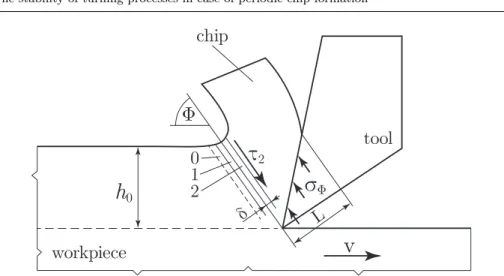
Fig. 1 Model of shear zone in case of milling. Numbers indicate shear layers.
The mathematical modelling of chip formation and segmentation is undoubt- edly a difficult task. Even simple models could lead to complex non-linear and time-delayed differential equations. Furthermore, if thermodynamical behaviour is also taken into account, the resulting model is usually high dimensional.
In recent works of Csern´ak and P´almai [8–10], a 4-dimensional non-linear sys- tem of differential equations is elaborated to model chip segmentation, which ex- hibits periodic, aperiodic and chaotic behaviour, and can be considered as one of the simplest system of differential equations describing thermomechanical effects in a satisfactory manner.
We present a coupled system of the well-known delay-differential equation of turning [1] and the 4-dimensional model of chip segmentation and examine the sta- bility properties of the resulting model. Our primary goal is to show the qualitative behaviour of the interconnected system.
This paper first focuses on a mathematical model which includes the complex thermomechanical behaviour of the shear zone. Afterwards we briefly introduce the delay-differential equation (DDE) of orthogonal turning, which is related to the phenomenon ofregenerative machine tool chatter[2]. Then, the coupled model of turning and chip formation is presented. The multi-scale nature of the coupled system is shown and a simple averaging is used to replace the dynamics of the chip formation. It is shown, that in case of periodic chip formation, the average value of shear stress may be lower than in case of continuous chip formation, thus this effect can shift the stability boundaries.
2 Model of chip formation
The description of the cutting force as a function of the chip thickness is an important part of the modelling. The 4D model of chip segmentation presented in [10] is used to examine the shear process in two deformation bands (1 and 2) of thickness δ. (See Fig. 1.) In layer 0, no deformation occurs, however, heat may flow from layer 1 to layer 0. Two equations of the system correspond to the
mechanical balance of the shear stresses and the corresponding component of the normal stress acting on the tool (σΦ,L, see Fig. 1.), while the other three energy equations describe the thermal dynamics of the layers. Here only the final system of differential equations is presented for the dimensionless shear stresses τi and shear layer temperatures Ti. For the detailed derivation see [10]. Note that the dimensionless shear stress in layer 1 is the ratio between the current shear stress and the shear stressτΦ in case of continuous chip formation.
˙
τ2(˜t) = (1−F1(τ1, T1)−F2(τ2, T2)), (1)
τ1(˜t) =p τ2(˜t) +s, (2)
T˙0(˜t) =ζ(T1(˜t)−2T0(˜t))−ξ T0(˜t), (3) T˙1(˜t) =η τ1(˜t)F1(τ1, T1)−ζ(2T1(˜t)−T2(˜t)−T0(˜t))−ξ(T1(˜t)−T0(˜t)), (4) T˙2(˜t) =η τ2(˜t)F2(τ2, T2)−(ξ+ζ)(T2(˜t)−T1(˜t)). (5) Here ˜t = t/K is the dimensionless time, where K is the time scale and ξ, ζ andηare compound dimensionless system parameters.pis a technological system parameter – typically its value is close to 1 – and s = 1−p is an integration constant in Eq. (2) connecting the shear stress of layers 1 and 2 [8]. Fi is the velocity of shear strain ( ˙γi(t)/ε˙Φ) in layeri. These are summarized below:
Fi(τi, Ti) = Ti+ 1 C+ 1exp
τi−1 +a(Ti−C) b(Ti+ 1)
, (6)
K = τΦh(˜t)2
E L v sin2(Φ) cos(Φ), (7)
ξ = K v sin(Φ)
δ , (8)
η = K v r τΦcos(Φ) c ρ δ Tw
, (9)
ζ = 4K λ
c ρ δ2. (10)
The time scale depends on the chip thickness h, the modulus of elasticityE, and the angle of the shear planeΦ, while the compound system parameters mainly depend on thermal parameters: heat capacity c, density ρ, thermal conductivity λ, temperature of the workpieceTw, and energy ratior≈0.95 corresponding to a nearly adiabatic process. The parametersa, bare constant values characterising the material andC=TΦis the temperature of the shear zone in case of continuous chip formation andv is the cutting velocity.
In this model, the angleΦof the shear plane, the contact lengthLof the chip and tool and the chip thicknessh(˜t) =h0 are considered to be constant [8].
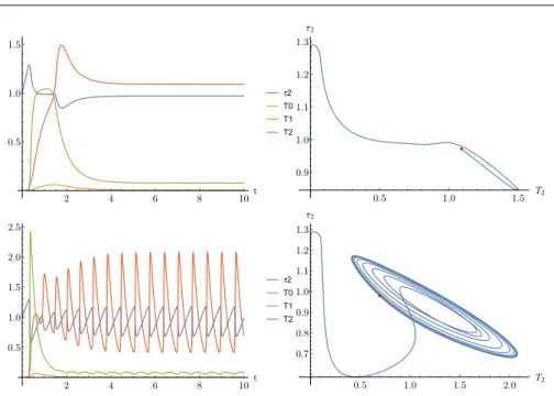
It has been shown [9, 10], that the 4D model of chip formation can exhibit periodic and even chaotic behaviour. Hopf–, Fold and period-doubling bifurcations with respect to the system parameterξ are shown in Fig. 2.
The bifurcation chart shows, that continuous chip formation can lose its stabil- ity, which leads to a fluctuation in the shear force (see the time domain simulation in Fig. 3). In practice, the saturation of the shear force close to zero value de- scribes the saw-tooth-like chip segmentation (as represented in our high speed camera measurements in Fig 4). The chaotic behaviour predicted by the model has already been presented in [15].
τ2
T0 T0
τ2 τ2
T0
ξ max τ2
0.95 1.3 0.35
0 1.3
0.16
0.02
0.7 0
0.7 1.3
0.3
F
F
H
H
PD PD
1.3 1.275 1.25 1.225 1.2 1.175 1.15
1.125
–2.5 0.0 2.5 5.0 7.5 10.0 12.5 15.0
Fig. 2 Bifurcations of chip formation model with respect to system parameterξ, published in [10]. Letters indicate, H: Hopf, F: Fold bifurcations and PD: Period doubling.
Parameter Value [unit]
k 0.008 [−]
Tw 300 [K]
E 200×10−9[Pa]
r 0.95 [−]
a 0.3 [−]
b 0.012 [−]
C 1 [−]
Φ 0.572 [rad]
δ 1.25×10⁻⁵ [m]
λ 16 [N/(msK)]
c ρ 500×7900
JK−1m−3
R 0.03 [m]
κ 0.05 [−]
ωn 3100 [rad/s]
L 7.5×10⁻⁴[m]
h0 1×10⁻³[m]
Ω 500 [rad/s]
p 1.012 [−]
s -0.012 [−]
Table 1 Parameter values in case of a realistic machining operation of steel workpiece. Ma- terial parameters are corresponding to austenitic (stainless) steel [9, 10].
3 Delay-differential equation of orthogonal turning
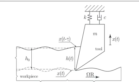
In this section, the traditional linear orthogonal turning model with surface regen- eration effect is presented (see Fig. 5) [1, 3, 23]. As in most of the cases there is a single dominant mode of the system, it is suitable to use a single degree of freedom mass-spring-damper model [1,2,11]. The governing equation of the system is given by:
mx(t) +¨ cx(t) +˙ k x(t) =k1w(h0−x(t) +x(t−τr)), (11)
2 4 6 8 10t 0.5
1.0 1.5
τ2 T0 T1 T2
0.5 1.0 1.5 T2
0.9 1.0 1.1 1.2 1.3 τ2
2 4 6 8 10t
0.5 1.0 1.5 2.0 2.5
τ2 T0 T1 T2
0.5 1.0 1.5 2.0 T2
0.7 0.8 0.9 1.0 1.1 1.2 1.3 τ2
Fig. 3 Time domain simulation of Eq. (1). Above: fixed point solution h0 = 0.001, Below:
periodic orbit solution h0 = 0.0018 - saw-tooth-like shear stress indicates similarly shaped chip. All other parameters are listed in Table 2. Shear stress and layer temperature values are dimensionless.
Fig. 4 High-speed camera picture of chip saw-tooth-like chip segmentation in case of milling.
where the parameters are: massm, dampingc, stiffnessk, cutting coefficient k1, chip width w, feed per revolution h0, time delay τ = 2π/Ω and spindle speed Ω. The right hand side of Eq. (11) expresses that the force acting on the tool is proportional to the actual chip thickness h(t) = h0−x(t) +x(t−τr), which is governed by the current tool position and the position in the previous revolution.
The number of parameters can be reduced by using their dimensionless variants respectively (dimensionless time ˆt = t ωn with natural angular frequencyωn = pk/m, damping ratio κ = c/2p
m/, k, dimensionless chip width Hw = w k1/k, dimensionless time delay ˆτ = 2πωn/Ω, dimensionless spindle speed ˆΩ =Ω/ωn).
k c
m
x ( t )
h ( t )
workpiece
ΩR
tool
x ( t -τ)
x ( t ) h
0Fig. 5 Simple mechanical model of orthogonal turning with surface regeneration effect.
0.5 1.0 1.5 2.0Ω ωn
-1.0 -0.5 0.0 0.5 1.0 HW
stable
unstable
Fig. 6 Stability chart of the DDE of turning, with respect toΩandHwparameters.
Rearranging Eq. (11), the time-delayed governing equation is written as follows [1]:
¨
x(ˆt) + 2κx(ˆ˙ t) +x(ˆt) =Hwh(ˆt), (12) h(ˆt) =h0−x(ˆt) +x(ˆt−τˆ). (13)
The stability boundaries of Eq. (12) are known analytically [1], and can be shown as the region below the so-called stability lobe structures in the stability chart (see Fig. 6).
In the subsequent section, the two above presented models are combined. The cutting coefficient in the turning model is determined based on the shear force in the chip formation model Eq. (1), while the chip thickness in the chip formation model is considered as a time dependent variable of the turning model Eq. (13).
k c m x ( t ) h ( t )
012 workpiece
ΩR
Φ
τ
2L chip
h
0 toolFig. 7 Model of shear zone in case of orthogonal turning with surface regeneration effect.
Numbers indicate shear layers.
4 Coupled system of turning and chip formation
Recall that the dimensionless time of the delay differential equation of the turning is ˆt = ωnt, but the 4D model of chip segmentation has a different time scale
˜t = t/K (see Eq. (7)). We transform the corresponding equations to match the dimensionless time of turning; substituting ˜t= ˆt/(K ωn) yields:
˙
τ2(ˆt) = (1−F1−F2)/(K ωn), (14)
τ1(ˆt) =p τ2(ˆt) +s,
T˙0(ˆt) = (ζ(T1(ˆt)−2T0(ˆt))−ξ T0(ˆt))/(K ωn),
T˙1(ˆt) = (η τ1(ˆt)F1−ζ(2T1(ˆt)−T2(ˆt)−T0(ˆt))−ξ(T1(ˆt)−T0(ˆt)))/(K ωn), T˙2(ˆt) = (η τ2(ˆt)F2−(ξ+ζ)(T2(ˆt)−T1(ˆt)))/(K ωn),
where the cutting speed isvc=Ω R.
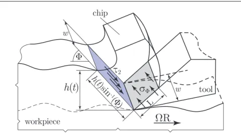
The two subsystems are fully coupled. The chip formation is influenced by the chip thickness h(ˆt) through the parameter K (see Eq. (7) as a parametric excitation. In our model we assume, that the cutting force is equivalent to the resultant of the shear stressτ2at the area of the principal shear planew h(ˆt)/sin(Φ) (see Fig. 8).
As the actual chip thickness is h(ˆt) = h0 −x(ˆt) +x(ˆt−τ), and the force acting on the tool isτ2τΦw h(ˆt)/sin(Φ), thex-directional component of the force is τ2τΦw h(ˆt). This couples the chip formation to the DDE of turning in the backwards direction and therefore the right hand side of Eq. (12) changes to:
¨
x(ˆt) + 2κx(ˆ˙ t) +x(ˆt) = w
kτ2(ˆt)τΦh(ˆt). (15) Note, that in our model, if we consider continuous chip formation with constant shear stress (τ2τΦ) then the cutting coefficient isk1=τ2τΦ in Eq. (11).
Introducing the dimensionless displacement ˆx= x/h0 and chip thickness ˆh(ˆt) = h(ˆt)w τh Φ
0k, Eq. (15) can be written as:
¨ˆ
x(ˆt) + 2κx(ˆ˙ˆ t) + ˆx(ˆt) =τ2(ˆt) ˆh(ˆt). (16)
h ( t )
workpiece ΩR Φ
τ
2L chip
w tool h (t
)si n
-1(Φ ) w
σ
ΦFig. 8 The shear planeand the area of chip-tool contact. The mechanical balance ofτ2
times the area of shear plane (w h(t)/sin(Φ)) and the corresponding component of the stress acting on the chip (σΦ) times the area of contact (w L) can be seen.
Note that by abuse of notations, the hat symbols ( ˆ) are discarded in the following sections.
The results of numerical simulations for the combined model are shown in Fig.
9. In the first case, the simulation shows continuous chip formation with almost constant shear force (yellow line) together with the transient oscillation of the tool (blue line). In the second case, the stability loss is only visible in the chip formation level, leading to large oscillation in the shear force at very high frequency, while the tool motion still shows a relatively slow transient oscillation.
Mathematically, this solution is unstable, however, from the practical point of view the tool vibration tends to very small amplitude oscillation creating negligible surface error and insignificant extra load on the cutting edge. It is clear that the tool motion with the relatively large time constant can not react to the very high frequency shear oscillation. Based on averaging in multi-scale methods [27], its average value is sufficient to be used during the simulation. The details of the averaging method are described next.
5 Averaging of the fast dynamics of chip formation
In the simplest form of the method of multiple scales, the variation of the chip thickness in Eq. (15) is considered to be quasi-static. During the simulations, first, the stationary solution of the shear plane must be determined as a function of the chip thickness, then its average can be used in Eq. (15) asτ2(h(t)).
If we consider the strong non-linearities in the chip formation model, then the bifurcations along the chip thickness parameterh0 must be described too.
By carrying out numerical simulations with realistic parameters, we obtained the following bifurcation diagrams. In Fig. 10, simulation results after sufficiently long numerical integration are shown, with the maximum, minimum and average ofτ2 values with respect toh0.
2 4 6 8 10t 0.5
1.0 1.5
x,τ2
x(t) τ2(t)
2 4 6 8 10t
0.5 1.0 1.5
x,τ2
x(t) τ2(t)
Fig. 9 Top to bottom:h0= 1.4×10−3,1.7×10−3[m], continuous and periodic chip formation.
The oscillation ofτ2is much faster due to the significant difference in the time scale of turning and chip formation. The shear stressτ2 values are dimensionless, the units of displacementx is [m/100].
It can be seen, that there is a critical chip thickness (h0,crit), which separates the fixed point solutions from the periodic solutions. In case of periodic chip forma- tion, the average value ofτ2is decreasing as the chip thickness increases due to the non-linearities. Note, that the stability charts are usually plotted as a function of cutting speedv=Ω Rand chip widthHw(see Fig 6.), so the influence ofΩis also examined. It is important to note that the critical chip thickness is not very sensi- tive to the cutting speed. In the example, these values wereh0,crit= 1.69×10⁻³[m]
andh0,crit= 1.75×10⁻³[m] for cutting speedsv= 6[m/s] andv= 30[m/s] respec- tively. Although these critical chip thickness values are unusually large, at the level of mathematical modelling these can be altered easily. In case of measurements one may found suitable material and cutting conditions to achieve considerably lower critical chip thicknesses.
We must note that as the shear stress reaches zero (τ2= 0), the chip forma- tion model loses its validity, because it does not deal with non-smooth case of discontinuous chip formation.
We can see in Fig. 10 that the average shear stress can be approximated as:
τ2(h) =
(τ2 h0≤hcrit
α hβ0+γ h0> hcrit
(17)
where α, β andγ are coefficients fitted to the simulated average ofτ2(h). Based on numerical simulations for largerh0 parameters and based on Fig. 10, we used the approximation γ = 0.4. The graph of the fitted functions in Fig. 11 has a very good correlation to the average shear stress values. The variation of the coefficients are plotted in Fig 12 with respect to the spindle speed. It is visible, that the cutting speed has negligible effect on the parameters. After the starting
0.0014 0.0016 0.0018 0.0020 0.0022 0.0024 0.0026 h0 0.2
0.4 0.6 0.8 1.0 1.2 1.4 τ2
Cutting speed v=6.[m/s]
0.0014 0.0016 0.0018 0.0020 0.0022 0.0024 0.0026 h0 0.2
0.4 0.6 0.8 1.0 1.2 1.4 τ2
Cutting speed v=30.[m/s]
Fig. 10 Minimum, maximum and average values ofτ2 in case of varyingh0and v. Legend:
Blueindicates average, redindicates minimum, purpleindicates maximum value ofτ2
in case of fixed point or periodic solution.
0.0015 0.0020 0.0025h0
0.5 0.6 0.7 0.8 0.9 1.0 τ2
Cutting speed v=6.[m/s]
h0,crit=1.81×10⁻³
0.0015 0.0020 0.0025h0
0.5 0.6 0.7 0.8 0.9 1.0 τ2
Cutting speed v=30.[m/s]
h0,crit=1.76×10⁻³
Fig. 11 Power function fitted on the average values ofτ2(h0). Left:v= 6[m/s], α= 1.164× 10⁻⁶, β=−2.085, γ= 0.4, R2= 0.0013. Right:v= 30[m/s], α= 1.81×10⁻⁶, β=−2.005, γ= 0.4, R2= 0.0014. Here the shear stress values are dimensionless.
point of the segmentation at bifurcation parameter h = h0,crit, the shear force tends to a decreased value with approximate decay rate of 0.7.
The function Eq. (17) can be substituted formally to Eq. (15):
¨
x(t) + 2κx(t) +˙ x(t) =τ2(h(t))h(t). (18) For the linear stability computation, first, the Taylor expansion of the right- hand-side according to the state variablesx(t) andx(t−τ) must be derived:
w τ2(h(ˆt))h(ˆt) =w τ2(h0−x(ˆt) +x(ˆt−τ)) (h0−x(ˆt) +x(ˆt−τ))u w τ2(h0)h0+w
τ2(h0) + ∂τ2
∂h0
h0
(−x(ˆt) +x(ˆt−τ)) + h.o.t. (19) In the linear stability analysis, the higher order terms and the static compo- nents can be eliminated (see [1]). The characteristic equation of the delay differ- ential equation of turning in case of averagedτ2can be written as:
(i ω)2+ 2κ(i ω) + 1 =Hw(τ2(h0) +h0τ20(h0)) (−1 +e−(i ω)τ). (20)
400 600 800 1000Ω 5. 10-7
1. 10-6 1.5 10-6 2. 10-6
400 600 800 1000Ω
-2.20 -2.15 -2.10 -2.05 -2.00 -1.95 β
400 600 800 1000Ω
0.00175 0.00180 0.00185 0.00190 h0,crit
400 600 800 1000Ω
0.00268 0.00270 0.00272 0.00274
h0,max
Fig. 12 The parameters of fitted functions and critical chip thickness / maximal chip thickness values [m] with respect toΩ[rad].
0.0005 0.0010 0.0015 0.0020 0.0025 0.0030 0.0035h
-0.4 -0.2 0.2 0.4 0.6 0.8 1.0
2+h 2,
Fig. 13 Plot ofτ2+h τ20 as appears in the characteristic polynomial.
In the range whereτ2(h0) is almost constant, the coefficient of the linear part would be w τ2(h0), which leads to the traditional turning model (see Section 2).
However, in the segmentation range, the derivative term of∂τ2/∂h0can radically decrease value of the already decreased value of average shear stress in the coeffi- cient, furthermore, it can shift it to a negative value, too (see. Fig 13).
The stability regions for Eq. (20) based on the D-subdivision method [1] were constructed using Multi-Dimensional Bisection Method [12]. For a fixed cutting speed, the stability boundary is plotted along the nominal chip thickness h0 for cases considering or neglecting the derivativeτ20(h) of the average (see Fig. 14).
The results show, that taking the proper derivative of the average shear force into account, the stable region further increases. The connection between the sud- den change in the stability limit and the coefficient on the right-hand-side can be clearly identified by comparing Fig. 13 and Fig 10. In the case at the critical value of h∗0 where the coefficients crosses the zeros line, theoretically, all the depth of cut at any spindle speed would be stable.
We also present the stability charts as a function of the spindle speed and the cutting depth for different chip width values, to show the vertical shift in the lobe structure. Fig. 15 shows the increasing stable domain in the range h0 ∈0. . . h∗0, while Fig. 16 presents the decreasing stable domain inh0∈h∗0. . .0.00275 [m].
0 0.5 1 1.5 2 2.5 3 h0 3.5 4 4.5×10⁻³⁵ 10-1
100
Hw
τ2(h) = const τ2(h) ≠ const, τ2’ = 0 τ2(h) ≠ const, τ2’(h) ≠ 0
0.001 0.002 0.003 0.004 0.005h
-0.4 -0.2 0.20.4 0.60.8 1.0
2+h 2,
Fig. 14 Stability regions of the coupled system. Blue line indicates the case, where the deriva- tive of the average with respect tohis neglected (τ2(h)≡τ2, τ20(h) = 0), green line indicates the case, when it is taken into account (τ20(h)6= 0).
Note, that this prediction is really sensitive to the fitted derivative of the average shear stress. We also found, that theτ2=α hβ0 function can fit reasonably well atβ≈ −1 value. However, in this case the termsτ2(h0) andh0∂τ2/∂h0would cancel each other. This would predict that the cutting process is always stable in case of segmented chip for any parameters.
The selected form of the fitted parameters can lead to a different prediction, but all of them lead to the same conclusion, that the segmentation can radically improve the stability properties.
6 Conclusions
In this work, we combined the surface regeneration model of the turning process with the mathematical modelling of chip formation. It is shown that the time scale of chip formation is several magnitudes smaller than the time scale of turn- ing, therefore the application of the simplest averaging method can be used to replace the dynamics of chip segmentation. Then the characteristic equation of the resulting system is analysed and its stability charts are presented.
0.5 1.0 1.5 2.0Ω ωn 0.5
1.0 1.5 2.0 HW
h0=0.0016978 h0=0.0017078 h0=0.0017978 h0=0.0018978 h0=0.0019579
Fig. 15 Stability lobes in case ofhcrit< h < h∗. See the increasing green domain in Fig. 14.
0.5 1.0 1.5 2.0Ω ωn
0.5 1.0 1.5 2.0 HW
h0=0.0021579 h0=0.0022579 h0=0.0023579 h0=0.0025579 h0=0.0027579
h0<hcrit
Fig. 16 Stability lobes in case ofh > h∗. See the decreasing green domain in Fig. 14. which tends to the blue region – meaning an increase in the stable domain compared to the continuous chip formation.
We found, that increasing the chip thickness decreases the average shear stress in the shear layer if oscillatory chip formation (chip segmentation) begins, and thus it increases the stability, shifting the lobe structure upwards, see Fig. 14.
This phenomenon could be utilized in case of flexible structures and hard-to-cut materials, where the chatter vibration is a great problem.
It is important to note that the chip formation model has a limited range of validity, once the shear stress in the shear layer reaches zero and the chip
breaks, the model is not applicable anymore (this is indicated by the vertical red border in Fig. 14). The chip formation model includes assumptions (for example the shear plane angle is considered constant) which makes experimental validation very complicated and valid only for that specific case, moreover these assumptions are usually not valid in the typical range of machining parameters in industrial applications.
The main goal of this work was to show the qualitative behaviour of the coupled model, that is, periodic chip formation can reduce the cutting force. This simplified model is a first step to show the importance of the critical range of chip formation and to highlight that modelling the shear layer could yield added value in the analytical process.
Acknowledgements The research leading to these results has received funding from the European Research Council under the European Union’s Seventh Framework Programme (FP7/2007-2013) ERC Advanced grant agreement No. 340889 and it was supported by the Hungarian Scientific Research Fund – OTKA PD-112983 and the Janos Bolyai Research Schol- arship of the Hungarian Academy of Sciences.
References
1. G. Stepan: Retarded dynamical systems: stability and characteristic functionsLongman Scientific & Technical, UK, ISBN: 0-582-03932-0 (1989)
2. S. A. Tobias, W. Fishwick: Theory of regenerative machine tool chatter.Engineer205(199–
203) 238–239 (1958)
3. S. A. Tobias: Machine Tool Vibration,Blackie and Son Ltd., Glasgow, (1965)
4. Y. Altintas: Manufacturing Automation: Metal Cutting Mechanics. Machine Tool Vibra- tions, and CNC Design,Cambridge university press(2012)
5. J. Munoa, X. Beudaert, Z. Dombovari, Y. Altintas, E. Budak, C. Brecher, G. Stepan:
Chatter suppression techniques in metal cutting,CIRP Annals-Manufacturing Technology 65 (2), 785-808
6. J. Tlusty, M. Polacek: The stability of the machine tool against self-exited vibration in machining.Proceedings of the International Research in Production Engineering Conference, ASME Press, Pittsburgh, 465–474 (1963)
7. J. Tlusty: Analysis of the state of research in cutting dynamics,CIRP Annals27583–589 (1978)
8. Z. P´almai, Chaotic phenomena induced by the fast plastic deformation of metals during cutting,ASME Journal of Applied Mechanics73: 240—245 (2006)
9. Z. P´almai, G. Csern´ak: Chip formation as an oscillator during the turning process,Journal of Sound and Vibration326(3-5): 809–820 (2009)
10. G. Csern´ak, Z. P´almai: Exploration of the chaotic phenomena induced by fast plastic deformation of metals,The International Journal of Advanced Manufacturing Technology 40(3): 270–276 (2009)
11. Trent, E. M., Wright, P. K.: Metal Cutting,Butterworth-HeinemannISBN 978-0-750- 67069-2(2000)
12. D. Bachrathy, G. Stepan: Bisection method in higher dimensions and the efficiency number, Periodica Polytechnica, Mechanical Engineering56(2): 81–86. (2012)
13. H. T. Sykora, D. Bachrathy, G. Stepan: A theoretical investigation of the effect of the stochasticity in the material properties on the chatter detection during turningProceedings of the ASME 2017 Conference on Mechanical Vibration and NoiseAugust 6-9, (2017) 14. T. G. Moln´ar, T. Insperger, D. Bachrathy, G. Stepan: Extension of Process Damping
to Milling with Low Radial Immersion,International Journal of Advanced Manufacturing Technology89:2545—2556. (2017)
15. R. S. Pawade, S. S.Joshi, Mechanism of Chip Formation in High-Speed Turning of Inconel 718,Machining Science and Technology15(1):132–152. (2011)
16. D. Hajdu, T. Insperger, G. Stepan: Robust stability analysis of machining operations, International Journal of Advanced Manufacturing Technology88(1):45–54 (2017)
17. Y. Altintas, M. Eynian, H. Onozuka: Identification of dynamic cutting force coefficients and chatter stability with process damping,CIRP Ann Manuf Techn57(1):371–374 (2008) 18. E. Budak, L.T. Tunc: Identification and modeling of process damping in turning and
milling using a new approach,CIRP Ann - Manuf Techn59(1):403–408 (2010)
19. G. Stepan, Z. Dombovari, J. Munoa: Identification of cutting force characteristics based on chatter experiments,CIRP Annals-Manufacturing Technology60(1):113–116 (2011) 20. D. Bachrathy, G. Stepan: Bistable parameter region caused by velocity dependent chip
thickness in milling process,12th CIRP Conference on Modelling of Machining Operations.
San Sebastian, Spain978-84-608-0866-4:867–871 (2009)
21. E. ¨Ozl¨u, E. Budak, Analytical Modeling of Chatter Stability in Turning and Boring Op- erations—Part II: Experimental Verification,Journal of Manufacturing Science and Engi- neering129(2007)
22. Z. Dombovari, J. Munoa, R. Kuske, G. Stepan: Non-smooth torus to identify domain of attraction of stable milling processes9th European Nonlinear Dynamics Conference (ENOC 2017), Budapest, Hungary (2017)
23. M. Eynian, Y. Altintas: Chatter stability of general turning operations with process damp- ing,Journal of Manufacturing Science and Engineering131(4):041005. (2009)
24. Budak E, Tunc LT (2010) Identification and modeling of process damping in turning and milling using a new approach. CIRP Ann - Manuf. Techn. 59(1):403–408
25. Cedergren, S., Frangoudis, C., Archenti, A. et al.: Influence of work material microstructure on vibrations when machining cast Ti-6Al-4V,Int J Adv Manuf Technol84: 2277. (2016) 26. Bachrathy, D. (2015). Robust stability limit of delayed dynamical systems. Periodica Poly-
technica. Engineering. Mechanical Engineering, 59(2), 74.
27. G. A. Pavliotis, A. M. Stuart: Multiscale Methods: Averaging and Homogenization, SpringerISBN 978-0-387-73828-4(2008)
![Fig. 2 Bifurcations of chip formation model with respect to system parameter ξ, published in [10]](https://thumb-eu.123doks.com/thumbv2/9dokorg/1397330.116699/5.892.141.630.112.427/fig-bifurcations-chip-formation-model-respect-parameter-published.webp)

![Fig. 9 Top to bottom: h 0 = 1.4×10 −3 , 1.7×10 −3 [m], continuous and periodic chip formation.](https://thumb-eu.123doks.com/thumbv2/9dokorg/1397330.116699/10.892.111.554.111.429/fig-h-m-continuous-periodic-chip-formation.webp)

![Fig. 12 The parameters of fitted functions and critical chip thickness / maximal chip thickness values [m] with respect to Ω [rad].](https://thumb-eu.123doks.com/thumbv2/9dokorg/1397330.116699/12.892.111.629.113.317/parameters-fitted-functions-critical-thickness-maximal-thickness-respect.webp)

