Doctoral School of Chemical Engineering and Material Sciences University of Pannonia
M
ODIFICATION AND CHARACTERIZATION OF ADSORBENT MATERIALS AND CNTS FOR OIL SPILL CLEANUP FROM WATERWritten by
Nour Abdullah Ameen Aljammal
Supervisor
Dr. Juzsakova Tatjána, Associate professor
Submitted in partial fulfilment of the requirements for the degree of Doctoral School of Chemical Engineering and Material Sciences
Veszprém, Hungary 2019
DOI:10.18136/PE.2019.729
Modification and Characterization of Adsorbent Materials and CNTs for Oil Spill Cleanup from Water
Thesis for obtaining a Ph.D. degree in
The Doctoral School of Chemical Engineering and Material Sciences of the University of Pannonia.
Institute of Environmental Engineering Prepared by: Nour Abdullah Ameen Aljammal
Supervisor: Dr. Juzsakova Tatjána, Associate professor
Propose acceptance (yes / no) ...
Associate prof. Dr. Juzsakova Tatjána
The candidate has achieved ... % in the comprehensive exam, Veszprém
...
Dr.
(Chairman of the Examination Committee)
As a reviewer, I propose acceptance of the thesis:
Name of reviewer: ... yes / no
...
(Signature)
Name of reviewer: ... yes / no
...
(Signature) The candidate has achieved... % at the public discussion
Veszprém, 2019. ...
...
(President of UCDH)
i
Modification and characterization of adsorbent materials and CNTs for oil spill cleanup from water
by
Nour Abdullah Ameen Aljammal
Supervisor:
Associate prof. Dr. Juzsakova Tatjána
Abstract
In this dissertation, two methods were implemented for expanding the environmental applications of two unique materials; namely the Jordanian zeolitic tuff (RZT) and multiwalled carbon nanotubes (MWCNTs). From their discovery until today, these materials have been widely investigated for several applications. While much work has been devoted to investigating the scope of their possible applications as adsorbents, enhancing their properties to be tailored to specific purposes, as oil adsorbents for oil spills remediation are still needed for the full potential of this class of materials.
The acquired knowledge of these materials and their characteristics have been essential for their application as adsorbents. The application of solid adsorbents for oil spills remediation has gained attention in recent times. This is due to the potential of this technology to minimize the danger of surface water spill or subsurface leakage of pe- troleum/petroleum derivatives. However, this requires the development of novel solid adsorbent materials with significant selectivity, large adsorption capacity, and fast ad- sorption coupled with excellent mechanical strength and the ability of regeneration.
This work aimed to develop advanced oil adsorbents for the removal of hydrocarbons from surface water. Chemical modifications of RZT and MWCNTs are manifested either in the backbone composing the underlying structure or in the functionalities ex- posed to the pore space and outer surface of the raw materials. Both approaches, mi- croemulsification of MWCNTs and dealumination of RZT, are investigated in this dissertation. As the hydrophobic properties are the primary determinants of effective oil adsorbents, the hydrophobicity of RZT was modified via dealumination by single acidic treatment (TZT). Thus, the acid treatments markedly changed the composition and surface area of RZT so that the intrinsic properties of the RZT microporous struc- ture come into effect. Further treatment of the dealuminated zeolitic tuff was achieved by microemulsion technique (µETZT). The microemulsion method was implemented to modify the surface structure of MWCNTs by attaching a hydrocarbon tail on its surface. Activated carbon was used as benchmark adsorbent for performance compar- ison.
The structural and surface chemistry properties of the prepared adsorbents were stud- ied by different surface analytical techniques such as Brunauer-Emmett-Teller (BET) method, thermogravimetric analysis (TG), X-Ray diffraction (XRD), Raman-spectros- copy, microstructure and morphology using scanning electron microscopy (SEM),
ii
thermogravimetric analysis (TG) and Fourier-transform infrared spectroscopy (FTIR).
The hydrocarbon removal efficiencies of the unmodified and functionalized sorbents were examined by using total organic carbon analyzer (TOC), gas chromatography (GC), and UV-Visible spectroscopy (UV-Vis) techniques. Different model hydrocar- bon compounds were used for this investigation.
The experimental results revealed that microemulsion as a type of surface functional- ization solved one main issue regarding MWCNTs functionalization as it proved to be beneficial for producing hydrophobic adsorbent with keeping the high crystallinity and uniformity of MWCNTs surface and without the need of additional functionalization and substitution steps to attach hydrocarbon side chains. Using kerosene as a hydro- carbon model compound, compared with raw MWCNTs, the maximum adsorption ca- pacity of µMWCNTs increased by 63.5%. The adsorption capacity over zeolite-based adsorbents, enhanced by three- and four-fold for TZT and µETZT, respectively. Ad- ditionally, the outcomes indicated that the octane adsorption capacities of µ ETZT and µEMWCNTs reached up to 1.73 g/g and 6.07 g/g, respectively.
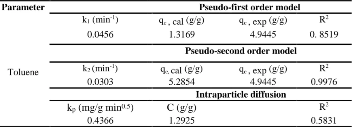
The kinetics experiments indicated that the capacities of µEMWCNTs, TZT, µETZT for the uptake of hydrocarbon increased when the sorption time increased. Pseudo-first order, pseudo-second-order, and intraparticle diffusion were examined for kinetic studies of toluene adsorption over the synthesized adsorbents. It was concluded that the kinetic data could be well described by the pseudo-second-order model with a high correlation coefficient.
iii
Table of Contents
Abstract ... i
List of Tables ...v
List of Figures ... vi
List of Abbreviations ... viii
Acknowledgments ... xi
Chapter 1: Introduction ... 1
1.1 Background ...1
1.2 Context And Purposes ...3
1.3 Significance, Scope, and Definitions ...5
Chapter 2: Literature Review ... 6
2.1 Historical Background ...6
2.2 Remediation technologies ...8
2.3 Adsorption ...10
Carbon nanotube-based adsorbents ...15
Zeolite based adsorbents...19
2.3.2.1 "Low" and "intermediate" silica zeolite adsorbent ...21
2.3.2.2 "High" silica zeolite ...22
Chapter 3: Research Design ... 25
3.1 Methodology ...25
3.2 Materials ...26
Carbon nanotubes based adsorbents ...26
Zeolite based adsorbents...26
Commercial adsorbents ...27
Chemicals and methodology ...27
3.2.4.1 Dealumination of zeolitic tuff ...27
3.2.4.2 Microemulsion, chemicals, and preparation ...27
3.3 Characterization of the adsorbents ...28
X-ray diffraction (XRD) measurements ...28
X-ray fluorescence (XRF) measurements ...29
Fourier transform infrared spectrometry (FT-IR) measurements ...29
Raman spectroscopy measurements ...29
Brunauer–Emmett–Teller (BET) measurements ...30
Scanning electron microscopy (SEM) and energy dispersive X-ray (EDX) measurements ...30
Thermogravimetric analysis (TGA) measurements ...31
3.4 oil adsorption tests ...31
Feedstock solution preparations and adsorption tests ...31
3.4.2.1 Adsorption protocol of kerosene - water solution ...32
3.4.3.1 Adsorption of pure hydrocarbon - water solutions ...33
Instruments and protocols used for the analysis of hydrocarbon concentration measurements in water ...33
3.4.4.1 Classical Westinghouse method of adsorption ...34
iv
3.4.4.2 Protocol for samples analysis via total organic carbon analyzer (TOC) ...34
3.4.4.3 Protocol for samples analysis via UV-Vis spectrophotometric ...34
3.4.4.4 Protocol for samples analysis via gas chromatography (GC) ...35
Chapter 4: Results of MWCNTs based adsorbents ... 37
4.1 Characterization results of carbon-based adsoebents ...37
Results of the SEM and TEM investigations ...37
Results of the morphological measurements ...40
Results of the XRD investigations ...43
Thermoanalytical investigations ...44
Raman spectroscopic measurements ...46
FT-IR spectra measurements ...47
4.2 Adsorption Test results ...49
Performance evaluation of µEMWCNTs by classical Westinghouse method ...49
Performance evaluation of µEMWCNTs via by TOC analysis ...50
Performance evaluation of µEMWCNTs by GC results ...51
Performance evaluation of µEMWCNTs by UV-Vis spectrophotometric ...52
Kinetic studies over µEMWCNTs ...53
Chapter 5: Discussion of the results obtained over MWCNTs ... 59
Chapter 6: Results of zeolite-based adsorbents ... 63
6.1 Characterization results of zeolite-based adsorbents ...63
Results of SEM and EDX investigations ...63
Results of the morphological measurements ...67
Results of X-ray diffraction measurements ...70
Results of FT-IR spectroscopy measurements ...72
Results of X-ray fluorescence (XRF) measurements ...75
Results of Thermoanalytical investigations ...75
6.2 Adsorption tests ...79
Performance evaluation of TZT and µETZT by classical Westinghouse method ...79
Performance evaluation of TZT and µETZT by TOC results ...80
Performance evaluation of TZT and µETZT by GC results ...83
Adsorption kinetic experiments over TZT ...84
Chapter 7: Discussion of zeolite-based adsorbents results ... 87
Chapter 8: Conclusions ... 92
Chapter 9: New scientific findings / theses ... 99
9.1 Carbon nanotube-based adsorbent ...99
9.2 Zeolite-based adsorbent ...100
Bibliography ... 103
Appendices ... 117
B.1 µemwcnts microemulsion mass calculations ...118
B.1 µeTZT microemulsion mass calculations...119
v
List of Tables
Table 1: The 13 largest oil spills in history ...6
Table 2: Oil cleanup techniques ...9
Table 3: Adsorbents types and their properties ...14
Table 4. Properties of Tell Hassan RZT ...26
Table 5: Summary of the performed batch experiments ...32
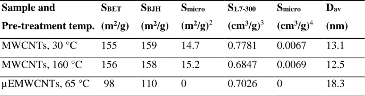
Table 6: Nitrogen adsorption results of samples MWCNTs and µEMWCNTs ...40
Table 7: Mass loss data of samples MWCNTs and µEMWCNTs during thermoanalytical studies ...46
Table 8: Sorption of different hydrocarbons over samples MWCNTs and µEMWCNTs (g adsorbate/g adsorbent) ...49
Table 9: n-C11H24 removal efficiency of MWCNTs determined by TOC ...50
Table 10: Undecane and kerosene removal efficiencies over MWCNTs, µEMWCNTs, and commercial activated carbon sorbents ...51
Table 11: UV-Visible spectrophotometric results over samples MWCNTs and µEMWCNTs form the removal of toluene ...53
Table 12: Kinetic parameters of the pseudo 1st order, pseudo 2nd, and intra-particle diffusion models for toluene adsorption by µEMWCNTs ...55
Table 13: SEM-EDX results of zeolite-based adsorbents; composition and elemental distribution in the near-surface layer ...65
Table 14: Characterization with BET for RZT, TZT, µETZT and commercially activated carbon adsorbents ...67
Table 15: The elemental analysis of RZT, TZT and µETZT samples using XRF technique...78
Table 16: Data from thermo-analytical measurements of zeolitic tuff samples ...78
Table 17: The sorption of kerosene and different hydrocarbon compounds on RZT, TZT and µETZT according to Westinghouse method ...80
Table 18: GC analysis data for kerosene adsorption from water over raw, treated and microemulsified zeolitic tuff and activated carbons ...84
Table 19: Adsorption capacities of hydrocarbons over zeolites adsorbents ...84
Table 20: Kinetic parameters of pseudo 2nd models for n-octane and dodecane adsorption over TZT ...85
Table 21: The change in toluene removal efficiency of over µEMWCNTs in the function of contact time ...117
Table 22: The change in toluene removal efficiency of over MWCNTs in the function of contact time ...117
vi
List of Figures
Figure 1: Location of spills >7 tonnes from 1970 to 2018 ...7
Figure 2: Illustration of the adsorption process in which atoms, ions, or molecules are adhering to the surface of the adsorbent ...11
Figure 3: Illustration of the absorption process, in which atoms, ions, or molecules entering the volume of the absorbing substance ...11
Figure 4: Modes of CNTs functionalization ...17
Figure 5: Surface functionalization of CNTs ...18
Figure 6: Framework and extra- framework in zeolite ...20
Figure 7: Dealumination hydrolysis reactions (left) and desilication hydrolysis reactions (right) ...24
Figure 8: The transmission electron microscopic (TEM) record of the MWCNTs ...37
Figure 9: The scanning electron microscopic (SEM) record of the MWCNTs (by courtesy of the MWCNTs manufacturer) ...38
Figure 10: The scanning electron microscopic (SEM) record of the MWCNTs ...38
Figure 11: The scanning electron microscopic (SEM) record of the (a) Raw MWCNTs, (b) µEMWCNTs at magnification: x 20.000 and (c) Raw MWCNTs, (d) µEMWCNTs at magnification: x 40.000 ...39
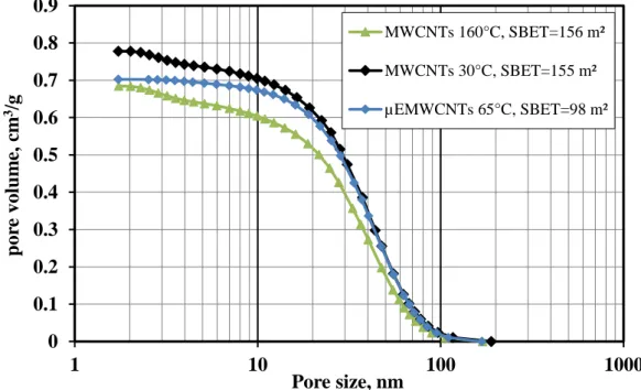
Figure 12: Cumulative mesoporous volume distribution of MWCNTs ...41
Figure 13: Logarithmic pore volume distribution of MWCNTs calculated based on the BJH theory ...42
Figure 14: Adsorption and desorption isotherms of MWCNTs ...42
Figure 15: XRD patterns of MWCNTs and µEMWCNTs samples ...43
Figure 16: TG and DTG curves of samples MWCNTs and µEMWCNTs ...45
Figure 17: The Raman spectra of samples MWCNTs and µEMWCNTs ...47
Figure 18. Fourier transform infrared spectra of samples fresh µEMWCNTs and spent µEMWCNTs. ...48
Figure 19: UV-Vis spectrophotometric results for MWCNTs and µEMWCNTs ...52
Figure 20: The change in toluene removal efficiency of over µEMWCNTs and MWCNTs in the function of contact time ...54
Figure 21: Adsorption kinetics of toluene over µEMWCNTs, pseudo 1st order plot ...56
Figure 22: Adsorption kinetics of toluene over µEMWCNTs, pseudo 2nd order plot ...56
Figure 23: Adsorption kinetics of toluene over µEMWCNTs, intraparticle diffusion plot ...57
Figure 24: Kinetic analysis of temperature effect (µEMWCNTs = 10 mg/in 100 ml toluene-water solution 500 mg C/L) ...58
Figure 25: Hypothetical phase regions of microemulsion systems (Malik et al., 2012) ...59
Figure 26: Illustration for µEMWCNTs and the droplet of the microemulsion ...60
vii Figure 27: The mechanism of the surface functionalization and sorption of toluene over
µMWCNTs ...61 Figure 28: SEM images of raw (a) zeolitic tuff surface and (b) acid-treated (magnifications
300x) ...64 Figure 29: EDX results of RZT and TZT ...65 Figure 30: The scanning electron microscopic (SEM) record of the (a) RZT, (b) µTZT
at magnification: x 200 and (c) RZT, (d) µETZT at magnification: x 20.000...66 Figure 31: Volume of N2 adsorption isotherm versus relative pressure for RZT, TZT,
and spent TZT...69 Figure 32: Cumulative pore volume (BJH -calculation method) for RZT, TZT and spent
TZT ...70 Figure 33: XRD patterns for RZT, TZT, and µETZT where P-phillipsite, Ch-chabazite,
F-Faujasite; A-anorthite, F-forsterite; D-diopside; C-calcite; H-hematite; Q- quartz; Ha-halite ...71 Figure 34: FT-IR spectra of zeolitic tuff samples: A - ν(O–H) and ν(C–H) stretching
region (4000-2700 cm-1); B - δ(O-H), ν(Si-O/Al-O) deformation and stretching region (1800–400 cm-1)...73 Figure 35: TG, DTG and DTA curves for zeolitic tuff samples: (a) RZT; (b) TZT; (c)
µETZT ...77 Figure 36: The change in percentage n-octane removal of over RZT, TZT, µETZT, and
activated carbon ...81 Figure 37: Effect of adsorption time on the adsorption capacity of TZT using n-octane
as a model hydrocarbon. (Dosage of material= 0.5 g, Ci n-octane = 470 mg C/L, temperature= 25 oC) ...85 Figure 38: Effect of adsorption time on the adsorption capacity of TZT using undecane
as a model hydrocarbon. (Dosage of material= 0.5 g, Ci n- dodecane = 470 mg C /L, temperature= 25 oC) ...86 Figure 39: Schematic depiction of zeolite crystals with hydrophobic (red) or hydrophilic
(blue) domains located at external crystal surfaces (solid lines) or internal pore surfaces (dashed lines) ...88 Figure 40: Dealumination process of zeolites ...89 Figure 41: Schematic showing the interaction of the surfactant on the surface of the
µETZT ...91
viii
List of Abbreviations
List of Symbols
C Intraparticle diffusion constant g/g
Co Concentrations of adsorbate at the initial time mg/l
Ct Concentrations of adsorbate at time t mg/l
Cf Concentrations of adsorbate at final time t mg/l
Dav Average pore diameter nm
k1 Adsorption rate constant of the first-order model 1/min
k2 Rate constant of second-order model g/g. min
kp Intraparticle diffusion rate constant g/g.min0.5
Mo The weight of the sorbent g
Mp Mass of adsorbed hydrocarbon g
R2 The values of the residual standard error -
RE Removal efficiency %
qe Equilibrium Adsorption capacity g/g
qt Adsorption capacity at time t g/g
S1.7-300 Pore volume having a diameter between 1.7 and 300 nm cm3/g
SBET Specific surface area m2/g
SBJH Surface area for pores m2/g
Smicro The specific surface area of micropores (< 2 nm) m2/g
Vmicro Volume respectively of micropores (< 2 nm) cm3/g
λ Absorbance wavelength nm
List of abbreviations and acronyms
µEMWCNTs Microemulsified multi-walled carbon nanotubes µETZT Microemulsified zeolitic tuff
BET Brunauer-Emmett-Teller surface area determination method
BJH Barret–Joyner–Halenda pore size distribution determination method BTEX Benzene, toluene, ethylbenzene and xylene
DTA Differential thermal analysis
EDX Energy Dispersive x-ray elemental analysis FT-IR Fourier transform Infrared Spectrometry
ITOPF International Tanker Owners Pollution Federation Limited IZA International Zeolite Association
MWCNTs Multi-walled carbon nanotubes PTFE Poly(tetrafluoroethylene) RBM Radial breathing mode
ix
RE Removal Efficiency
RZT Raw zeolitic tuff
S Sorption
SAS Secondary-alkane-sulfonate SEM Scanning Electron Microscopy SLES Sodium-lauryl-ether-sulfate TDS Total dissolved solids TGA Thermogravimetric analysis
TOC Total Organic Carbon
TZT Treated zeolitic tuff
V Volume
W Mass of adsorbent
XRF X-ray diffraction
x
Statement of Original Authorship
The work contained in this thesis has not been previously submitted to meet require- ments for an award at this or any other higher education institution. To the best of my knowledge and belief, the thesis contains no material previously published or written by another person except where due reference is made.
Signature: _________________________
Date: _________________________
xi
Acknowledgments
And for the pleasant task of acknowledging those who assisted in this thesis. No work such as this can be contemplated without the promise of advice and assistance from one’s friends and colleagues, and I must first express my very deep sense of gratitude to my supervisor Dr. Juzsakova Tatjána and to Prof. Rédey Á kos, who more than an- yone else has been responsible for this thesis coming to completion. This work owes much to Prof. Rédey Á kos, the moment we first talked about it in 2016, he seemed to have guessed my whole purpose, and ever since, he has never ceased to help its pursuit.
I am most grateful for their unfailing support and help in a variety of ways.
I am also indebted to a number of my friends who have supported me all over the way.
Dr. Balázs Zsirka and Dr. Viktor Sebestyén deserve special thanks for their extensive pieces of advice. One of the most pleasing aspects of my work has been the speed with which colleagues worldwide, some of whom I have never met, have promptly sup- ported me, Prof. Igor Cretescu.
I acknowledge the financial support of this work through GINOP-2.3.2-15-2016- 00016 project: Excellence of strategic R&D workshops: Development of modular, mo- bile water treatment systems and wastewater treatment technologies based on the Uni- versity of Pannonia to enhance growing dynamic export of Hungary.
Finally, I want to express my appreciation for one person who unhesitatingly shared with me the details of this journey and sustained year after year the stresses radiating from me as the center of this activity, my Father. I also wish to thank my family for their patience during the trying ordeal of thesis preparation, a word of apology for the many occasions on which I was forced to neglect them while working on this thesis.
1
Chapter 1: Introduction
This chapter outlines the background of oil spills and their remediation technique in section 1.1. The context and purposes of this research are elaborated in section 1.2.
Section 1.3describes the significance and scope of this research and provides defini- tions of terms used.
1.1 BACKGROUND
Oil spillage has always been seen as ubiquitous and central in several areas of the conventional and contemporary environment’s scientific interest. The world witnessed several oil spills accidents, which resulted in massive contamination of the water bod- ies including the oceans, seas, lakes, and rivers (Aguilera et al., 2010; Chang et al., 2014; Peterson et al., 2003; Toyoda and Inagaki, 2000).
Oil spills are considered serious environmental catastrophes since they result in both immediate and long-term ecological and environmental damages (Peterson et al., 2003; Toyoda and Inagaki, 2000). Moreover, oil contamination of the soils and geo- logical layers threaten the underground water reservoirs. Since the oil products contain toxic/phytotoxic compounds, in particular, aromatic hydrocarbons, heteroatom- containing compounds and occasionally heavy metals such as, e.g., arsenic, the con- tamination of the waters exhibit high risks for the healthy and safe water supply (Ahmaruzzaman, 2011; Annunciado et al., 2005). As a consequence of the massive oil spill of about 210 million gallons in the Gulf of Mexico on 22nd April 2010 caused by the explosion at the Deep-water Horizon oil rig, both the accidental and deliberate releases of oil during production, transportation, and storage became a worldwide concern.
Different types of oils and petroleum fractions exhibit different properties; therefore, the environment and ecosystems are influenced in several ways (Liu and Kujawinski, 2015). The light oils and light petroleum fractions present major hazards as those can ignite or explode. Moreover, many light petroleum fractions, such as gasoline, kerosene, and diesel, are considered to have toxic potential, as well. The light
2
petroleum fractions can kill animals or plants after contact, and they are dangerous to human beings who breathe their vapours. The destructive effects of spilled oil on ecosystems and the long-term influence of environmental pollution alert for urgent solutions to improve the existed technologies for oil pollution cleanup.
Due to the recent increase in oil contamination of water, the repercussions of oil expo- sure on the environment have become an environmental concern. Thus, the treatment of oil-contaminated water is of top priority for many organizations (EPA, 2018, 2015;
WHO, 2008). One of the most challenging decisions that oil spill responders face during a spill is evaluating the trade-offs accompanying with choosing the most appropriate remediation technique. Therefore, the type of spilled oil along with the propagation speed of the oil on the water surface influenced by water temperature, and weathering processes such as; atmospheric temperature, wind, and flow directions are very significant aspects of guiding the companies and authorities to decide on the pre- eminent remediation techniques. For example, burning as a remediation technique can be used for the spilled oil with a high percentage of volatile compounds, while this method must be avoided if the spilled liquid is heavy oil, which burns poorly.
On one hand, every effort should be made to prevent spilled oil from spreading, as removing oil from sand, rocks, and vegetation is difficult and costly. However, if it happened, then a combination of several remediation techniques must be used as a first-class and second-class intervention. Regardless of the effectiveness of the modern technologies used as a practical approach for petrochemical wastewater treatment (Guodong et al., 2015; Sepehri and Sarrafzadeh, 2018), the researchers keep looking for an efficient, environmentally friendly and cost-effective technology for oil spill remediation over large areas such as adsorption.
In some cases, primary remediation technique such as manual removal via shovels and rakes can be used to remove the majority of heavy oil spilled or bituminous cuts as main remediation technique as this method has the advantage of minimizing waste generation but is labour intensive and relatively slow; thus, additional remediation technique is needed, as adsorption. It is, however, not always easy to decide what is the best combination for efficient spill removal. Nevertheless, it is believed that ad- sorption can play a vital part in the remedial-actions combination. Adsorption can be used as (i) primary oil recovery for very small and limited oil spills in sea and spills
3
from tankers. Or (ii) as an integrated technique for another remediation process in which the sorbent can be used to clean up the final traces of oil spills on water surfaces or land (Fingas, 2016). Several factors influence the selection of appropriate adsorbents such as availability, cost, safe use, and regeneration of the adsorbent materials. Many other parameters governed by the structure of the adsorbents play a vital role in the cleaning process such as hydrophobicity (oleophilic properties), porosity, suitable pore size, and surface area. Adsorbents with the high surface area have proved to be highly efficient and versatile materials for oil removal from the water surface. Nonetheless, a small number of materials meet all these requirements for selectivity, adsorption capacity, adsorption rate, and recyclation.
1.2 CONTEXT AND PURPOSES
Adsorption is believed to be a simple, cheap, and effective technique for the removal of hydrocarbons from emulsified water. However, the synthesis of adsorbents with superior oil sorption performance remains a great challenge. Moreover and as men- tioned earlier that despite the many exciting and compelling recent developments on CNTs and clay minerals applications as adsorbents, sorption on a large scale is still in an immature phase. There is already a very considerable literature on the application of adsorbents for hydrocarbons removal from oil-contaminated water, and no doubt, its growth is set to continue. Hence, the novelty of this study arises from the possible enhancement of hydrophobic properties for natural zeolites and CNTs materials easily and cost-effectively. Since the rapid development in sorbent materials and innovative cyclic adsorption processes has become an essential separation process in many envi- ronmental applications. At the outset, there would seem to be two different classes of question demanding attention, to justify the novelty of this work, on one hand, the reason behind selection above addressed adsorbents, and discern what kind of pre- treatment and functionalization may enhance their adsorptive properties.
The reasoning behind the selection of these two adsorbents stemmed solely from the outcome of a deep literature review of the existing oil adsorbents. Both adsorbents the multi-walled carbon nanotubes MWCNTs and natural zeolite have a unique structure and high specific surface area in addition to exceptional mechanical properties, rapid
4
sorption rates, high sorption capacity, and engineered surface chemistry. All this struc- tural diversity has underscored its potential in water remediation processes, although fewer examples exist.
CNTs as a new class of carbon-based adsorbents as it believed to hold remarkable positions in adsorptive materials for various reasons. For one thing, they provide chem- ically inert surfaces for physical adsorption, as their high specific surface areas meas- ure up to those of activated carbons (ACs).
Clay mineral as zeolitic tuff was selected as one of the available outstanding porous material with crystalline aluminosilicate structure with several microporous and cavi- ties of numerous sizes at regular intervals. Much interest has been shown for zeolites due to the controllable level of aluminium/silicon, and it is potential for numerous applications such as synthesis of the water softener. Zeolites’ sieving properties, func- tioning at the molecular level, and their exceptional chemical, thermal and hydrother- mal stability advocate that these porous materials may have technological potential as adsorbents in separation and purification processes in aqueous media. Furthermore, the availability of natural zeolites in many countries such as China, Jordan, Turkey, the United States, with considerable deposits, provides low-cost treatment such as the ion-exchange process. According to the U.S. Geological survey in 2019, the world's annual production of natural zeolite approximates 1,100,000 tons (U.S. Geological Survey, 2019). Further significant developments via chemical modification on zeolites and CNTs can enhance their adsorptive properties. Based on the literature review, there is an incentive to develop cost-effective and high performance natural and carbon- based adsorbents for second stage removal of hydrocarbon from water (after mechan- ical treatment). Knowledge gaps for this purpose were identified as follows (i) natural and carbon-based adsorbents have not been adequately developed and characterized for removal of hydrocarbon from water and (ii) implications of this work concerning physico-chemical properties of adsorbents are not extensively elucidated.
It is noteworthy that at the time of compiling this thesis, no book had been published to date, which proposes an easy and cost-effective way for the preparation and charac- terization of highly hydrophobic adsorbents. Therefore, this work has attempted to provide a detailed account of the preparation of highly hydrophobic adsorbents with a particular emphasis on the microemulsion of CNTs and dealumination of zeolitic tuff
5
as a state of the art modification techniques. To this end, the thesis has been sub-di- vided into nice chapters.
1.3 SIGNIFICANCE, SCOPE, AND DEFINITIONS
This investigation aims to develop an effective, low cost, flexible, sustainable, and environmentally friendly adsorbent as a potential method for adsorbing hydrocarbons from oil-contaminated water. The efficiency of both adsorbents for the removal of several model hydrocarbons was further investigated by studying further physico- chemical characteristics of the proposed adsorbents. The main parameters that influ- ence hydrocarbon’s adsorption abilities are considered; thus, the main aims of the the- sis can be given as follows:
To modify the surface of both adsorbents to increase the hydrophobic prop- erties,
To characterize both raw and modified forms, to determine whether the se- lected treatment improves its selectivity properties or adsorption capacity,
Sorption models are to be studied to determine the exact mechanism of the sorption,
To identify the factors that affect the performance of adsorbents and affect the rate of adsorption,
To determine the applicability of several kinetic models, pseudo-first-order, second-order and intraparticle diffusion isotherms and to estimate the pa- rameters characterizing the performance of the batch process
6
Chapter 2: Literature Review
This chapter begins with a historical background for oil spills (section 2.1) and reviews literature on the following topics: remediation techniques (section 2.2); particular fo- cus on adsorption as promising remediation technique (section 2.3); and introduction for the main sorbents used in this thesis including carbon-based adsorbent namely car- bon nanotubes (subsection 2.3.1) and natural zeolite-based adsorbent (subsection 3.2.2).
2.1 HISTORICAL BACKGROUND
Crude oil spills in lands and seas have triggered an interest in devising environment- friendly and economical methods to clean up oil contaminations; Table 1 presents the oil spill cases, which had been registered as a massive disaster. Moreover, tanker spill- age also considered as the primary source for water contamination, as over the last 49 years, statistics for the frequency of spills higher than seven tones from tankers show a marked downward trend as illustrated in Figure 1 (ITOPF Limited, 2019)
Table 1: The 13 largest oil spills in history (Moss, 2010).
Case Date location Amount (m3×103)
The Torrey Canyon 1967 Scilly Isles, U.K. 49-136
The Sea Star 1972 Gulf of Oman 133.63
Amoco Cadiz 1978 Portsall, France 261.2
Atlantic Empress 1979 Trinidad and Tobago 340.69
Ixtoc 1 Oil 1979 Mexico 529.96
Castillo de Bellve 1983 Saldanha Bay 299.05
Nowruz Oil Field 1983 Persian Gulf, Iran 302.83
Kolva River 1983 Russia 317.97
Odyssey 1988 Nova Scotia, Canada 154.07
Exxon Valdez 1989 Alaska 201.01
M/T Haven Tanker 1991 Genoa, Italy 170.34
Arabian Gulf 1991 Kuwait 1438.46-1968.41
7
Figure 1: Location of spills >7 tonnes from 1970 to 2018 (ITOPF Limited, 2019) Scientists’ efforts of describing the ecological danger of oil spills and how such hy- drocarbons affecting the environment and human beings have now reached a sophisti- cated level; leading not only to the formation of new remediation technologies but also in developing existing technologies from several disciplines (e.g., physical chemistry, materials chemistry), where chemistry plays an indispensable role in solving this seri- ous problem. Several techniques have been reported in spill response. Nevertheless, the effectiveness of each technique is influenced by several aspects, just as the properties and the amount of spilled oil, location, and time of the year. Several kinds of research and projects have investigated a large number of experiments to assess the efficiency of different cleanup techniques. On a broader basis, oil spill removal methods are divided into three main categories:
(i) Mechanical recovery. Where oil is contained in an area using a boom or natural barriers and removed using skimmers, gravity separation (Zhang et al., 2015). Flotation methods (dissolved air, column flotation, electro, and induced air) (Wang et al., 2010); ultra and microfiltration, reverse osmosis (Jian et al., 1999), filtration (ultra and micro) (Gryta et al., 2001); various flotation methods (Gapingsi et al., 2017) (dissolved air, column flotation, activated sludge treatment (Tong et al., 2013), membrane bioreactors (Gu et al., 2014; Masuelli et al., 2009; Shang et al., 2012), various materials such as skimmers, solidifiers dispersants are used.
8
(ii) Non-mechanical recovery where chemical countermeasures, basically dispersants, burning or bioremediation are used to degrade or disperse the oil layer, sorption, biological treatment, chemical coagulation (Fu and Cao, 2011), electro-coagulation and coalescence and adsorption (De Gisi et al., 2016; Hyung-Mln and Cloud, 1992; Nwadiogbu et al., 2016) .
(iii) Manual recovery. In which oil is removed using simple hand tools and techniques such as pails, shovels, or nets (Olalekan et al., 2014).
As there is no general method which can be commonly applied to completely remove the oil from contaminated sites, the proficiency of each remediation technique requires information about the (i) composition of the crude oil/petroleum products and weather conditions, leakage quantity, sensitivity of the location and the toxicity of the chemicals. However, the cleanup of heavy crude oil is challenging. The weathering or evaporation of volatiles may produce solid or tarry oil. The remediation of medium crude oil spills is more difficult than the heavy crude oil and tends to infiltrate into porous media while the light crude oil (volatile oil) spreads rapidly on solid or water surface and penetrates porous surface (Ornitz and Champ, 2002).
2.2 REMEDIATION TECHNOLOGIES
As hinted earlier, oily water is usually treated by different physical, chemical, and biological procedures, various technologies for oil spill clean-up methods are illus- trated in Table 2 (Behnood et al., 2013; Fingas, 2016; Jameel et al., 2011). However, using one of these conventional treatment technologies is not sufficiently compelling to remove the suspended/emulsified oil from water. Thus, an environmentally and cost-effective spill response may require a combination of clean-up methods (Ivshina et al., 2015). Most of the conventional treatment technologies have several drawbacks, such as high operational cost and low efficiency to remove the suspended/emulsified oil from water (Ahmaruzzaman, 2011). Therefore, many precautions must be consid- ered when selecting the appropriate remediation method. Knowing the precise infor- mation of the oil spills is crucial in choosing a suitable remediation combination. For example, if the oil spill is fresh, burning could be a fast solution, but the emissions of the toxic combustion products will create additional environmental severe problems (Fritt-Rasmussen and Brandvik, 2011). Another example can be given, the usage of
9
dispersants which considered one of the best way to remove oil from water surface, nevertheless the dispersants have harmful toxins of their own and can concentrate left- over oil toxins in the water, where they can kill fish and migrate great distances. There- fore, each of the many available oil remediation techniques addresses a somewhat dif- ferent aspect of the problem.
Table 2: Oil clean-up techniques
Accordingly, the new technologies for removal of oil from oil-impacted areas should take into consideration the efficiency of any remediation method that varies with oil type, time, and location of the spill in addition to weather conditions of the spill’s place. It is worthy of mentioning that one method alone is not sufficient to remove spilled hydrocarbons up to the desired level, for example, Department of Environmental Quality in Wyoming permitted the water discharge into a dry ravine if the water contains less than 10 ppm oil in water (Doyle, D.H., Brown, 1997). A crucial possible complication during the selection of remediation process is the existing of aliphatic, alicyclic and aromatic compounds in oil-contaminated water; therefore a combination of various remediation techniques have to be used together to achieve the acceptable level of hydrocarbon in the treated water (i.e., 20 ppm or less oil in water).
These techniques may perform differently if it is implemented individually, but when applied together, thorough water treatment can be achieved. Because of this, attention has turned to the adsorption as supportive technique.
Method Example
Physical Skimming and booming
Wiping with an adsorbent material Mechanical removal
Low-pressure flushing washing
Stripping Dispersants
Chemical Demulsifiers
Gelling agents, solidifiers Surface film chemicals In situ burning
Natural Natural attenuation Biological Bioremediation
Phytoremediation
10
Among physical techniques, the adsorption is a commonly used method (Al-Jammal et al., 2019; Al-Jammal and Juzsakova, 2017; Kong et al., 2015). Adsorption is a po- tential remediation technique for hydrocarbon contaminated water (Alaa El-Din et al., 2017; Bandura et al., 2017), owing to their outstanding hydrocarbon removal effi- ciency, the possibility of regeneration, eco-friendliness, availability, and ease of ap- plicability as well as economic feasibility (Ahmaruzzaman, 2011; De Gisi et al., 2016;
Hyung-Mln and Cloud, 1992). Sorbents are commonly manufactured in particulate form for distribution over an oil slick or as sheets, rolls, pillows, or booms (Fingas, 2016). Moreover, sorbents can be used as (i) primary oil recovery for very small and limited oil spills in sea and spills from tankers or (ii) as a backup form as integrated technique for other remediation process in which the sorbent can be used to clean up the final traces of oil spills on water or land (Fingas, 2016). This highlights the neces- sity for efficient adsorbents and rational design for such treatment (Al-Jammal and Juzsakova, 2017; Kong et al., 2015; Teas et al., 2001).
2.3 ADSORPTION
Before studying the adsorption as one of the oil remediation techniques, some prior knowledge has to be presented. Adsorption term was coined by the German physicist Heinrich Kayser in 1881 (Swenson and Stadie, 2019). Adsorption usually takes place when a fluid exposed to a porous material surface. At that moment, unsaturated and unbalanced molecular forces will emanate the interaction between the solid surface and the fluid. The solid surface tends to make the balance between the two surfaces and the boundary layer by attracting and holding on the fluid molecules on its surface and pores. Therefore, a higher concentration of the gas or liquid in the adjacent vicinity of the solid surface than in the bulk gas or vapour phase facilitates the penetration of this fluid into the porous material (Bansal and Goyal, 2005). Adsorption remains dis- tinguished from absorption by its limitation to the surface or interface of the sorbent;
upon diffusion beyond the interface into the bulk of the sorbent (Swenson and Stadie, 2019). Generally, sorbent materials can act either by adsorption or, less commonly, by absorption. In this context, the discussion will be on adsorbents as solid material and oil/water as the adsorbate. In adsorption, the oil is preferentially attracted to the surface of the material, whereas absorbents incorporate the oil or other liquid to be recovered into the body of the material, as illustrated in Figure 2. While absorption process allows
11
the oil to penetrate pore spaces in the solid material body as, shown in Figure 3 (Erdem et al., 2004). The majority of products available for oil spill response are adsorbents;
few are true absorbents.
Figure 2: Illustration of the adsorption process in which atoms, ions, or molecules are adhering to the surface of the adsorbent
Figure 3: Illustration of the absorption process, in which atoms, ions, or molecules entering the volume of the absorbing substance
Many parameters governed by the structure of adsorbents play a vital role in the sepa- ration process. The specific surface area, pore size, pore size distribution, and surface chemistry features of the sorbent are crucial factors that must be taken into considera- tion for sorbent's selection/design in research and development work (De Gisi et al., 2016). The hydrophobicity of the sorbents is also an essential feature since the sorbents should preferentially adsorb the hydrocarbons on their surface and must not adsorb the water (Deschamps et al., 2003; Hyung-Mln and Cloud, 1992; Kong et al., 2015;
Nguyen et al., 2012). Additionally, high carbon or oxygen content bears some essential relation to the potential of adsorbent, but of lesser interest than other properties. In
12
general, the main characteristics of both adsorbents and oil types must be considered when choosing adsorbents for cleaning up oil spills. The suitable adsorbents must have the following aspects (De Gisi et al., 2016; Gedik and Imamoglu, 2008):
(i) Rate of absorption: The absorption of oil is faster with lighter oil products.
Once absorbed, the oil cannot be released. Effective with light hydrocarbons (e.g., gasoline, diesel fuel, benzene).
(ii) Adsorption capacity/ Oil recovery (mass of pollutant adsorbed onto adsor- bent per adsorbent’s mass) in a wide range of adsorbate concentrations. This feature related to adsorbents high porosity, uniform molecular-sized chan- nels, and large specific surface area.
(iii)Rate of adsorption: The thicker oils adhere to the surface of the adsorbent more effectively.
(iv) Low cost of acquisition and does not introduce additional pollution into the environment, minimal waste generation
(v) Ease of application: Sorbents may be applied to spills manually or mechan- ically, using blowers or fans. Many natural organic sorbents that exist as loose materials, such as clay and vermiculite, are dusty, difficult to apply under windy conditions, and potentially hazardous if inhaled.
It must be an attempt to adjust some crucial techno-economic data of the adsorption process to carry out scale-up experiments with possible economic analysis and per- spectives of the use of green adsorbents (Guodong et al., 2015). However, there are indeed very narrow and somewhat limited numbers of materials that meet all the role adsorbents’ requirements in terms of selectivity, sorption capacity, sorption rate, and recyclability.
To date, the synthesis of adsorbents with superior oil sorption performance remains a significant challenge. Several sorbents such as activated carbon, polymeric resins, agricultural wastes, fly ash, and zeolites have been used for water clean-up (Abdelwahab et al., 2017; Cretescu et al., 2015). Furthermore, the removal of hydro- carbons from surface water has been widely studied by adsorption over powdered ac- tivated carbon (PAC) and deposited carbon (DC) (Kong et al., 2015; Nguyen et al., 2012). Many studies and real application proved that the efficiencies of such sorbents
13
are outstandingly good (Carmody et al., 2007; Maulion et al., 2015). However, the efficiency (adsorption capacity) of each adsorbent is subject to several parameters such as: (i) the contact time; (ii) the ratio of sorbents to the oil-water emulsion, (iii) the type of surface modification of sorbents and more importantly (iv) hydrophobic properties (Ceylan et al., 2009; Nguyen et al., 2012; Site, 2000).
Several researchers classified the sorbents into three categories as (i) synthetic poly- mers (polyurethane, polypropylene, polyethylene, etc.), (ii) natural fibre materials (ag- ricultural wastes) (Husseien et al., 2009), and (iii) inorganic minerals (bentonite, ver- miculite, etc.) (Chen et al., 2016; Duong and Burford, 2006; Gui et al., 2011; Tu et al., 2016; Zou et al., 2010) and carbon-based adsorbents (Dettmer et al., 2000). However, there are several drawbacks related to the conventional sorbents, e.g.: (i) their slow decomposition (Gui et al., 2011), (ii)high water uptake and low adsorption capacity towards the hydrophobic organic contaminants (Moura and Lago, 2009; Rajakovi and Rajakovi, 2008), (iii) clogging of pores which decrease the efficiency of the adsorbents (Suresh Kumar et al., 2017; Syuhada et al., 2017). All these drawbacks have triggered the development of innovative new super-hydrophobic and super-oleophilic adsor- bents to overcome their limited application for oil spill remediation; additionally, it provoked many companies and research centres to further investments in research and developments to develop an outstanding adsorptive material for large scale applica- tions (Chen et al., 2016; Duong and Burford, 2006), see Table 3.
14
Table 3: Adsorbents types and their properties
Adsorbent Type Advantages Drawbacks
(i) Natural fiber materials and organic Adsorbent (Green Adsorbents) Agricultural sources residues as lignin (Naseer et al., 2019);
activated carbons after pyrolysis of agricultural sources (Abdul Khalil et al., 2013), natural fiber materials such as cotton fibers (Wang et al., 2013), corn stalk (Wang et al., 2016) and nonwoven wool (Radetić et al., 2003).
Environmentally-Friendly (from abundant natural sources,
Biodegradable, non-toxic and low-cost materials
Low sorption capacities and are mostly hydrophilic
Cost-potential makes them competitive
One of the disadvantages of the plant origin sorbent is its high-water absorption, which resulted in the loss of the sorbent buoyancy
(ii) Synthetic Adsorbent
Synthetic polymers; such as polyethylene and butyl rubber polyurethane (Ceylan et al., 2009), polypropylene (Teas et al., 2001).
The synthetic polymers are widely used due to their hydrophobic and oleophilic characteristics.
The synthetic polymers have very slow degradability, which makes them an environmental concern.
They are not naturally occurring as mineral products
(iii) Inorganic minerals
Perlite, graphite, vermiculites, sorbent clay and diatomite (Adebajo et al., 2003), vermiculite (Adebajo et al., 2003), exfoliated graphite sepiolite (Bayat et al., 2008) and zeolites (Al-Jammal et al., 2019).
The high adsorption capacity of 3.5–4.0 g petroleum/g sorbent Can be regenerated.
Having a porous structure for these materials can actively absorb water that can be considered as its disadvantage, sensitivity to fouling and susceptibility to ageing processes
(iv) carbon nanotube adsorbents
CNTs, copolymer consisting of modified multi-walled carbon nanotube (MWCNT) (Gupta and Tai, 2016) and magnetic carbon nanotube sponges (Gui et al., 2013)
Exceptional one-dimensional structure and large specific surface area.
Outstanding oleophilic and hydrophobic nature
Poor solubility and process ability restrict their applications.
Also, because of very fine particle size, working with this material is too difficult so that it is limited to laboratory- based studies
15
In this work, the focus will be given to carbon-based adsorbent (MWCNTs) and inorganic adsorbents (zeolitic tuff) since they have generated a lot of attention as outstanding types of adsorbents due to their exceptionally high adsorption capacity for oil-water separation. Both materials have had exceptional success in academic applications, most notably in water treatment and petrochemistry, where the raw and modified forms of CNTs and zeolites have found widespread use, and have been pervasively studied in both academic and industrial laboratories. Their success cannot be assigned to a single cause, but rather to a number of favourable factors, which will be presented in the following subsections of this chapter.
Carbon nanotube-based adsorbents
Nowadays, carbon-based adsorbents are in the focus of researchers for water/oil sepa- ration. Such as carbon aerogels (Zou et al., 2010), carbon coatings (Gupta and Tai, 2016), activated carbon (Maulion et al., 2015; Zhu et al., 2013), graphene or carbon nanotubes (CNTs) coated sponges, sponges (graphene foams) (Sultanov et al., 2017), porous carbon nanoparticles and carbon fiber (Zhu et al., 2013). All these materials have been widely investigated for water filtration, water/oil separation, oil-spill clean- up, wastewater treatment, gas separation and purification (Gupta and Tai, 2016;
Ihsanullah et al., 2015).
CNTs in its several forms, such as (i) single-walled carbon nanotubes (SWCNTs) and multi-walled carbon nanotube (MWCNTs), have generated a lot of attention as a new type of adsorbent due to their exceptionally high adsorption capacity. Since the intro- duction of the carbon nanotubes (CNTs) in 1991 had earned a significant interest due to their exceptional properties and stability (Golnabi, 2012). Those materials have a unique structure and high specific surface area in addition to exceptional mechanical properties, rapid sorption rates, high sorption capacity, and engineered surface chem- istry (Ci et al., 2007; Gui et al., 2010). All this structural diversity have underscored their potential in water remediation processes (Khosravi and Azizian, 2015; Pham and Dickerson, 2014). It is believed that the properties of CNT-water interface to be similar to those of the graphite-water interface. The latter is known to be strongly hydrophobic (Allen et al., 1999). Despite the many exciting and compelling recent developments on CNTs applications as adsorbents, sorption on a large scale is still in an immature phase, and the literature is somewhat coy in dealing with their functionalization.
16
To draw a concrete strategy for rationalizing the synthesis and implementation of CNTs as an adsorbent, it is important to understand their structure to find a suitable and effective way of modification to enhance their properties.
Carbon nanotubes are cylindrical bodies, and each wall consists of carbon atoms bound by covalent links (Kaushik and Majumder, 2015). In practice, SWCNTs and MWCNTs are distinguished. The SWCNTs are graphite layers of cylindrical shape with diameters vary from 0.4 to 2 to 3 nm, and their length is normally of the microm- eter range (Eatemadi et al., 2014). On the other hand, MWCNTs consists of several single-walled CNTs located concentrically, in which case the graphite cylinders are at a distance of 0.35 nm from each other. It should be noted that the inner diameter of MWCNTs diverges from 0.4 nm up to a few nanometres depending on the number of layers, while the outer diameter differs typically from 2 nm up to 20 to 30 nm (Eatemadi et al., 2014; Samadishadlou et al., 2018). In the case of MWCNTs, the con- centrically cylinders layers are fixed by van der Waals bonds (Saifuddin et al., 2012).
The functionalization of CNTs surfaces was envisioned by many researchers to en- hance their chemical properties (Jeon and Chang, 2011). A wide range of functional groups can be used to decorate CNTs’ bodies, as being composed of backbone, func- tionality can be attached to the backbone, or/and their pores’ environment (Figure 4).
Functionalizing the raw MWCNTs imparts a wealth of properties that would not oth- erwise be possible with current MWCNTs, this tunable feature of CNTs/MWCNTs places them as a good candidate for scientific research. The surface modification of the CNTs can be performed by attaching functional groups via covalent links or by van der Waals bonds (noncovalent links) (Le et al., 2013; Meng et al., 2009). The key approaches for the modification of CNTs falls into three categories: (i) the covalent attachment of chemical groups onto the π -conjugated skeleton of CNTs; (ii) the non- covalent adsorption or wrapping with various functional molecules; and (iii) the endo- hedral filling of their empty inner cavity (Wu et al., 2010).
The first category allows access to a much wider range of CNTs’ functionalization techniques since in covalent modification, the desired functional group is attached to the sidewall or the ends of the carbon nanotubes (Karousis and Tagmatarchis, 2010), while in the case of non-covalent modifications, van der Waals force and π-π interac- tions play an important role. It is worth mentioning that the non-covalent tuning of
17
CNTs is preferable for the enhancement of interfacial properties of the CNTs as it avoids the destruction of CNTs’ structure (Jeon and Chang, 2011) Figure 4. However, the most prominent interactions are between aliphatic C-H donors and aromatic
π
-acceptors and interactions between aromatic C-H donors and aromatic π -acceptors.
Figure 4: Modes of CNTs functionalization (Kim and Kotagiri, 2014)
Commonly, the functionalization of CNTs performed by attaching tailored chemical functionalities onto the sp2 carbon framework; such as OH, COOH, NH2 or many other groups that can promote the CNTs dispersion in a wide variety of solvents and poly- mers and enabling their use in a wide range of applications (Hirsch, 2002).
The lack of innovation in CNTs as adsorbents stems from several sources; one of them is to find a simple and easy way of functionalization. The type of functionalization of CNTs has to be chosen with a view to the intended use as a successful enhancement of CNTs’ properties depends on the effective outer/inner surface modification. A con- venient way of entering the detail of this subject is by summarizing the possible way
18
of functionalization. Figure 5 illustrates some of the main covalent surface chemistry for the CNT functionalization.
For example, fluorinated CNTs used as an efficient metal-free catalyst for the destruc- tion of organic pollutants in catalytic ozonation (Wang et al., 2018). Another example is coating the CNTs with polyurethane, which has been widely used as a recyclable oil sorbent from oil-contaminated water, with high oil absorption capacity and outstand- ing reusability (Wang and Lin, 2013).
Figure 5: Surface functionalization of CNTs (Wu et al., 2010)
In the field of oil-water separation, the hydrophobic character of adsorbent is one of the main criteria for choosing the functionalization method. Functionalization varies in difficulty but often adds a few steps to the preparation and substitution on MWCNTs surface. Lau et al. prevailed to develop superhydrophobic CNTs forests by modifying
19
the surface of vertically aligned nanotubes with a PTFE coating (Lau et al., 2003). Sun et al. used by p-phenylenediamine to functionalize the CNTs surface (Sun et al., 2014).
Several preparations were also made in which hydrophobic properties were present in a laudable level to obtain its positive influence on oil separation (Ge et al., 2013; Gui et al., 2013; Lee et al., 2010).
Zeolite based adsorbents
One of the earliest applications of natural zeolites is to tackle the problem of wastewater treatment (Margeta et al., 2013). This class of porous materials occur in nature and have been known for almost 250 years as aluminosilicate minerals. The discoveries revealed several types of zeolites, such as faujasite, mordenite, offretite, ferrierite, erionite, and chabazite (Weitkamp, 2000). The term‘zeolite ‘dates to late 1756 in whichtheSwedishmineralogistBaron Cronstedt in1756 primed a quantum leap in understanding and investigating this material (Mastinu et al., 2019). Zeolite was createdfrom twoGreek wordsmeaning ζε´ω )zéo)“ toboil”and λiθoς (lithos) “ stone,” which refers to certain silicate minerals that force out water when heated (Fuoco, 2012). Georges Friedel took the early lead through some studies to prove that zeolite is similar to an open sponge-like framework, after having observed the occlu- sion of various liquids such as benzene by dehydrated zeolites. The outstanding pro- gress in research and development of this porous material has been outlined since the 1950s (Auerbach, 2003; Kesraoui-Ouki et al., 1994).
After briefly recalling the history of this discovery of zeolites, it is essential to know the structure of the zeolite. Zeolites are microporous crystalline aluminosilicates hav- ing a uniform pore structure and exhibiting ion-exchange behavior (Weitkamp and Puppe, 1999). Zeolite's structure characterized by a framework of linked TO4 tetrahe- dra (T = tetrahedral atom, e.g., Si, Al) with O atoms connecting neighbouring tetrahe- dral as shown in Figure 6. Each tetrahedron has either aluminium or silicon atom in the middle, and oxygen atoms at the corners, the tetrahedral are linked together through their corners in a three-dimensional arrangement (Auerbach, 2003). Their pore vol- umes are typically between 0.10 and 0.35 cm3 g−1 and pore sizes, typically ranging from 0.3 to 1.0 nm.
20
Figure 6: Framework and extra- framework in zeolite
This strong framework, in combination with the preference for the formation of rigid cages, renders zeolite highly robust porous materials, thus setting them apart from other clay minerals.
For a completely siliceous structure, a combination of TO4 (T = Si) units in this fashion lead to silica (SiO2), which is an uncharged solid. Upon incorporation of Al into the silica framework, the +3 charge on the Al makes the framework negatively charged, and the presence of extra framework Al requires inorganic and organic cations to com- pensate for the negative framework charge, within the structure yielding framework electrical neutrality (Auerbach, 2003). The basicity of ion-exchanged zeolites arises from the framework's negative charge. Therefore, the moderately high aluminium con- tent of zeolite results in a substantial framework negative charge (Davis, 2003; Lercher et al., 2008). The chemical composition of zeolite can hence be represented with the following formula: Extra framework cations, framework, and adsorbed phase;
𝐴𝑦/𝑚𝑚+ . [(𝑆𝑖𝑂2)𝑥 . (𝐴𝑙𝑂2)𝑦 −]. 𝑛𝐻2𝑂.
Where A is the cation with charge m, (x+y) number of tetrahedra per crystallographic unit cell, and x/y is the so-called framework silicon/aluminium or simply Si/Al ratio (Weitkamp, 2000). The source of negative charge on the framework of zeolite is re- lated to the Si/Al ratio and the quantities of ion-exchanged cations such as K+, Na+, and Mg2+, which exist in cavities of zeolites (Munthali et al., 2015). It is well known that the negative charge of a zeolite not localized on one tetrahedron but is distributed over the entire framework of oxygen ions. The density of negative charge is naturally higher close to the aluminium tetrahedral (Roberge et al., 2002). It is worth mentioning that the possibility to manipulate the total charge of zeolite by chemical modification, synthesis, and post-synthesis can result in a huge range of hydrophilic/hydrophobic