DOKTORI (PhD) ÉRTEKEZÉS
György Baradits
Pannon Egyetem
2010.
Safety Instrumented System Management Értekezés doktori (PhD) fokozat elnyerése érdekében
a Pannon Egyetem School of Chemical and Material Engineering Science Doktori Iskolájához tartozóan.
Írta: Baradits György
Készült a Pannon Egyetem Kémiai és Anyagmérnöki Tudományok iskolája/
programja/alprogramja keretében Témavezető: Dr. Chovan Tibor
Elfogadásra javaslom (igen / nem)
...……….
(aláírás) A jelölt a doktori szigorlaton …... % -ot ért el,
Az értekezést bírálóként elfogadásra javaslom:
Bíráló neve: …... …... igen /nem
...……….
(aláírás) Bíráló neve: …... …...) igen /nem
...……….
(aláírás) Bíráló neve: …... …...) igen /nem
...……….
(aláírás) A jelölt az értekezés nyilvános vitáján …...% - ot ért el.
Veszprém, 2010 ...……….
a Bíráló Bizottság elnöke
A doktori (PhD) oklevél minősítése…...
...……….
Az EDHT elnöke
University of Pannonia
Faculty of Chemical and Process Engineering Department of Process Engineering
Safety Instrumented System Management PhD Thesis
György Baradits
Supervisor
Tibor Chován, PhD, associate professor
PhD School of Chemical and Material Engineering Science
2010.
Acknowledgements:
Herewith I would like to say many thanks to those who contribute and assist in my work and supported me professional level.
Ezúton is szeretnék köszönetet mondani mindazoknak, akik hozzájárultak ezen értekezés elkészüléséhez, professzionális módon támogattak.
Kivonat
Az olaj-, petrokémia- és vegyipar fejlődése kapcsán a felhasznált anyagok toxikussága és robbanás veszélyessége miatt bekövetkezett súlyos ipari balesetek rávilágítottak arra, hogy az iparág nem képes belsőleg szabályozni önmagát, ezért különböző biztonsági szabványok formájában állami, EU szintű szabályzó rendszerek léptek életbe, az Európai Unión belül Direktívák, vagy Szabványok formájában. Céljuk az iparág tevékenységének a biztonságosabbá tétele, a balesetek számának és a következmények súlyosságának a csökkentése. Az Európai Unión belül a Direktívák bevezetése és használata az összes Európai tagállamra nézve kötelező, míg a szabványok bevezetése kötelező, alkalmazása pedig ajánlott. Ennek eredményeképpen a 2000 évektől kezdődően új szakma jött létre, melyet Folyamatbiztonsági mérnöknek nevezhetünk. Jelenleg ez a folyamat az oktatás és képzés területén még az út elején tart, mert a kiadott folyamatbiztonsággal kapcsolatos szabványok (IEC 61508 és IEC 61511) tág és néha félreérthető interpretálási lehetőséget adnak a szabvány alkalmazóinak.
Az ipari gyakorlatban használt folyamatirányító rendszerek alkalmazásával törekednek arra, hogy a lehető legjobban kihasználják a technológiai folyamat nyújtotta lehetőségeket (DCS, APC és OTS alkalmazása). Ennek okán az optimális üzemeltetési körülmények egyre inkább közelebb kerülnek a fizikai és kémiai törvények által meghatározott korlátokhoz, emiatt szigorúbb biztonsági előírásokat is figyelembe kell venni az optimális üzemeltetési tartományok behatárolása során. A feladat megoldásához olyan eszközök kifejlesztése és alkalmazása nyújt segítséget, melyek az előre meghatározott határértékeknél az üzemet biztonságos állapotba hozzák, megakadályozva a baleset bekövetkeztét.
Ezeket a rendszereket az IEC 61511-es szabvány Műszeres Biztonsági Rendszereknek nevezi (az angol kifejezése SIS = Safety Instrumented System).
A - több részfejezetből álló - dolgozat célja ezeknek a Műszeres Biztonsági Rendszereknek az Európai Direktívák és Szabványok által előírt Funkcionális Biztonsági működtetési megoldásainak egy lehetséges, gyakorlatban is alkalmazható modelljeinek a létrehozása, figyelembe véve mindazokat a mérnöki tevékenységeket, melyek hatással vannak, vagy lehetnek a működés és működtetés biztonságára, de ezen modellek alkalmazásával csökkenthető a balesetek száma és a következmények súlyossága, valamint költség megtakarítást tesznek lehetővé. A kutatás kiterjedt a technológiák kockázatainak, a Műszeres Biztonsági Rendszerek tervezésének és karbantartásának a menedzselésére.
Mint minden rendszer, a biztonsági rendszer létrehozása és működtetése is pénzbe kerül, ezért egyrészt a realizáláskor figyelembe kell venni az úgynevezett ALARP (As Low As Reasonable Possible) elvet, mely a kockázat csökkentésére fordított összeg és az elért kockázat csökkentés szintjére vonatkozik, másrészt optimalizálni kell a Műszeres Biztonsági Rendszer működtetési/karbantartási költségeit. Kutatásom egyik célja a Műszeres Biztonsági Rendszerek karbantartásának (úgynevezett Proof Teszt intervallum) költség optimalizálási modelljének a kidolgozása volt, melynek alkalmazása bizonyítottan költség megtakarítást jelenthet a modellt alkalmazók számára.
A szerző egyéb munkái során a gyakorlatban is sikeresen alkalmazta a „HAZOP template” modellt, a „Kumulatív LOPA” módszert valamint a szabvány SIS tervezésére és realizálására vonatkozó, a szabvány gyakorlatban átültetett interpretációját és az ezekre kidolgozott szabály rendszert.
Summary
As the process industry develops, the optimal operation conditions get closer and closer to their physical and chemical limits. Therefore, there is a need for rigorous safety rules and instrumented safety systems which are regulated by IEC EN 61508 and IEC EN 61511 standards.
The goal of the dissertation, which consists of more parts, is to build functional safety models based on the European Directives and Standards which take into consideration the negative influence of all human activity, reduce the number of serious consequences of accidents, and give financial advantage to the owners of industrial plants. The research deals with the analysis of technological risks, the design and maintenance of safety instrumented systems.
Auszug
Sowie die Prozessindustrie entwickelt hat, kommen die optimalen Betriebsbedingungen näher und näher an ihre physikalischen und chemischen Grenzen. Dadurch ist es notwendig, strenge Sicherheitsvorschriften und instrumentierte Sicherheitssysteme zu haben, die von der IEC EN 61508 und IEC EN 61511 Normen geregelt sind.
Das Ziel der Dissertation, die aus mehreren Teilen besteht, ist, funktionale Sicherheitsmodelle auf den Europäischen Richtlinien und Normen zu bauen. Diese Richtlinien und Normen berücksichtigen den negativen Einfluss aller menschlichen Aktivitäten, reduzieren die Anzahl der schwerwiegenden Folgen von Unfällen und geben den Eigentümer der Industrieanlagen finanziellen Vorteil.
Die Forschung befasst sich mit der Analyse der technologischen Risiken, mit dem Design und der Wartung der instrumentierten Sicherheitssysteme.
Confidentiality of acquired field information
To a large extent, information coming from companies which are active in the process industries, is used within this thesis, e.g. as described by various examples and the included case studies. The author has gathered this information during many projects and site visits as a consultant of SIL4S Ltd.
Because company-related safety issues and safety policies are often considered to be confidential information, the names of the involved companies as described in the cases have been withheld.
Table of Content
1 SAFETY AND RISK: INTRODUCTION INTO THE PROCESS SAFETY ... 19
1.1 WHY PROCESS SAFETY IS SO IMPORTANT? ... 19
1.2 GROWING COMPLEXITY OF INDUSTRIAL PROCESSES... 20
1.3 HISTORY OF THE DIRECTIVES AND SAFETY STANDARDS... 21
1.4 FUNCTIONAL SAFETY... 22
1.5 CORRELATION BETWEEN RISK,ACCEPTABLE RISK,RESIDUAL RISK AND RISK REDUCTION... 23
1.6 SEVESODIRECTIVES... 24
1.6.1 Introduction ... 24
1.6.2 Seveso disaster... 24
1.6.3 Seveso directives history... 25
1.6.4 Objectives of Seveso directives ... 25
1.6.5 Requirements of Seveso Directive... 26
1.6.6 Improvement of SEVESO Directives ... 26
1.7 ATEXDIRECTIVES... 28
1.7.1 Introduction ... 28
1.7.2 ATEX Directives ... 29
1.7.3 ATEX 100... 29
1.7.4 ATEX 137... 29
1.7.5 ATEX and Functional Safety ... 31
1.8 PROCESS SAFETY STANDARDS... 31
1.8.1 Process Safety in General ... 31
1.8.2 Introduction ... 33
1.8.3 Life Cycle philosophy ... 34
1.8.4 Management of Functional Safety ... 36
1.8.5 IEC 61508 Standard ... 36
1.8.6 IEC 61511 Standard ... 37
1.8.7 Safety Integrity Level (SIL) ... 40
1.8.8 Application of IEC 61508 and IEC 61511... 41
1.9 OBJECTIVES OF THE PROCESS SAFETY STANDARDS... 41
1.9.1 Objectives for manufacturers ... 41
1.9.2 Objectives for System integrators... 42
1.9.3 Objectives for end-users ... 42
1.9.4 Objectives of Authority and Standardisation Body ... 42
1.9.5 Requirement of the Process Safety Standards... 43
1.9.6 Requirement for manufacturers... 43
1.9.7 Requirement for System integrators... 43
1.9.8 Requirement for end-users ... 43
1.9.9 Requirement for Authority ... 43
1.10 APPLICATION OF THE PROCESS SAFETY STANDARDS... 43
1.10.1 Application of the Process Safety Standards for manufacturers ... 44
1.10.2 Application of the Process Safety Standards for system integrators... 44
1.10.3 Application of the Process Safety Standards for end-users... 44
1.11 GENERAL PHENOMENA IN THE STANDARDS... 44
1.11.1 Functional Safety ... 44
1.11.2 SIF and SIS... 44
1.11.3 Verification and validation ... 45
1.11.4 Summary and evaluation... 46
2 RESEARCH OBJECTIVE, SCOPE AND METHODOLOGY ... 48
2.1 RESEARCH SPECIFICATION AND SCOPE... 48
2.1.1 Research question one: Hazard and Risk analysis practice and how to improve its cost effectiveness, HAZOP template principle ... 49
2.1.2 Research question second: IPL allocation, using cumulative LOPA method ... 50
2.1.3 Research question third: interpreting the “good engineering practice” of SIS Design... 50
2.1.4 Research question forth: Cost effective Proof Test Management ... 51
2.2 RESEARCH SCOPE... 51
2.2.1 Control of Safety... 51
2.2.2 Hazard and Risk analysis ... 51
2.2.3 Cumulative LOPA ... 51
2.2.4 SIS Design ... 52
2.2.5 Proof test optimalisation... 52
2.3 RESEARCH TYPE AND METHODOLOGY... 52
2.3.1 Design science... 53
2.3.2 Research methodology... 53
2.3.3 Research program ... 54
2.4 RESEARCH EXPECTATION... 59
2.5 OUTLINE OF THIS THESIS... 60
3 PROCESS HAZARD AND RISK ANALYSIS MANAGEMENT: A KNOWLEDGE BASED COST EFFECTIVE HAZOP STUDY METHOD ... 61
3.1 OVERVIEW AND CRITICAL EVALUATION OF TOOLS OF HAZARD AND RISK ANALYSIS SUGGESTED BY STANDARDS... 61
3.1.1 Objective of hazard and risk analysis according to Standards... 61
3.1.2 Requirement of hazard and risk analysis according to Standards ... 61
3.1.3 Risk matrix... 63
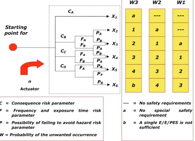
3.1.4 Risk graph... 64
3.1.5 Fault tree analysis ... 67
3.1.6 Event tree analysis ... 68
3.1.7 LOPA ... 69
3.1.8 Reliability Block Diagram analysis ... 70
3.1.9 Markov Modelling ... 75
3.1.10 HAZOP... 77
3.1.11 Comparison and evaluation of tools suggested by the standards ... 77
3.2 OVERVIEW OF IEC61882HAZOP STANDARD... 78
3.3 OVERVIEW OF PREPARING HAZOP STUDY... 81
3.3.1 About the hazards situations in general ... 81
3.3.2 General requirements of evaluating hazards and risks ... 83
3.3.3 What is Hazard and Risk analysis According to the Safety Standards? ... 83
3.3.4 General requirement of preparing Hazard and Risk analysis... 84
3.4 OVERVIEW AND CRITICAL ANALYSIS OF RECENT HAZOP PRACTICE... 85
3.4.1 Overview of HAZOP methodology ... 85
3.4.2 Overview of cost effective HAZOP studies ... 86
3.4.3 Automating of preparing HAZOP study ... 87
3.4.4 Functional approach of HAZOP ... 88
3.4.5 Comparison of traditional HAZOP and functional HAZOP... 88
3.4.6 Knowledge-based expert system ... 88
3.4.7 Problems of the recent solutions... 89
3.5 DEVELOPMENT OF NEW SOLUTION OF PREPARING HAZOP... 89
3.5.1 HAZOP manager: cost effective HAZOP study solution ... 90
3.5.2 HAZOP template example... 93
3.5.3 Summary and evaluation... 97
3.6 IMPLEMENTATION OF THE TEMPLATE HAZOP METHOD INTO TOOL4S SOFTWARE... 97
3.6.1 Objective of Tool4S SOFTWARE ... 97
3.6.2 Requirement of Tool4S SOFTWARE ... 97
3.6.3 Result of development of Tool4S software... 98
3.6.4 Description of Tool4S software ... 98
4 MANAGEMENT OF RISK ASSESSMENT: CUMULATIVE LOPA... 99
4.1 OVERVIEW OF LOPA METHOD... 99
4.1.1 History of LOPA method ... 99
4.1.2 Basic about LOPA ... 100
4.1.3 Objectives of LOPA procedure ... 101
4.1.4 Why is LOPA used for SIL determination? ... 102
4.1.5 SIL calculation with LOPA method... 103
4.1.6 LOPA method in the practice ... 105
4.2 CRITICAL EVALUATION OF THE SIMPLE LOPA METHOD... 106
4.2.1 Critical evaluation and comparison of LOPA methods ... 107
4.3 DEVELOPMENT NEW METHOD OF LOPA CALCULATION: CUMULATIVE LOPA ... 108
4.3.1 Cumulative LOPA calculation process... 108
4.3.2 Cumulative LOPA calculation algorithm ... 110
4.4 IMPLEMENTATION OF CUMULATIVE LOPA METHOD SOFTWARE:TOOL4S ... 113
4.5 SUMMARY AND CONCLUSION... 115
5 SIS DESIGN MANAGEMENT: PRACTICAL INTERPRETATION OF THE PROCESS SAFETY STANDARDS... 117
5.1 OVERVIEW OF SIS DESIGN... 117
5.1.1 Objectives of SIS Design ... 117
5.1.2 Requirement of SIS Design... 117
5.2 INTEGRATION AND SEPARATION OF BPCS AND SIS... 117
5.2.1 Why separation is requested? ... 118
5.2.2 Separation of information between SIS and BPCS ... 119
5.2.3 Separation of functions between SIS and BPCS... 119
5.3 COMMON CAUSE FAILURES... 120
5.3.1 Common cause within SIS ... 120
5.3.2 Common cause between SIS and BPCS ... 122
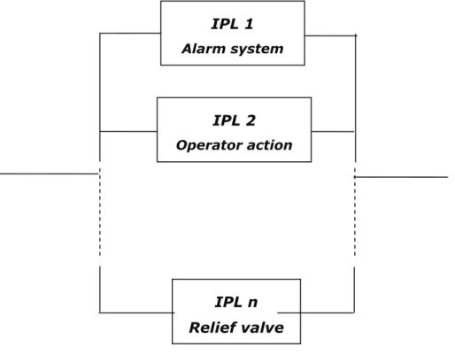
5.3.3 Common cause between IPLs... 122
5.4 SYSTEM BEHAVIOUR ON DETECTION OF FAULT... 123
5.4.1 Hardware Fault Tolerance and its realisation ... 124
5.4.2 Hardware fault tolerance ... 124
5.4.3 Minimum hardware fault tolerance of PE logic solvers ... 125
5.4.4 Minimum hardware fault tolerance of sensors and final elements... 126
5.4.5 Exception for hardware fault tolerance in case of sensors and final elements 127 5.4.6 Minimum hardware fault tolerance according to IEC 61508... 128
5.4.7 Prior in use... 128
5.4.8 Role of diagnostic... 129
5.4.9 Requirements for selection of components and subsystems ... 130
5.5 SISDESIGN VERIFICATION... 130
5.5.1 Pre-validation ... 130
5.6 SUMMARY AND CONCLUSION... 130
6 SIS MAINTENANCE MANAGEMENT: PROOF TEST MANAGEMENT ... 132
6.1 OVERVIEW OF PROOF TESTING ACCORDING STANDARD... 132
6.2 OVERVIEW AND CRITICAL ANALYSIS OF RECENT PRACTICE... 135
6.2.1 SIF and failure rates ... 135
6.2.2 Critical analysis of proof test model according to IEC 61511 ... 136
6.2.3 Critical analysis of recent practice... 138
6.2.4 Proof test scheduling ... 139
6.2.5 Proof test interval and proof test strategy ... 140
6.3 PROOF TEST COVERAGE FACTOR... 141
6.3.1 Imperfect proof testing ... 141
6.3.2 Coverage factor approach... 142
6.3.3 Problems with coverage factor approach... 143
6.4 NEW MODEL OF UNDETECTED DANGEROUS FAILURES... 144
6.4.1 Degraded failure model concept ... 145
6.4.2 Markov model of the new development... 146
6.5 SIMULATION RESULTS OF THE NEW MODEL... 147
6.6 SUMMARY AND CONCLUSION... 149
7 THESIS ... 150
1 INTRODUCTION AND AIM OF THE WORK... 150
2 NEW SCIENTIFIC RESULTS ... 151
3 RESULTS IN THE PRACTICE ... 153
4 FURTHER RESEARCH POSSIBILTIES ... 154
Table of Figures
FIGURE 1 RISK REDUCTION CONCEPT 24
FIGURE 2 SEVESO II RISK TABLE 28
FIGURE 3 DYNAMICS OF PROCESS BEHAVIOURS 32 FIGURE 4 HISTORY OF PROCESS SAFETY STANDARD 35 FIGURE 5 SURVEY ABOUT 34 CASE STUDY OF INDUSTRIAL DISEASE 34 FIGURE 6 IEC 61509 LIFE CYCLE STRUCTURE 38 FIGURE 7 IEC 61511 LIFE CYCLE STRUCTURE 39 FIGURE 8 APPLICATION DIFFERENCES BETWEEN IEC 61508 AND IEC 61511 42 FIGURE 9 COMPARISON OF BPCS AND SIS STRUCTURE 45
FIGURE 10 TREE STRUCTURE OF FAILURES 134
FIGURE 11 EXAMPLE OF FAULT TREE ANALYSIS 68
FIGURE 12 EVENT TREE ANALYSIS EXAMPLE 69
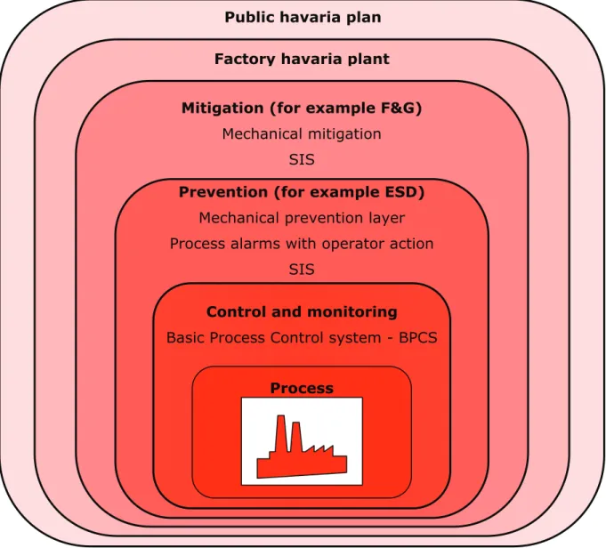
FIGURE 13 ONION-PEEL-MODEL OF LOPA 70
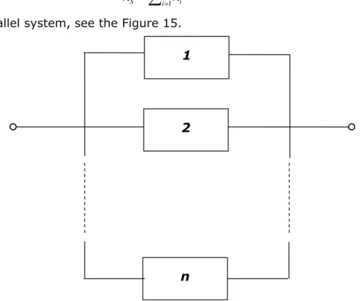
FIGURE 14 RELIABILITY BLOCK DIAGRAM, 2OO3, 1OO2 VOTING EXAMPLE 71 FIGURE 15 LINKAGE OF N COMPONENTS INTO A SERIAL STRUCTURE 71 FIGURE 16 LINKAGE OF N COMPONENTS INTO A PARALLEL STRUCTURE 72
FIGURE 17 IPL AS PARALLEL SYSTEM 74
FIGURE 18 MARKOV MODEL, SINGLE NONREPAIRABLE COMPONENT 76 FIGURE 19 MARKOV MODEL, SINGLE REPAIRABLE COMPONENT 76
FIGURE 20 MARKOV MODEL, 2*2 MATRIX 76
FIGURE 21 EXAMPLE OF A NATURAL GAS BURNER 94 FIGURE 22 EXAMPLE OF THE FUNCTIONALITY OF THE FURNACE TEMPLATE 94 FIGURE 23 EXAMPLE OF GAS BURNER’S HAZARD SCENARIOS 95 FIGURE 24 EXAMPLE OF MAIN GAS BURNER PRESSURE HIGH HAZARD SCENARIO 95 FIGURE 25 EXAMPLE OF MAIN GAS BURNER PRESSURE LOW HAZARD SCENARIO IN
EDITABLE MODE 96
FIGURE 26 EXAMPLE OF MAIN GAS BURNER PRESSURE LOW HAZARD SCENARIO, SIF
SRS 97
FIGURE 27 STRUCTURE OF A LOPA DIAGRAM 100
FIGURE 28 TYPICAL LOPA STRUCTURE 102
FIGURE 29 METHOD OF SIL CALCULATION 104
FIGURE 30 CUMULATIVE LOPA CALCULATION PROCEDURE 112 FIGURE 31 EDIT PFD VALUE OF SAFEGUARDS IN TOOL4S SOFTWARE 114 FIGURE 32 DEFINITION OF NON-MITIGATED FREQUENCY MATRIX OF CAUSES 114 FIGURE 33 DEFINITION OF TOLERABLE FREQUENCY MATRIX 114
FIGURE 34 EXAMPLE FOR RISK RANKING 115
FIGURE 35 EXAMPLE FOR THE RESULT OF A CUMULATIVE LOPA 115
FIGURE 36 SIS AND BPCS INDEPENDENCE 118
FIGURE 37 EXAMPLE OF POWER SUPPLY SEPARATION WITHIN SIS 121 FIGURE 38 EXAMPLE OF COMMON CAUSE OF IPLS 123 FIGURE 39 PROOF TEST MODEL INSPIRITED BY IEC 61511 137 FIGURE 41 PROOF TEST MODEL IN THE REALITY, BASED ON IEC 61511 137 FIGURE 42 PFD – TIME FUNCTION WITH 100% COVERAGE FACTOR ACCORDING TO IEC
61511 139
FIGURE 43 PFD TIME FUNCTION WITH NOT 100% COVERAGE FACTOR ACCORDING TO
IEC 61511 140
FIGURE 44 NEW MODEL OF PROOF TEST 138
FIGURE 45 CONCEPT OF PROOF TEST FROM IEC 61508N 141 FIGURE 46 PFD WITH PROOF TEST COVERAGE FACTOR 143
FIGURE 47 CLASSICAL DU FAILURE MODEL 145 FIGURE 48 NEW DU FAILURE MODEL (“DEGRADED FAILURE MODEL”) 146 FIGURE 49 MARKOV MODEL OF THE “DEGRADED FAILURE MODEL” 147
FIGURE 50 NO DEGRADATION FAILURE 148
FIGURE 51 SUDDEN FAILURE 148
FIGURE 52 DEGRADATION FAILURE 149
Tables
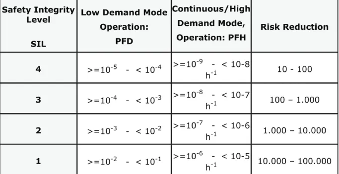
TABLE 1 HOW IEC 61508 BUILDS UP ... 37
TABLE 2 SIL DEFINITION AND RISK REDUCTION FACTOR ... 40
TABLE 3 PROGRAM FOR RESEARCH QUESTION 1 ... 55
TABLE 4 PROGRAM FOR RESEARCH QUESTION 2 ... 55
TABLE 5 PROGRAM FOR RESEARCH QUESTION 3 ... 56
TABLE 6 PROGRAM FOR RESEARCH QUESTION 4 ... 57
TABLE 7 RISK MATRIX EXAMPLE... 63
TABLE 8 DEFINITION OF CONSEQUENCE CATEGORY ... 64
TABLE 9 DEFINITION OF PROBABILITY CATEGORY ... 64
TABLE 10 TYPICAL RISK GRAPH METHOD ... 65
TABLE 11 DEFINITION OF RISK PARAMETERS: CONSEQUENCE ... 65
TABLE 12 DEFINITION OF RISK PARAMETER: FREQUENCY ... 66
TABLE 13 DEFINITION OF RISK PARAMETER: POSSIBILITY OF AVOIDING ... 66
TABLE 14 DEFINITION OF RISK PARAMETER: OCCURRENCE ... 66
TABLE 15 TRUTH TABLE FOR A I=3... 73
TABLE 16 2OO3 VOTING SYSTEM ... 74
TABLE 17 EVALUATION AND COMPARISON OF HAZARD AND RISK ANALYSIS METHODS ... 77
TABLE 18 TOLERABLE FREQUENCIES FOR PEOPLE’S HEALTH & SAFETY... 82
TABLE 19 TOLERABLE FREQUENCIES FOR ECONOMIC AND BUSINESS CONSEQUENCES82 TABLE 20 TOLERABLE FREQUENCIES FOR ENVIRONMENTAL CONSEQUENCES... 82
TABLE 21 HFT FOR LOGIC SOLVER ... 125
TABLE 22 HFT FOR SENSOR, FINAL ELEMENTS SUBSYSTEMS ... 126
TABLE 23 VOTING AND HFT... 127
TABLE 24 HARDWARE SAFETY INTEGRITY: ARCHITECTURAL CONSTRAINTS ON TYPE B SAFETY-RELATED SUBSYSTEMS ... 128
TABLE 25 EXAMPLE SIF (PRESSURE TRIP) ... 142
TABLE 26 INFLUENCE OF PTC ON PFDAVG FOR A GENERIC AIR ACTUATED BALL VALVE WITH 3-WAY SOV ... 143
Abbreviations ALARP As Low As Reasonable Possible
AIB Automated Independent Backup
ANSI American National Standards Institute
APC Advance Process Control
ARL Acceptable Risk Level
ATEX Atmosphere Explosive
BPCS Basic Process Control System (IEC 61511)
CAPEX Capital Expense
CC Common Cause
CCPS Centre of Chemical Process Safety (USA) CE matrix Cause and Effect Matrix
CFR Code of Federal Regulation (USA) C&E Cause and Effect
DCS Distributed Control System
DC Diagnostic Coverage
E/E/PE Electric/Electronic/Programmable Electronic
EMC Electro Magnetic Compatibility
EPA Environmental Protection Agency (USA) EPC Engineering and Procurement Contractor ERRF External Risk Reduction Facility
ESD Emergency Shut Down
ETA Event Tree Analysis EUC Equipment Under Control FAR Fatal Accident Rate
FAT Factory Acceptance Test
FEL Front End Loading
FMEA Failure Mode and Effect Analysis
FTA Fault Tree Analysis
FSQM Functional Safety Quality Manual HAZOP Hazard and Operability
H&RA Hazard and Risk Analysis
HSE Health Safety and Environment
IEC International Electrotechnical Commission IEV International Electrotechnical Vocabulary IPF Instrumented Protective Function
IPL Independent Protection Layer
ISA Instrument Society of America and Control
ISO International Organization for Standardization ISS Integrated Safety System
LOPA Layer of Protection Analysis LS Logic Solver (Safety PLC)
LTI Lost Time Injuries
MIR Maturity Index on Reliability
MIS Management Information System
MOC Management Of Change
MOS Maintenance Override Softwareitch MSDS Material Safety Data Sheets
MTBF Mean Time Between Failure MTTF Mean Time To Failure
MTTR Mean Time To Repair
OPEX Operation Expense
OSHA Occupational Safety and Health Administration (USA)
PDP Product Development Process
PHA Process Hazard Analysis
PLC Programmable Logic Controller
POS Process Override Switch PRP Product Realization Process PFD Probability of Failure on Demand
PFDavg Average Probability of Failure on Demand PFSavg Average Probability of a Safely tripped process
PHA Process Hazard Analysis
P&ID Piping and Instrumentation Diagram
PSM Process Safety Management
PT Proof Test
PTM Proof Test Management
RBD Reliability Block Diagram
QMS Quality Management System QTRM Qualitative Tolerable Risk Matrix
RMP Risk Management Plan
RR Risk Reduction
RRF Risk Reduction Factor
PST Partial Stroke Test
SAM Safety-Related Activity Management SAT Site Acceptance Test
SF Safety Function
SIF Safety Instrumented Function
SFF Safe Failure Fraction
SHE Safety, Health and Environment
SIF Safety-Instrumented Function
SIL Safety Integrity Level
SIS Safety-Instrumented System
SLAM Safety Lifecycle Activity Management SLC Safety Life Cycle
SLM Safety Lifecycle Management
SMS Safety Management System SR Safety-Related
SRS Safety-Related System
SRS Safety Requirement Specification
STR Spurious Trip Rate
SOFTWAREIFT Structured What If Technique TI Off-line Proof Test Interval
TR Trip Rate
TSRS Other Technology Safety Related System
1 Safety and Risk: introduction into the Process Safety
In this Chapter 1 it was overviewed the History of safety, development of the related Standards and Directives, without completeness focusing only those which important in our Thesis following the sub-clause of the standards referred.
The history of safety thinking is going back to the very beginning of the nineteenth century (1815) when Sir Humpry Davy developed the first firedamp (now According to ATEX it is explosion proof) lamp. The Davy lamp is a safety lamp containing a candle. It was created for use in coal mine, allowing deep seams to be mined despite the presence of methane and other flammable gases.
Davy had discovered that a flame enclosed inside a mesh of certain fineness cannot ignite firedamp. The screen acts as a flame arrestor; air (and any firedamp present) can pass through the mesh freely enough to support combustion, but the holes are too fine to allow a flame to propagate through them and ignite any firedamp outside the mesh. The first trial of a Davy lamp with a wire sieve was at Hebburn Colliery on 9 January 1816.
The lamp also provided a crude test for the presence of explosive gases. If flammable gas mixtures were present, the flame of the Davy lamp burned higher with a blue tinge. Miners could also place a safety lamp close to the ground to detect gases, such as carbon dioxide, that are denser than air and therefore could collect in depressions in the mine; if the mine air was oxygen-poor (asphyxiate gas), the lamp flame would be extinguished (black damp or chokedamp).
This application contains some important principles which become standards nowadays:
The first principle is the protection of the human life even the business losses (the mine is destroyed).
The second principle, how to handle the explosive gases was leading to ATEX directives and standards [ATX_100], [ATX_137]. Now it is part of the „good engineering practice” in the area where explosive gases are present in the technology
The third principle is the detection of explosive, even toxic (oxygen-poor air) gas mixtures nowadays are known as Fire&Gas application
The forth principle is prevention and mitigation philosophy as a basic principle in the safety
1.1 Why Process Safety is so important?
A Brussels Report stated in 2002:
“According to European Statistics, in EU-15, because of an accident at work one worker becomes a victim every 5 seconds and one worker dies every two hours. In 2001, this means 7.6 million accidents at work, 4.9 million of these resulted in more than 3 days of absence from work and 4 900 fatalities. The cost of accidents at work and occupational diseases in EU 15 ranges for most countries from 2.6 to 3.8% of Gross National Product (GNP).
Additionally, in 2002 in new EU member states were almost 2.5 million accidents at work and 1 400 fatalities were recorded. Besides the accidents at work, major accidents results extensive consequences to people, environment and the property. A major accident such as the Toulouse disaster on 21st September 2001 resulted in 1 500 million € of damages, 27 000 homes and 1 300 companies damaged. The explosion killed 30 people (21 on site with 10 employees and 11 sub-contractors, 9 off-site), 2 242 were injured (officially), and 5 000 persons have been treated for acute stress. This disaster has upset the public, traumatised an industrial city and led the politicians to close down the AZF plant (450 direct jobs) and the SNPE phosgene related activities (492 jobs, 600 sub-contracting jobs).”
Over the facts and statistics, many good reasons can be enumerated that justify the application of the various safeguarding measures in the process industry.
These reasons can be divided as follows:
Protect people from harm.
Protect the environment.
Satisfy laws and regulations.
Reduce production losses and down time and cost due to damage of equipment.
Lower losses due to negative impact on ‘company image’.
Lower plant risk profile (Insurance premium cost).
Whether these aspects are relevant or not, depends on the typical application, environmental circumstances, and requirements from local legislation. It is the responsibility of a company (According to the Standards called “Operator”) to establish the need of dealing with these aspects.
1.2 Growing complexity of industrial processes
In the last decades, industrial processes are becoming more and more complex [Lee_96]. Expanding product and production requirements led to further optimization of the concerned processes. The continuously increasing competition, and application of Advance Process Control (APC) solutions to increase productivity of Plants, is forcing process installations to operate closer and closer to their limits.
High level instrumentation, which also makes process control more and more complex, is expected to control the technology and safeguard these processes.
As a consequence of the growing complexity of the process installations, the control instrumentation, and safeguarding instrumentation, safety-related business processes have become even more difficult to manage [Kne_00], [Kne_98]. Furthermore, many individuals and organizations are involved in the design, implementation, and operation of process installations, including the end- user, the engineering contractor, the system integrator, and the equipment suppliers. For instance, let me consider an oil company that decides to build a new refinery at a certain location. Normally, an engineering contractor, who becomes responsible for the design and realization of the new installations, is hired. Dedicated system integration engineering companies are assigned to provide automated process control equipment.
Manufacturers, vendors, and suppliers of instruments all are responsible for the design and development of those instruments but they are also interested in
making profit which is sometimes in conflict with the technical content of the supplied solution.
The only way of overcome this type of problems to prepare a HAZOP study and SIL calculations at the earliest stage of the project, when all documentation is accessible for preparing the studies. Preparing the HAZOP study is the best method of avoiding both over engineering and under engineering.
Using LOPA [AIC_01], [AIC_2] method for the SIL calculation one have possibility of reducing the cost of the complete “Integrated Safety System”, see Chapter 2.5.
1.3 History of the Directives and Safety Standards
The general safety consideration is simultaneous with the Technology itself. The first technologies were the mining, later on machines for the mining. The first breakthrough was the developing of the steam machines, where the over pressure protection was the first recognition of the hazards in the steam technology after analysing the consequences of the overpressure for the people (may be killed) and business losses (machine broke down).
This period of time was an accident driven safety device (even standards) development age, where “first accident, then action” was the basic. The more accident happened, the more effort was of developing protective devices, methods and regulation and the result was forming and accepting the “good engineering practice” philosophy. This philosophy is more or less valid in recent days also, but the globalisation will not help to provide higher safety in the work, without having world wide Process Safety Standards, and being different Safety culture in the different countries of world wide.
The safety questions could be divided in three segments which were not developed parallel:
Mechanical engineering like overpressure protection, chemical resistance, corrosion etc.
Safety problems connected to Electrical engineering like electrocution, over voltage protection, lighting protection, surge protection and EMC.
Process engineering like explosive and toxic technologies, batch technologies.
In this progress the first step was done by the mechanical engineers developing safer and safety machines and equipment using more safe materials and developing mechanical safety devices as well laying down the basis for the standardisation in the field of mechanical engineering like pressurised vessel and equipments, material standards etc.
In the field of electrical engineering this progress started later, when the electricity becomes the part of our everyday life. The first step was the protection of human life against the electrical shock (electrocution) and first started a standardisation process in the application of electricity in the non-explosive surrounding, and later on in explosive technologies. Nowadays the result is positive as the ATEX 100 [ATX_100], ATEX 137 [ATX_137] and EN 1127 1 – 7 [EN_1127] become a good engineering practice for the electrical engineers and
end users also. These standards are based on laboratory research involving a lot of measurement, proving that anybody following these standards will be protected against explosive problems using electric, electronic equipments in explosive atmosphere. The approach of these standards is deterministic.
In the field of Process Industry there was no similar improvement of the area of safety like in the area of Mechanical and Electrical engineering. It happened in the seventies of last century some very serious accident in Europe and world wide like Dow Chemical plant in Bhopal, India or Seveso, Italy which focused the attention on the negative consequence for the human life and environment in case of accident. The result of the first action in Europe was the SEVESO I Directive I directive in 1987 and SEVESO II Directives was accepted by 12 European countries in late seventies of last Century [SEV_II]. The main goal of this Directive was the protection of the public in case of similar accident which would happen in plant having explosive and toxic material in a technology, storing, processing and transporting them.
In the US, the Government control the process industry if the industry itself unable to control its activity. The first result of this action was issuing the ISA- TR84 process safety Standard which was followed by the Application Guides in 2001 – 2003 [ISA_TR84].
Meanwhile in Europe, based on the German Standards, the IEC 61508 1 – 7 [IEC_508] standards were published in 1998. This generic (industrial segment independent) standard was followed by the IEC 61511 1-3 [IEC_511] Process Industry Safety standards in 2003. This latest standard is valid in the Chemical, Petrochemical, Oil and Gas and Pharmaceutical Industry. These two standards were accepted in Europe and, joining to European Community, in Hungary also.
In Europe the Directives are mandatory while the Standards are only recommended, but there are three exceptions:
Any Government can make it mandatory (Sweden, Norwegian)
May be involved in the contract between two parties
It would be dedicated as “Good Engineering Practice” like in USA.
In USA the IEC 61511 was introduced as ANSI/ISA 84.00.01 2004 Part 1 – Part 3 (IEC 615111 Part 1 – Mod) [ISA_84] and was dedicated as “Good Engineering Practice”. In USA there was an attachment called “Grandfather Law”.
In the field of Factory Automation one shall take into consideration the IEC 61508 and IEC 62061 [IEC_61] (machine specific standard) also.
1.4 Functional Safety
Functional Safety is the most often used expression in my thesis that is why it is so important to define what means in practice [BÖR_08].
With the introduction of electronic programmable system in the safety relevant applications, “Functional Safety” has become a central concept. The term
“Functional safety” appears in the titles of the international standards IEC 61508 [IEC_508] and IEC 61511 [IEC_511], published a number of years ago.
In general, “Functional Safety” means that a component or a system performs its safety-relevant task correctly and in accordance with the risk to be managed.
The system either performs this function, or if internal faults or failure occur, or it will assume a pre-defined safe state.
To fulfil this requirement, an understanding of safety engineering and a comprehensive knowledge of the existing standards are required. This begins with examining a safety systems life cycle, performing hazard and risk analysis (HAZOP study: Chapter 3), specifying the safety-related components and systems (LOPA study: Chapter 4), developing and implementing the system (SIS design: Chapter 5), and the process ends with system’s operation and maintenance (SIS maintenance, Proof test Chapter 6).
1.5 Correlation between Risk, Acceptable Risk, Residual Risk and Risk Reduction
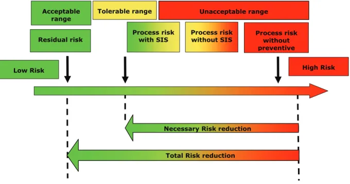
The Figure 1 shows how the risk would be decreased to acceptable level. That is the basic principle of risk reduction for a given hazard independently the type of the risk involved. This figure shows in plausible manner the influence of specific safety measures on risk reduction.
The existing risk must be reduced at least to acceptable risk, which is not always purely objective rather strongly dependent and influenced by subjective opinions.
The Figure 1 makes it obvious that the risk is reduced not only through SIS (Safety Instrumented System) safety measures, but also through different measures like release valve and other not instrumented system involving engineering, trainings etc. This non SIS safety measures influence the risk parameters and consequently lead to decrease of SIL value of SIFs. The safety of a system could be reached therefore in different but equivalent ways. The conducted measures can be mutually supplement or replace each others.
The requirement arise from a given safety goal and partial risk that should be covered by the SIS safety equipments. This partial risk is being described quantitatively through these parameters (see more about SIL calculation in Chapter 4.1.4). With their help the SIL values can be calculated. An exact gradual allocation of measures to the different requirements however is not possible, mainly because of the possible measures are very diverse.
Figure 1 Risk reduction concept 1.6 SEVESO Directives
1.6.1 Introduction
Consequence of increasing industrialization is the significant increase of accidents involving dangerous substances (toxic and explosive as well). There was some initiative accident in Europe.
The so called Seveso Directive [SEV_II] is concerned with the prevention concept and the overall assessment of certain industrial activities with view of plant safety and environmental protection as a first harmonisation step on European level in 1982.
Following this Directive, Member States shall introduce the necessary measures to ensure that the competent authorities will get all information regarding to the plant, the substances and operational conditions involved. The Seveso Directive applies to both new and already existing industrial activities. It has been amended several times (last amended by Directive 96/82/EC).
1.6.2 Seveso disaster
‘Seveso” accident happened in 1976, a Sunday afternoon in Seveso, Italy, where dioxin and other dangerous substances were diffused through a broken valve in total amount of 200 ton and amount of 1 ton of Dioxin into the air, to be the following consequences:
disease similar to sunburn within 5 days
80.000 domestic animal were killed
More than 600 people had to be evacuated
2.000 people were treated for dioxin poisoning
Residual risk Process risk
without preventive Unacceptable range
Tolerable range Acceptable
range
Low Risk High Risk
Process risk without SIS Process risk
with SIS
Necessary Risk reduction
Total Risk reduction
20 acre forest were planted in the place of the plant 1.6.3 Seveso directives history
1982: 82/501/EEC Seveso Directive was adopted and accepted by all member of EU.
1984, Bhopal, India, Union Carbide: leak of methyl isocyanides caused more than 2.500 death.
1986, Basel, Switzerland, Sandoz: water contaminated with mercury, organophosphate pesticides caused death of half a million fish in the Rhine.
1987: SEVESO directive was amended by directive 87/216/EEC and in 1988 SEVESO directive was amended by directive 88/610/EEC.
1996: 96/82/EC Seveso II Directive was adopted and the SEVESO II Directive has fully replaced its predecessor. Member states had up to 2 years to bring into force the national laws, regulations and administrative provision to comply with the Directive. From 3 February 1999 the adherence of the Directive have become mandatory for the Member States
Important changes:
Extension of the scope
Introduction of new requirements related to safety management systems (application According to IEC 61508 [IEC_508] and IEC 61511 [IEC_511]
for the process industry
Emergency planning
Land-use planning
Reinforcement of the provisions on inspections
Introduction of new requirements relating to safety management systems
Emergency planning
Land-use planning
Reinforcement of the provisions on inspections 1.6.4 Objectives of Seveso directives
The aim is two-fold:
Prevention of major-accident hazards involving dangerous substances and limitation of the consequences of the accidents that occur:
For human being safety and health aspect
From environmental aspect
Both aims can ensure high levels of protection throughout the Community in a consistent and effective manner.
Scope of SEVESO II [SEV_II] directive is presence of dangerous substances in establishments and it covers:
Industrial activities
Storage of dangerous chemicals and
Transporting dangerous materials
1.6.5 Requirements of Seveso Directive
Company who holds less dangerous substance than the threshold levels given in the Directive is not covered by this legislation, but will be controlled by general provisions on:
Health
Environment
Business
Lower tie: Companies who hold a larger quantity of dangerous substance, above the lower threshold will be covered by the lower tier requirements
Upper tie establishments: Companies who hold even larger quantity of dangerous substance, above the lower threshold will be covered by all the requirements of the Directive.
The Directive contains general and specific obligations on both Operators (Company Owners) and Member States’ authorities. Provisions fall into two main categories:
Prevention of major accidents.
If it may happen then limitation of consequences of major accidents (mitigation).
Operators, coming under the scope of the Directive, needs to send a notification to the competent authority, to establish a Major-Accident Prevention Policy and also in case of upper tier establishments they need to establish:
Safety Report
Safety Management System According to IEC 61508 [IEC_508] and IEC 61511 [IEC_511].
Emergency Plan.
We have to consider the development of new managerial and organizational methods when introducing the Functional Safety Management System, as over the past 10 years significant changes have occurred in industrial practice relating to risk management (see IEC 61508 [IEC_508] and IEC 61511 [IEC_511] in the Process Industry). According to statistics since 1982 the management factors is proven to be a significant causative factor in over 90 % of the accidents in the EU. The main objectives are: to prevent or reduce accidents caused by management factors.
1.6.6 Improvement of SEVESO Directives
There were happened three industrial accidents generating the extension of SEVESO II Directive by the Directive 2003/105/EC on 16/12/2003 with deadline of 1 July 2005 [SEV_II]. These accidents were:
Enschede Firework exploded,
Toulouse, France ,fertilizer explosion, 2001, Ammonium nitrate explosion,
Baia Mare (Nagybánya), Romania, spread of cyanide spill, 2002 Made the Tisza river dead for a period of time
Most important aim of the extensions to cover risk arising from:
Storage and processing activities in mining (Baia Mare, Nagybánya, cyanide contamination, Tisza and Danube)
Pyrotechnic and explosive substances (Enschede, explosion in a firework manufacturing plant)
Ammonium nitrate and ammonium nitrate-based fertilizers (Toulouse, fertilizer explosion).
The last version of SEVESO Directive is DIRECTIVE 2003/105/EC OF THE EUROPEAN PARLIAMENT AND OF THE COUNCIL of 16 December 2003 [SEV_II]
and the Hungarian version is the “18/2006. (I. 26.) Korm. rendelet a veszélyes anyagokkal kapcsolatos súlyos balesetek elleni védekezésről” [SEV_HUSEV_II].
The SEVESO II Directives are basic Process Safety Standards with aim of protection of public from the Industrial diseases. An important statement of the SEVESO II Directives:
“(15) Whereas analysis of the major accidents reported in the Community indicates that the majority of them are the result of managerial and/or organisational shortcomings; whereas it is therefore necessary to lay down at Community level basic principles for management systems, which must be suitable for preventing and controlling major-accident hazards and limiting the consequences thereof;”
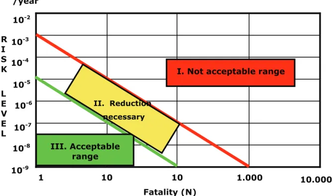
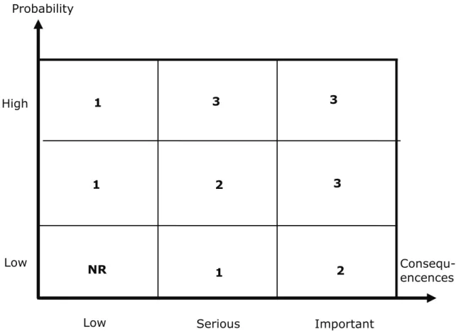
This statement of the SEVESO II Directive leads to the application of IEC 61508 [IEC_508] general and IEC 61511 [IEC_511] Process Safety Standards in which specific obligations of the operator shall be in consideration the build up and maintain the Functional safety for all the life cycle of the Plant referred, including the safety/protection systems. The cornerstone figure of Company QTRM for human is seen on Figure 2 (10-5 fatality rate).
Figure 2 SEVESO II Risk table 1.7 ATEX Directives
ATEX abbreviation means Atmosphere Explosive and ATEX Directives are dealing with and covering installations of electric, electronic equipments in explosive atmosphere. ATEX Directives (ATEX 100 [ATX_100], ATEX 137 [ATX_137]) are mandatory in Europe.
1.7.1 Introduction
Explosive atmospheres can be caused by flammable gases, mists or vapours or by combustible dusts. If there is enough of the substance, mixed with air, then all it needs is a source of ignition to cause a gas or dust explosion.
Explosions can cause loss of life and serious injuries as well as significant damage. There are two widely used ways of reducing the risk:
Preventing releases of dangerous substances, which can create explosive atmospheres.
Preventing sources of ignition being present. Using the correct equipment can help greatly in this.
An explosive atmosphere is defined as a mixture of dangerous substances with air, under atmospheric conditions, in the form of gases, vapors, mist or dust in which, after ignition has occurred, combustion spreads to the entire unburned mixture.
Many workplaces may contain, or have activities that produce, explosive or potentially explosive atmospheres. Examples include places where work activities
FB
1 10 10 1.000 10.000
10-9 10-8
10-7 10-6 10-5 10-4 10-3 10-2
Fatality (N) R
I S K L E V E L
I. Not acceptable range
III. Acceptable range
II. Reduction necessary /year
create or release flammable gases or vapors, such as vehicle paint spraying, or in workplaces handling fine organic dusts such as grain flour or wood.
The ATEX Directives are dealing with equipments operated by electricity and installed and commissioned in explosive area.
1.7.2 ATEX Directives
ATEX is the name commonly given to the framework for controlling explosive atmospheres and the standards of equipment and protective systems used in this area. It is based on the requirements of two European Directives.
“1) Directive 99/92/EC (also known as ‘ATEX 137’ or the 'ATEX Workplace Directive’) on minimum requirements for improving the health and safety protection of workers potentially at risk from explosive atmospheres.”
The text of this Directive and the supporting EU guidelines are available on the EU-website.
“2) Directive 94/9/EC (also known as ‘ATEX 95’ or ‘the ATEX Equipment Directive’) on the approximation of the laws of Members States concerning equipment and protective systems intended for use in potentially explosive atmospheres.”
The text of this Directive and EU supporting guidelines are available on the EU website.
1.7.3 ATEX 100
Regarding to the explosion risk such a specific Directive 94/9/EC [ATX_100] has been adopted by the European Parliament and the Council concerning equipment and protective systems intended for use in potentially explosive atmospheres.
This Directive is well known as 'ATEX 100 a - Directive' [ATX_100]. The ATEX 100 a - Directive applies to all equipment capable of causing an explosion through their own potential sources of ignition. 'Equipment' means machines, apparatus, fixed or mobile devices, control components and instrumentation thereof and detection or prevention systems, separately or jointly.
ATEX 100a covers not only equipment itself but also “systems”. This point of view it applies even to safety devices, controlling devices and regulating devices intended for use outside potentially explosive atmospheres but required for or contributing to the safe functioning of equipment and protective systems with respect to the risks of explosion.
1.7.4 ATEX 137
Gases, vapours, mists and dusts can all form explosive atmospheres with air.
Hazardous area classification is used to identify places where, because of the potential for an explosive atmosphere, special precautions over sources of ignition are needed to prevent fires and explosions [ATX_137].
Hazardous area classification should be carried out as an integral part of the risk assessment to identify places (or areas) where controls over ignition sources are needed (hazardous places) and also those places where they are not (non hazardous places) present. Hazardous places are further classified in Zones which distinguish between places that have a high chance of an explosive atmosphere occurring and those places where an explosive atmosphere may only occur occasionally or in abnormal circumstances. The definitions of the Zones also recognise that the chance of a fire or explosion depends on the likelihood of
an explosive atmosphere occurring at the same time as an ignition source becomes active.
Assessing the risk means identifying hazardous or non-hazardous areas should be carried out in a systematic way. Risk assessment should be used to determine if hazardous areas exist and to then assign zones to those areas. The assessment should consider such matters as:
the hazardous properties of the dangerous substances involved;
the amount of dangerous substances involved;
the work processes, and their interactions, including any cleaning, repair or maintenance activities that will be carried out;
the temperatures and pressures at which the dangerous substances will be handled;
the containment system and controls provided to prevent liquids, gases, vapours or dusts escaping into the general atmosphere of the workplace;
any explosive atmosphere formed within an enclosed plant or storage vessel; and,
any measures provided to ensure that any explosive atmosphere does not persist for an extended time, e.g. ventilation.
Taken together these factors are the starting point for hazardous area classification, and should allow for the identification of any zoned areas. The following paragraphs give further information on what to consider during an assessment.
The properties of a dangerous substance, that need to be known, includes the boiling point and flash point of any flammable liquid, and whether the flammable gas or vapour that may be evolved is lighter or heavier than air.
For dusts, information on particle size and density will be needed, once it has been shown that a particular dust can form an explosive atmosphere. Often, relevant information is contained on a safety data sheet provided with the product.
Some potential sources of release may be so small that there is no need to specify a hazardous area. This will be the case if the consequence of an ignition following a release is unlikely to cause danger to people in the vicinity.
However, in the wrong circumstances ignition of quite small quantities of flammable gas/vapour mixed with air can cause danger to anyone in the immediate vicinity. Where this is the case, as in a relatively confined location, from which rapid escape would be difficult, area classification may be needed even where quite small quantities of dangerous substance are present.
The size of any potential explosive atmosphere is, in part, related to the amount of dangerous substances present. Industry specific codes have been published by a variety of organizations to provide guidance on the quantities of various dangerous substances that could be stored.
Hazardous places are classified in terms of zones on the basis of the frequency and duration of the occurrence of an explosive atmosphere. That means a probabilistic approach instead of deterministic approach involving a new direction in how the new standards are build up.
1.7.5 ATEX and Functional Safety
The statement of ATEX Directives are based on research and test in laboratories using acceptable safety margins and that is why ATEX directives now are part of the “Good Engineering Practice” in EU and proving a given level of Functional Safety. ATEX Directives are belonging to the very first step of the hazard and Risk analysis reflecting the questions like: is this technology explosive or not. In case of “YES” answer the designer shall follow the instruction the ATEX Directives and will design an “explosively safe” system control technique in electric point of view. Other words the electric, electronic equipment, installed in explosive atmosphere, will not be ignition source in case of loss of explosive containment (taking into consideration all possible release sources).
Application of ATEX Directives means an independent protection layer (IPL) for the explosive plants and as a minimum Functional Safety requirement shall be taken into consideration, but not given any credit to this protection layer as being part of the basic process control system.
When an “ATEX” component, like isolator for a transmitter which is installed in explosive atmosphere, is part of a safety instrumented loop (SIF), in the SIL calculation [EXI_1] one shall take into consideration the dangerous undetected failure rate of the isolators [IEC_508], [IEC_511], [BÖR_06] , [BÖR_08] being part of the Safety Instrumented Function loop (SIF). That means the use of SIL certified isolator is highly recommended.
Not following these Directives means a “built in Hazard” in the process and avoiding this is mandatory. In other words an explosive plant has to be
“explosively safe” before start-up, following the good engineering practice (ATEX Directives).
1.8 Process safety standards
In this chapter we overview the process safety standards: the history, objectives and requirements.
1.8.1 Process Safety in General
The chemical, oil and petrochemical, pharmaceutical and even in the food industry in both the dominant part of the raw materials and the products are explosive and/or toxic materials.
Figure 3 shows schematics how the process works. In this figure we summarised the typical process behaviour and this figure will show us the tasks of how to make our process safer and what the risk means: deviation from the design parameters.
From this figure one can see that what one should do to make his/her process safer. Every process, not having any protection layer, is inherently unsafe caused by any of the followings actions:
Lack of Hazard and Risk analysis
Poor design
Poor installation and commissioning
Poor maintenance and operation
Components failures
Device failures
Human/operators failures
Etc.
Figure 3 Dynamics of process behaviours
It is shown in Figure 3 that the process going out of the control (for example because of failures of BPCS) may reach the dangerous condition leading to explosion.
That is why one has to control this process during the overall life time of plant using protection layers like:
Engineering
Basic Process Control System.
Alarm system.
Emergency Shut Down system (Safety Instrumented System).
Active protection layers like relief valves.
Passive protection layers like dike.
Etc.
Trip Setting
Pre-alarm Setting
Process Safety Time
Time Process Variable Consequence Realised
Trip point
Pre alarm trip point
Process Safety Time Consequences realized
Any of this layers in general are functionally safe if the given layer performs its safety relevant task correctly (for example a relief valve open at preset 64 bar) and in accordance to the risk to be managed (ie. process is risky (exploded) above 64 bar). If the protection layer works correctly (functional safety) it drives the process into safe stage, in our case depressurises the process and leads the overpressure to the flare.
To fulfil this requirement, an understanding of safety engineering and a comprehensive knowledge of the existing standards are required.
1.8.2 Introduction
The history of the process safety standards started in the seventies of last century, when the first need of application of electronic equipment in safety system (ESD = Emergency Shut Down System) inducted [TÜV_73], [DIN_00], [DIN_81], [DIN_BAS], [DIN_54], [VDE_16]. This demand speeded up the process of application oriented standards developments. Overview about the development of the safety standards is shown in Figure 5.
The basic entity of Process Safety Standards is the Safety Related System (SIS – Safety Instrumented System) [IEC_511], [ISA_2004], which is used already for years for carrying out safety-related functions in the process industry. The safety system should drive the supervised process into safe state in case of demand.
The required safety function, protecting equipment, depend on many application specific factors and form a part of overall safety, which protect the equipment under control (BPCS). Safety, which is to be ensured by safety function, can be achieved by a multiplicity of protective systems, which are based on the most different technologies, like mechanics, pneumatics or programmable electronics.
These safety functions serve functional safety and reduce the risk of a functional loss with possible serious consequences. The question which safety function is used and where, is determined by a Process Hazards Analysis (PHA).
The term “safety system” is also replaced in different standards by the designation of “safety critical” or “safety-related system”. The general understanding of a “safety, safety critical or safety-related system” is a system, consisting of one or more safety function and which, if they fail, can lead to dangerous consequences. Therefore, it is necessary to develop safety critical system with certain minimum standard level, so that the demand on functional safety are fulfilled and can be reviewed.
In the standards numerous methods are described to perform safety analysis and are guaranteed that the safety systems fulfil the requirements of appropriate standards during of the overall life cycle.
The Figure 5 is shows the development of the Process Safety Standards from the first demand of application of microprocessor in safety system to nowadays.
The development of the Process Safety Standards focuses on (without completeness):
Operability of plants;
Maintainability of the plant;
Electric, Electronic and programmable Electronic equipment (referred in the standards as E/E/PES);
New approach of safety (life cycle philosophy, functional safety, integrated safety);
Statistical approach (Hazard and Risk analysis, ALARP, LOPA, probability, availability);
Component design (both HW and SOFTWARE);
System design (SIF, SIS, SIL);
Activities connecting to safety (design, installation, commissioning, validation, maintenance, management of change).
1.8.3 Life Cycle philosophy
In the late eighties of last century a survey was published about 34 serious industrial diseases and the result is shown in Figure 4.
Both IEC 61508 [IEC_508] and IEC 61511 [IEC_511] are based on the life cycle philosophy.
Figure 4 Survey about 34 case study of Industrial disease 44,1 % Specification
14,7 %
Design and Realization 5,9 %
Installation and Commissioning 14,7 %
Operation and Maintenance 20,6 %
Modification after installation (MOC)
Safety Instrumented System Management Page 35/160
StandardName, Content, Validation Application Specific IEC 61511, Process Industry IEC 61513, Nuclear Industr IEC 62061, Machinery Industry Programmable Logic Controller IEC 61131-2: Hardware Properties IEC 61131-3: Software Properties Basic Safety Standard IEC 61508, SIL 1…4 Safety Lifecycle Quantitative Considerations IEC 61508 Independent from Application
DIN 3100 – General Requirement, AK 1…8 DIN V VDE 081 Microprocessors in Safety Application DIN V 19250 Basic Safety Evaluation for Measurement & Control DIN V 19250 Requirements & Measures, Qualitative Consideration
withdrawn Application Oriented (example)
VDE 0116 Electrical Equipment for Burner Application DIN EN 954 Safety for Machinery
PrEN 50156 IEC 62016 PrEN ISO 13849 Available book TÜV Book, Microcomputer in Safety Application, Safety Classis 1…5 level Year 1982 1989 1990 2002 2004 Figure 5 History of process safety standard
This survey investigated and evaluated the root cause of the industrial accidents and the conclusion from this survey was to split this causes into five categories:
Specification phase
Design and realisation phase
Installation and commissioning phase
Operation and maintenance phase
Modification after installation This statistic spotlights the followings:
Important to maintain the functional safety through the whole life time of the system;
The cause of two third of the accidents was built in the system before start up.
This statistic also emphases the importance of the preliminary works, like hazard and risk analysis specifying the Safety Instrumented System (SRS), the completeness of the work procedures regarding activities involved in how the system is build up (SIS design, SIS installation and commissioning).
1.8.4 Management of Functional Safety
Conclusion of the survey (Figure 4) together with SEVESO Directive’s [SEV_II]
statement about the mandatory operation of Safety Management System within the given Company, and the detailed instruction about how the Functional Safety Management to be operated According to the Process Safety Standards, was to give the possibility of building up an integrated functional safety system covering all aspect of the safety (human, environment and business) within the given Company.
The Management of Functional Safety is a more complex issue of course, but our point of view less important, supposing that all Company has their own system.
Our thesis would give possibility for any Company to build in Application Guides, as part of Management of Functional Safety.
1.8.5 IEC 61508 Standard
The IEC 61508 [IEC_508] standard is a general one, sometime called umbrella or basic safety standard, covering all industrial segments, except nuclear industry, and it was published in 1998. The IEC 61508 standard consists of 7 volumes, see Hiba! A hivatkozási forrás nem található..
Figure 6 shows the basic philosophy of the IEC 61508, differing 16 different life cycle phase of a Safety Instrumented system.
The IEC 61508 (and IEC 61511 also) considers the safety-relevant function, i.e., it always covers an entire function chain, i.e., from sensors – to logic solver – to actuator. The represented function chain must completely fulfil the requirements of the respective safety integrity level matching the definition of IEC 61508. Thus the field bus systems are to be included into the picture.
The definition of the safety integrity level, described in Chapter 1.8.7, determines the range and effectiveness of the safety-relevant measures which must be realized in the Safety Instrumented Systems.
Table 1 How IEC 61508 builds up
IEC 61508-1 General Requirements 1998
IEC 61508-2 E/E/PES HW Requirements 2000
IEC 61508-3 E/E/PES Software Requirements 1998
IEC 61508-4 Definitions 1998
IEC 61508-5 Examples of methods for determination of SIL 1998 IEC 61508-6 Guidelines on the application of Parts 2 and 3 2000 IEC 61508-7 Overview of techniques and measures 2000
1.8.6 IEC 61511 Standard
The IEC 61511 [IEC_511] standard is a Process Industry specific safety standard, published in 2004. This standard is accepted in the US (ANSI/ISA—84.00.01—
2004 Part 1 - 3 (IEC 61511-1 - 3 Mod)) [ISA_84] and dedicated to “good engineering practice”.
The title of this standard is: “Functional safety: Safety Instrumented System for process industry sector”.
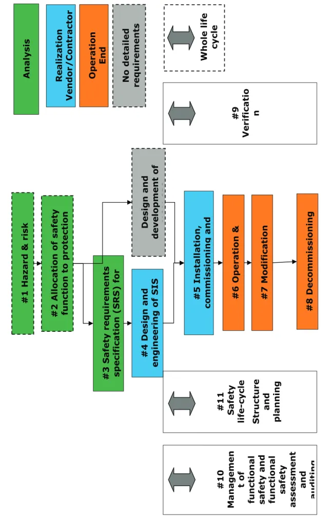
Figure 7 shows the basic philosophy of the IEC 61511, defining 8 different life cycle phase and three general ones covering the complete 8 phase. This international standard applies to safety-related system in the process industry.
Applying IEC 61511 to the process industry requires the execution of the hazard and risk analysis described in the first phase of this standard. From this analysis a specification for safety-relevant system can be provided. This standard fits within the framework of IEC 61508 applicable to the process industry. The terms, defined in the IEC 61508 “safety life cycle” and “safety integrity level” (SIL) forms the basis for the application of the international standard.
The safety-related system consists of those components and subsystems, starting from sensors through Logic Solver up to actuators, which are necessary for the execution of the specified safety-related functions. That is the end – to - end approach, taking into consideration the process side of the sensors and the process side of the actuator via safety logic solver.