Proceedings of the ASME 2020 International Design Engineering Technical Conferences &
Computers and Information in Engineering Conference IDETC/CIE 2020 August 16-19, 2020, St. Louis, USA
IDETC2020-22461
DRAFT: NUMERICAL AND EXPERIMENTAL BIFURCATION ANALYSIS OF TRAILERS
Hanna Zs. Horvath∗ Department of Applied Mechanics
Budapest University of Technology and Economics Budapest, 1111
Hungary
Email: hanna.horvath@mm.bme.hu
Denes Takacs
MTA-BME Research Group on Dynamics of Machines and Vehicles
Budapest, 1111 Hungary takacs@mm.bme.hu
ABSTRACT
A 4-DoF spatial mechanical model of trailers is used to an- alyze the snaking, rocking and roll-over motions. The deriva- tion of the governing equations is presented. The non-smooth characteristics of the tire forces are taken into account together with other geometrical non-linearities. Beyond the linear stabil- ity analysis the nonlinear vibrations are investigated via numer- ical continuation and simulations. Linear stability charts and bifurcation diagrams are constructed to identify the parameter ranges, where large amplitude vibration can occur. The domains of the snaking and the rocking motion are detected. Numerical simulations verify the existence of periodic solutions predicted by numerical bifurcation analysis. A small scale experimental rig is presented and the nonlinear vibration of the trailer is in- vestigated.
INTRODUCTION
The lateral stability analysis of vehicles is a crucial task in vehicle dynamics since the first car appeared on the roads. Al- though, the lateral dynamics and the related vibrations are an- alyzed many decades ago, they are still problems for engineers.
For example, the shimmy motion of steered wheels ( [1,2]), wob- ble motion of motorbikes ( [3]) and snaking/rocking motion of trailers ( [4–7]) are in focus nowadays.
∗Address all correspondence to this author.
In this paper, we deal with the mechanical modeling of trail- ers because several accidents are related to the lateral stability problem of them. The snaking motion of trailers or semi-trailers can emerge in certain velocity ranges in case of bad load condi- tions. Sometimes, the amplitude of the snaking motion increases and the trailer starts to jump from one of its wheels to the other, namely, the so-called rocking motion appears. This latter vibra- tion often leads to the roll-over of the vehicle causing a serious accident.
In order to construct an appropriate mechanical model, by which the formerly mentioned motions of trailers can be effi- ciently analyzed, the non-linear effects of the tire/road contact have to be considered. Beyond the strongly nonlinear lateral tire force characteristics, the disengagements of tires have to be in- cluded in the model too. As a consequence piece-wise smooth nonlinear differential equations describe the system that limits the application of analytical calculations. Thus, here we focus on the numerical investigations.
This paper is organized as follows. First, the mechanical model of the trailer together with the governing equations are introduced. Then linear stability charts are presented and the nonlinear vibrations are investigated. A comparison between the results of numerical simulation and the bifurcation analysis is also shown. Finally, an experimental device is introduced and some experimental results are shown.
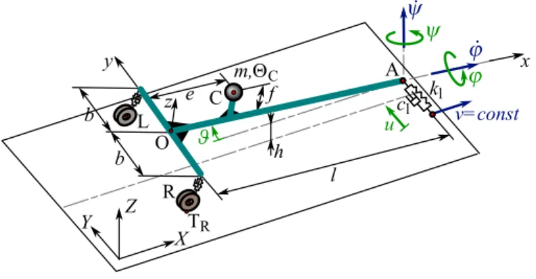
MECHANICAL MODEL AND GOVERNING EQUATIONS Figure 1 shows a spatial, 4 degrees-of-freedom (DoF) me- chanical model of towed two-wheeled trailers. The trailer is towed with a constant longitudinal speedvin theX direction at the king pin A. The ground-fixed coordinate system is denoted by (X,Y,Z), while(x,y,z)coordinate system is fixed to the trailer.
The vertical distance between the king pin A and the ground ish, the track width is 2band the caster length isl. The center of mass is positioned at point C whose position can be described with pa- rameterseand f. The mass of the trailer is denoted bymand the mass moment of inertia isJC. The center points of the right and the left wheels are denoted by R and L, while the contact points between the tires and the ground are marked by TRand TL. The overall stiffness and the damping of the wheel suspensions and the tires are described bykandc, respectively. A spring of stiff- nesskl and damper of damping factorcl are applied to support laterally the king pin at point A, which try to represent the effect of the towing vehicle.
X Y Z
C f
v=const e
m, C
L O
R TR b
b l
A
h
u
y x
z kl
cl
FIGURE 1. THE MECHANICAL MODEL OF TOWED TWO- WHEELED TRAILERS.
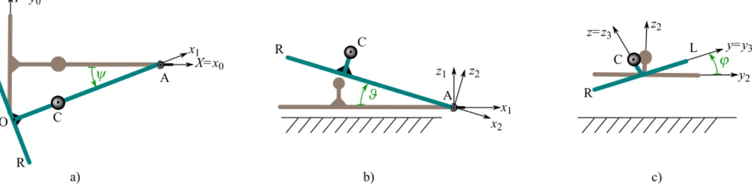
The system hasn=4 degrees of freedom, namely the mo- tion of the trailer can be described with the yaw angleψ, the pitch angleϑ, the roll angleϕand the lateral displacement of the king pinu. The illustration of the angles can be seen in Fig. 2, where the sequence of rotations are also given. Thus, the vector of the generalized coordinates is
q=
ψ ϑ ϕ uT
. (1)
Since the system is holonomic, i.e. there are only geometri- cal constraints, the equations of motion can be derived with the Lagrange equation of the second kind [8]:
d dt
∂T
∂q˙k−∂T
∂qk =Qk, k=1. . .n, (2)
whereT is the kinetic energy of the system,Qkis thekthcompo- nent of the generalized force andqk is thekthgeneralized coor- dinate. The kinetic energy of the system can be calculated as
T=1
2mvC2+1
2ωT·JC·ω. (3) The velocity of the towing point in the ground-fixed coordinate system is
vA= vu˙0T
(X,Y,Z), (4)
thus the velocity of the center of mass can be calculated by means of the reduction formula:
vC=vA+ω×rAC, (5) where the angular velocity of the trailer (in the trailer-fixed coor- dinate system) is
ω=
ϕ˙−ψ˙sinϑ ϑ˙cosϕ+ψ˙cosϑsinϕ ψ˙cosϑcosϕ−ϑ˙sinϕ
(x,y,z)
, (6)
and the position vector from point A to point C is rAC=
−l+e0 fT
(x,y,z). (7)
The mass moment of inertia matrix at point C is considered as
JC=
JC,x 0 0 0 JC,y 0 0 0 JC,z
(x,y,z)
=
(4b2+4f2)m
12 0 0
0 (4f212+l2)m 0 0 0 (4b212+l2)m
. (8) The generalized force can be obtained from the virtual power of the active forces, by collecting the coefficients of the virtual generalized velocities. The virtual power is
δP=G·δvC+FRtyre·δvTR+FRsusp·δvR+FLtyre·δvTL+ +FLsusp·δvL+FAlat·δvA, (9) whereGis the gravitational force;FRtyre andFLtyre are the tire forces acting at points TR and TL;FRsusp andFLsusp are the sus- pension forces acting on the chassis of the trailer at points R and
a) R
O L
C
A
X=x0 Y=y0
y1 x1
c) L
R C
z2
z=z3
y=y3
y2
b)
x1 x2
z2
z1
A R C
FIGURE 2. THE ILLUSTRATION OF THE YAW ANGLEψ, THE PITCH ANGLEϑ AND THE ROLL ANGLEϕ.
Z X Y
L C
R
A
G
x y
z
FR tyre,lat
TR elat
dR
FR tyre,z
FR susp dL
v=const FA lat
FL tyre,lat FL tyre,z
FL susp TL
FIGURE 3. THE ACTIVE FORCES ACTING ON THE TRAILER.
L; andFAlatis the lateral force acting at point A. The active forces are shown in Fig. 3.
The gravitational force can be calculated as G=
0 0−mgT
(X,Y,Z). (10)
The lateral tire forces can be obtained as FRtyre=FRtyre,lat·elat,
FLtyre=FLtyre,lat·elat, (11)
whereelatis the projection of the rotational axis of the wheelsy to the plane of the ground(X,Y), see Fig. 3. The magnitude of the lateral component of the tire forces is calculated in our study with the help of the so-called Pacejka’s Magic Formula [2]:
Ftyre,lat(α,Ftyre,z) =Dsin(Carctan(Bα−E(Bα−arctan(Bα))))
·Ftyre,z,
(12)
whereFtyre,zis the vertical load on the tire,Bis the stiffness fac- tor,Cis the shape factor,Dis the peak factor andE is the cur- vature factor. In this current study, the factors of Eqn. (12) were chosen for dry asphalt:B=10,C=1.9,D=1,E=0.97.
In order to analyze the rocking motion of the trailer, when the disengagements of the tires also happen, we have to con- sider that the vertical loadFtyre,zon a tire became zero. Namely, switches between piece-wise smooth formulas have to be in- cluded in the model. To handle this non-smooth nature of the describing equations, we use the following Heaviside function H(x):
H(x) =1 2
1+tanhx ε
, (13)
whereεis the smoothing parameter. The smallerεis, the more precise (sudden) the switching is. Hence we do not take into account the mass of the wheels, the vertical load on the tires can be calculated from the suspension forces:
FRsusp=
0 0FRsuspT (x,y,z), FLsusp=
0 0FLsuspT (x,y,z).
(14)
With the Heaviside function in Eqn. (13), the magnitude of the force arising in the suspension of the right wheel of the trailer can be calculated as
FR susp= ((LR,0−dR)k+ (vTR,z−vR,z)c)·H(LR,0−dR)
·H((LR,0−dR)k+ (vTR,z−vR,z)c), (15) where the parameter LR,0 is the free length of the spring,dR is the distance between points R and TR,vTR,zandvR,zare the com- ponents of the velocities in thezdirection. The criteria formu- lated in Eqn. (15) are based on the following assumptions. The
first Heaviside function guaranties that the suspension force can be non-zero if the spring is compressed. The second Heaviside function takes into consideration that the force generated by the damper can be negative but the normal force that acts on the tire cannot. The suspension force for the left wheel can be calculated similarly.
The lateral force acting at point A can be calculated as fol- lows:
FAlat=
0−klu−clu˙0T
(X,Y,Z). (16)
By substituting the forces and the velocities into the Lagrange equation of the second kind (2), the governing equations can be derived. The equations of motion can be written in the following form:
Mq¨+C=0, (17) where Mis the mass matrix and C is a vector containing the remaining parts of the equation including several non-linearities.
LINEAR STABILITY AND NUMERICAL BIFURCATION ANALYSES
The equations of motion can be linearised around the recti- linear motion which corresponds toq0=0, namely
ψ(t)≡ψ0=0, ϑ(t)≡ϑ0=0, ϕ(t)≡ϕ0=0, u(t)≡u0=0.
(18)
The free lengths of the right and the left springs in the suspen- sions are assumed to be equivalent, thusϕ(t)≡ϕ0=0 is fulfilled if we choose the free lengths of the springs to be
LR,0≡LL,0=h+mg(l−e)
2kl . (19)
Thus, the linearised equations of motion can be written as Mlinq¨+Clinq˙+Klinq=0, (20) whereMlinis the mass matrix, Clinis the damping matrix and Klinis the stiffness matrix of the linearised system:
Mlin=
JA,z 0 m f(l−e)−m(l−e)
0 JA,y 0 0
m f(l−e) 0 JA,x −m f
−m(l−e) 0 −m f m
, (21)
Clin=
C1l 0 −C1h −C1
0 2cl2 0 0
−C1h 0 2b2c+C1lh2 −C1lh
−C1 0 −C1lh cl+C1lh2
, (22)
Klin=
CFαC0 0 −C0 0
0 2kl2−mg f 0 0
−CFαlC0h 0 2kb2−mg f 0
−CFαlC0h 0 −Cl0 kl
, (23)
where
CFα=BCD (24)
is the so-called cornering stiffness, and we also introduce
C0=mg(l−e) and C1=CFαC0
v (25)
in order to shorten the formulas.
As it can be seen, the linearised system can be separated into two subsystems: one differential equation can be disjointed, namely the pitch motion can be analyzed alone (1 DoF subsys- tem), while the remaining equations are coupled (3 DoF sub- system). Thus, it can be concluded that the pitch motion does not affect linear stability. The stability of the rectilinear motion could be investigated by using the Routh-Hurwitz criteria. Un- fortunately, no closed form formula can be derived for the critical towing velocity value. But, the linear stability can be investigated numerically.
By means of numerical bifurcation analysis, the non-linear behaviour of the trailer is investigated with the help of aMatlab package called DDE Biftool[9]. During the analysis, the Hopf bifurcations corresponding to the linear stability boundaries were located and the branches of the emerging periodic solutions were followed.
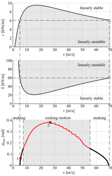
Figure 4 shows linear stability charts (the effect of the damp- ing and the stiffness of the suspension system and the tires on the linear stability) and the bifurcation diagram (the maximum am- plitude of the roll angleϕmax) versus of the towing speedv. On the linear stability charts, the light gray areas correspond to lin- early unstable, while the white areas correspond to linearly stable rectilinear motion. As it can be seen in the figure, the rectilin- ear motion is linearly unstable between approximately 5 m/s and 68 m/s forc=6 kNs/m andk=60 kN/m. It can be concluded that by increasing the value of the damping (or by decreasing the value of the stiffness), the linearly stable region grows. For these
0 10 20 30 40 50 60 70 v [m/s]
0 10 20 30 40 50 60 70
v [m/s]
0 10 20 30 40 50 60 70
v [m/s]
0 2 4 6 8 10
c [kNs/m]
20 40 60 80 100
k [kN/m]
0
0.1 0.2 0.3 0.4
0
linearly unstable linearly unstable
linearly stable linearly stable
rocking motion
snaking snaking
1.
2.
FIGURE 4. LINEAR STABILITY CHARTS AND BIFURCATION DIAGRAM BY MEANS OF THE TOWING VELOCITY.
parameter values, large amplitude rocking motion is present be- tween approximately 8 m/s and 55 m/s.
In the bifurcation diagram of Fig. 4, the light gray area cor- responds to the rocking motion. In the region where rocking mo- tion happens, the non-smooth nature of the vertical forces acting on the wheels has a strong effect, and numerical problems may occur during the continuation. As a result, sudden changes can be observed in the bifurcation branch. Since the detected periodic solutions shown in the figure are stable, the Hopf bifurcations are supercritical at the linear stability boundaries.
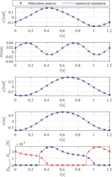
The bifurcation analysis results are validated by means of numerical simulations for two parameter points of Fig. 4. The time histories of the generalized coordinates and the vertical forces acting on the wheels are plotted for two different towing speed values: forv=6 m/s (snaking motion, see Fig. 5) and for
0 0.2 0.4 0.6 0.8 1 1.2
-0.1 0 0.1
bifurcation analysis numerical simulation
0 0.2 0.4 0.6 0.8 1 1.2
-0.04 -0.02 0 0.02 0.04
0 0.2 0.4 0.6 0.8 1 1.2
-0.2 0 0.2
0 0.2 0.4 0.6 0.8 1 1.2
-0.5 0 0.5
0 0.2 0.4 0.6 0.8 1 1.2
0 1 2
104
FIGURE 5. TIME HISTORIES OF THE GENERALIZED CO- ORDINATES AND THE VERTICAL FORCES ACTING ON THE WHEELS FORv=6 m/s (SNAKING MOTION).
v=27 m/s (rocking motion, see Fig. 6). The numerical simula- tion results are plotted with continuous blue and red lines, while the results of the numerical bifurcation analysis are drawn with crosses. As can be seen in Fig. 5 and 6, the results obtained by the two different methods are the same for both cases. The am- plitudes of the different quantities are significantly higher for the larger speed as was expected. Also, a sudden change can be ob- served in the time histories of the vertical forces in Fig. 6 due to the impacts of the tires.
0 0.2 0.4 0.6 0.8 1 1.2 -0.1
0 0.1
bifurcation analysis numerical simulation
0 0.2 0.4 0.6 0.8 1 1.2
-0.04 -0.02 0 0.02 0.04
0 0.2 0.4 0.6 0.8 1 1.2
-0.2 0 0.2
0 0.2 0.4 0.6 0.8 1 1.2
-0.5 0 0.5
0 0.2 0.4 0.6 0.8 1 1.2
0 1 2
104
FIGURE 6. TIME HISTORIES OF THE GENERALIZED CO- ORDINATES AND THE VERTICAL FORCES ACTING ON THE WHEELS FORv=27 m/s (ROCKING MOTION).
EXPERIMENTAL ANALYSIS
Based on the spatial, 4-DoF mechanical model, a small scale experimental rig was designed and manufactured. Since several parameters (for example the mass, the mass moment of inertia and the trail) can be modified on the experimental rig, the theo- retical and numerical results can be validated in the future.
The experimental setup can be seen in Fig. 7. The exper- imental rig is placed on a conveyor belt, whose speed can be modified between 0 m/s and 5 m/s. The lateral movement of the king pin is enabled by a roller bearing linear guide, while the lat-
FIGURE 7. EXPERIMENTAL SETUP.
0 0.01 0.02 0.03
v [m/s]
0 umax [m]
1 2 3
FIGURE 8. EXPERIMENTAL RESULTS: THE AMPLITUDE OF THE LATERAL DISPLACEMENT BY MEANS OF THE TOWING VELOCITY
eral stiffness is provided by a rubber band. The lateral stiffness can be modified by tightening and loosening the rubber band.
The position of the center of mass and the mass moment of in- ertia of the trailer can be tuned by the positioning of the dummy payload.
The speed of the conveyor belt and the lateral movement of the king pin were measured and the measurement data was evaluated inMatlab. First, only the vertical position of the center of mass was modified. Fig. 8 shows the amplitude of the lateral displacementumaxby means of the towing velocityvfor a certain parameter setup. As it can be observed, oscillation of the trailer appear above the critical speed atv≈0.8 m/s. First, the vibration amplitude strongly depends on the speed, namely, it increases significantly close to the critical speed. Abovev≈1.5 m/s, the amplitude of the vibrations is nearly constant.
The variation of the vibration amplitude close to the criti- cal speed does not confirm without any doubt that the Hopf bi- furcation is supercritical, i.e. stable periodic oscillation coexist with the linearly unstable rectilinear motion. Thus, the predic- tion made by the numerical bifurcation analysis cannot be clearly validated based on our experiments since the amplitudes of the vibrations change very rapidly aroundv≈0.8 m/s and we could not control the speed of the conveyor belt with such high accu- racy.
CONCLUSIONS
It can be established based on the numerical bifurcation analysis that the Hopf bifurcations related to the linear stability boundaries are supercritical. From an engineering point of view, this scenario is advantageous since perturbation in the linearly stable parameter domain cannot induce large amplitude nonlin- ear vibrations, which could lead to accidents.
The experimental test on small scale trailer partly confirmed the numerical results, but a more detailed experimental analy- sis, and the determination of the sense of bifurcations have to be future tasks.
ACKNOWLEDGMENT
This research was partly supported by the National Re- search, Development and Innovation Office under grant no.
NKFI-128422 and by the Higher Education Excellence Program of the Ministry of Human Capacities in the frame of Artificial intelligence research area of Budapest University of Technology and Economics (BME FIKP-MI).
REFERENCES
[1] Schlippe, B., and Dietrich, R., 1941. “Das Flattern Eines Bepneuten Rades (Shimmying of a pneumatic wheel)”.
In Bericht 140 der Lilienthal-Gesellschaft f¨ur Luftfahrt- forschung, pp. 35–45, 63–66. English translation is avail- able inNACA Technical Memorandum1365, pages 125-166, 217-228, 1954.
[2] Pacejka, H., 2002. Tyre and Vehicle Dynamics. Elsevier Butterworth-Heinemann.
[3] Sharp, R. S., Evangelou, S., and Limebeer, D. J. N., 2004.
“Advances in the modelling of motorcycle dynamics”.Multi- body System Dynamics, 12(3), pp. 251–283.
[4] Troger, H., and Zeman, K., 1984. “A nonlinear-analysis of the generic types of loss of stability of the steady-state motion of a tractor-semitrailer”. Vehicle System Dynamics, 13(4), pp. 161–172.
[5] Darling, J., Tilley, D., and Gao, B., 2009. “An experimen- tal investigation of car–trailer high-speed stability”. Pro- ceedings of the Institution of Mechanical Engineers, Part D:
Journal of Automobile Engineering, 223(4), pp. 471–484.
[6] Beregi, S., Takacs, D., Gyebroszki, G., and Stepan, G., 2019.
“Theoretical and experimental study on the nonlinear dy- namics of wheel-shimmy”. Nonlinear Dynamics, sep.
[7] Sharp, R. S., and Ferna´ndez, M. A. A., 2002. “Car-caravan snaking - part 1: the influence of pintle pin friction”. In Proceedings of the Institution of Mechanical Engineers Part C - Journal of Mechanical Engineering Science, Vol. 216 of 7, pp. 707–722.
[8] Gantmacher, F., 1975. Lectures in analytical mechanics.
MIR Publishers, Moscow.
[9] Engelborghs, K., Luzyanina, T., and Samaey, G., 2001.
DDE-BIFTOOL v. 2.00: a Matlab package for bifurcation analysis of delay differential equations. Department of Com- puter Science, K.U.Leuven.