PREFAB WATER TOWERS
FOR LOWER STORAGE CAPACITIES
Dr. Béla Csíki – Károly Kôszeghy
Due to the recent demand for water supply developments in Hungary two types of water towers made of prefabricated elements have been developed for lower storage capacities, from 50 m
3up to 750 m
3. The paper summarizes the design aspects and also the experiences obtained during the construction of five new water towers of various capacities in this range having been realized, so far. Although the application of steel towers in lower storage ranges has been regarded more typical, the realization of prefabricated concrete water towers has proved to be favourable and economic as well.
Keywords: water tower, prefabrication, prestressing, post tensioning, mast, tank, foundation cone.
1. INTRODUCTION
In connection with the recent water supply developments in the country two water tower types have been developed for lower water storage capacities in Hungary. The first type is applicable for 50 m3 to 100 m3, while the second type can be used from 150 m3 up to about 750 m3 storage capacities.
Both types are almost fully made of prefabricated reinforced concrete elements. Feasibility of the realization in a storage range frequently covered by steel towers is based on the following – for long time existing – prefabrication capacities of o circular pipe concrete elements widely used to build
underground conduits, and
o wall- and roof elements for prefab under surface circular basins often built for drinking water storage in the past few decades.
The idea of creating water towers by using such prefab reinforced elements was coming from the manufacturer of the elements itself, AGM Beton Zrt. (H-2200 Monor, Külterület, Hrsz.: 0100/8). The company playing an increasing role in the civil engineering execution market in Hungary and abroad was the main contractor of the execution of the five recently built water towers in Hungary, as well.
There are many examples for reinforced concrete water towers built by using prefabricated elements. In most cases the mast is erected monolithically using sliding shutter, while the tank is assembled on the land surface from prefab elements before lifting it up to its final position (Koperniczky, 1969). An alternative method is also widely used: cast in situ concreting of the tank on mounted shutter elements at the bottom surface before moving it up the tower (Kiss and Tóth, 1973). There are much fewer instances for prefabrication extending also to the mast of the water tower. An interesting example is a set of uniform 200 m3 water towers of such a kind in Italy, near Verona (Márkus, 1984). In addition to the tank also the mast of the towers was made of prefabricated elements connected by prestressing (post-tensioning). Mainly the mast prefabrication resulted in a very short (3 weeks/tower) building time of these towers often commemorated about. The present paper on the
issue is a re-edited version of a CCC congress presentation held in Hungary (Csíki, et al., 2017).
2. STRUCTURAL ARRANGEMENT
2.1 Tower shaping
Shaping of both tower types are based on putting together prefab pipe-, wall- and roof elements in order to get the superstructure - the mast and the tank, as well - of a water tower. The mast of both water tower types is made of vertically post-tensioned prefabricated reinforced concrete pipe elements.
The storage tanks above the mast are also fully prefabricated with watertight connections, but the arrangements are slightly different.
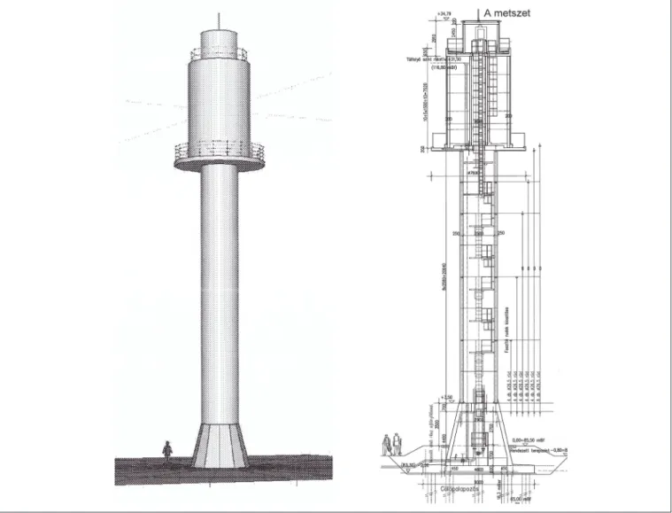
The design view and the vertical section of tower Type 1.
for lower (from 50 to 100 m3) capacities is shown in Fig.1.
Tower Type 2.is developed for a bit higher (from 150 to 750 m3) storage capacities, Fig.2.
The circular tank-wall of the first type for smaller capacities consists of cylindrical segment elements. The tank-wall of the second type for the bigger capacity is polygonal in layout, and consists of vertical plain panels. The only main structural part of both types made of in-situ reinforced concrete is the founding of the water-towers.
2.2 Substructure and foundation
The substructure consisting of a foundation slab and of a founding cone at both water tower types is made of in-situ (monolithic) reinforced concrete.
Depending on the soil conditions of the site plane- or piled foundation is applied. The foundation method determines the necessary layout measure of the applied (circular or polygonal) foundation slab. (A piled foundation may need less size in layout.)
The founding cone stiffening the substructure on the one hand secures the entrance of the tower, on the other hand serves
DOI: 10.32970/CS.2019.1.3
as anchoring space for the prestressing bars of the mast. The height of the cone is about 5 m, the diameter is changing from 3 m to 5 m. The thickness of the roof slab of the cone where the mast prestressing bars are fixed to is 0.7 m.
The applied grade of structural concrete for the substructure is C35/45-XC4-XF1-XA1, with a reinforcing steel category of B500B.
2.3 Prestressed mast
The mast of both tower types consists of prefabricated reinforced concrete pipe elements of 3.0 m outer diameter and of 250 mm wall thickness. The height of the pipe elements is 2.58 m. The number of the mast elements can be about 9 to 11 pieces depending on the required tower height. At tower Type 2 the last element is special to allow for anchoring radial cantilever beams directly supporting the tank.
The mast elements are gradually post-tensioned through the pipe-walls in vertical direction by prestressing bars anchored at the bottom of the thick roof of the founding cone. In the realized cases Dywidag prestressing bars (DSI 950/1050) of 26.5 and 32 mm diameter were used.
The applied grade of structural concrete for the mast elements is C50/60-XC4-XF1-16-F3, with reinforcing bars of B500B.
2.4 Tank supporting
The direct supporting of the tank at the top of the mast is different for the two tower types.
At Type 1. an in-situ prefabricated reinforced concrete circular plate is lifted and fixed directly to the final mast element. Then, the prefab segment elements of the tank are placed directly to the circular plate functioning as bottom plate of the tank.
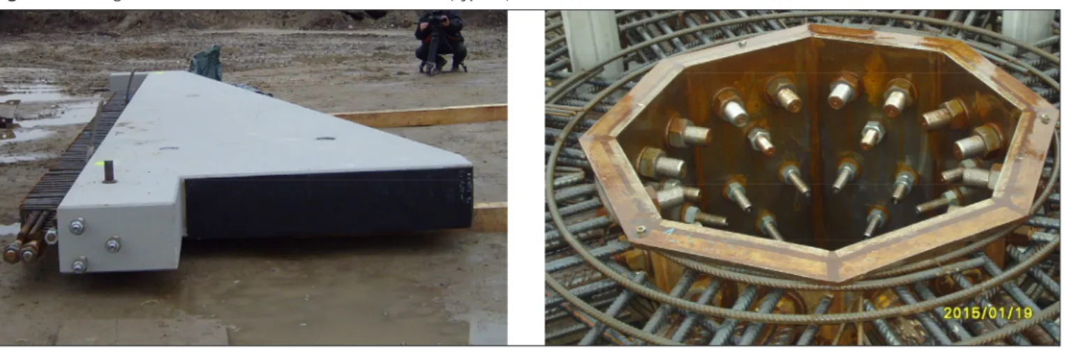
At Type 2. radially located, reinforced concrete cantilever beams are used for supporting the tank. The bottom plate is made of in-situ reinforced concrete casting on prefabricated shallow shutter slabs after they have been lifted up to the cantilevers. Fixing and anchoring of the radial prefabricated cantilevers to the specially arranged, final mast element was one of the most challenging questions to be solved during the design, Fig. 3.
2.5 Tank structures
The storage tanks above the mast are also fully prefabricated with watertight connections, but the arrangements of the sidewalls are slightly different, Fig.4. The effective layout of tanks for water storage is circular ring-shaped (not circle) because of a central circular pipe-element with a steel ladder inside connecting the mast area with the tank-roof to secure free access. This central pipe acts as an inner support of the tank-roof, as well.
The circular tank-wall of Type 1. for smaller capacities consists of prefabricated cylindrical segment elements of 200 mm thickness, and of 1.50 m height connected to form whole circles (rings) at the ground surface. Each ring including three connected segments is lifted up to the bottom plate on the mast
Fig. 1. Design view and section of tower Type 1
(or onto the previous full ring). A 100 m3 capacity tank is of 4.64 m diameter, with a 7.50 m necessary wall height. This height can be reached by five whole rings with four circumferential watertight connections worked up at their final location by special sticking material and welding.
The tank-wall of Type 2. for the bigger capacity is polygonal in layout. It consists of prefabricated vertical plain panels with horizontal and vertical stiffening ribs at the panel-edges. The panels are connected to each-other by bolts along the vertical ribs, while their bottom is welded to steel continuous profiles concreted in the bottom plate. The water-tightness at each
Fig. 2. Design view and section of tower Type 2.
junction is secured by cement-slurry injection of the designed gaps.
Regarding a 200 m3 storage capacity tank, 16 wall-panels of 1.76 m width are needed, arranged around a 9.16 m diameter inner circle of the 16 sides polygon. The height of the panels is 4.60 m, with lowest thickness of 150 mm. (Tanks of similar arrangement with several measures were widely used in Hungary to build underground water reservoirs a few decades ago.)
The grade of structural concrete to the prefab elements of the water tanks is C40/50-XV2(H)-XC2-XD2. The category of the applied reinforcing steel is B500B.
Fig. 3. Anchoring of radial cantilevers to the final mast element (Type 2.)
2.6 Mast and tank element joints
The circular horizontal joints of the mast elements are formed by smooth surfaces (without any notches) compacted by sticking and – obviously – by the prestressing itself.
The watertight joints of tank elements of both Types at the bottom slab are formed by mixing of in-situ welding and concreting. The wall to wall circumferential joints at tank of Type 1. are notched connections compacted by sticking and welding. The vertical joints along the wall elements of Type 2.
are bolted and in-situ cement injected connections.
3. STRUCTURAL ANALYSIS
The following structural models, design principles and analysis methods were applied to the structural design of the water towers:
• In general:
Three-dimensional combined structural model on elastic bedding or on discrete elastic springs examined by FEM (Fig. 5).
Fig. 4. Tank horizontal sections (Type 1 left, Type 2 right)
• To earthquake load (Modal response spectrum analysis):
1. Static model: Reduced at the mass centre (one mass) vertical cantilever. The water load (weight) is considered in the metacentre when determining the mass centre.
2. Dynamic model: Two mass (M1, M2) vertical cantilever.
M1 is the sum of the mass of the tower and of the mass of the impulsive water part (moving together with the structure) acting in the mass centre. M2 is the mass of convective water part (moving separately from the structure) suspended in the metacentre.
• To stability analysis:
Elastically supported (walled in) vertical cantilever. (The critical force based on Föppl-Papkovics principle.)
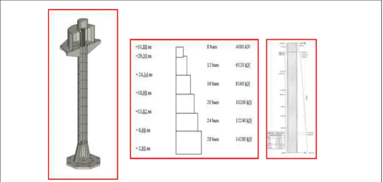
• Prestressing of the mast:
The effective (applied in two steps) prestressing forces of the mast are increasing from top to bottom to eliminate tension stresses along the mast. The distribution of the considered prestressing forces and of the normal forces due to an ultimate load combination of 200 m3 water tower in Gádoros (Hungary) is presented in Fig. 5.
Fig. 5. FEM model of structure, Prestressing- and axial forces of mast
4. CONSTRUCTION ASPECTS, FEASIBILITY OF APPLICATION
To satisfy a recent demand for high water storage of lower range capacity, five new type almost fully prefabricated reinforced concrete water towers have already been built, in Hungary. Three of the first type with 100 m3 storage capacity were built and put in operation in Árpádhalom, Eperjes and Újiráz in 2015. Two of the second type have been built so far:
one of 200 m3 capacity in Gádoros in 2015, and one of 500 m3 capacity in Dömsöd in 2014.
The prefabrication of the elements and the leading of the in situ construction works for all the new towers were done by AGM Beton Zrt. (H-2200 Monor, Külterület, Hrsz.: 0100/8, Hungary). Advantages regarding the construction time and cost effectiveness of building almost fully prefabricated reinforced concrete towers have proved to be considerable because of the following reasons:
o There has been, for long time, a prefabrication capacity for reinforced concrete elements applicable (by not much modification) to build mast and tank of water towers.
o There have been, for long time, building experiences of prefabricated water reservoirs on or under the ground.
o The mounting-like building activity needs low living labour capacity (Fig. 6).
o Possibility of more tower construction at the same time with not multiple recourses. This may reduce multiple costs.
o Possibility of very short building time. After the in-situ
Fig. 6. Examples for mounting-like construction (Type 2)
concreting works of the substructure have been done the building time of mounting is not more than a few weeks.
5. CONCLUSIONS
Two types of water towers almost fully made of prefabricated elements have been developed for lower ranges of water storage capacity, recently. The first can be used for 50 m3 to 100 m3, while the second type is applicable from 150 m3 up to 750 m3 storage capacities. The design aspects and also the experiences obtained during the recent erection of five new type water towers have been summarized in the paper.
Realization of the water towers proved to be economic due to the short time of in-situ building works and also to the (for long time) existing prefabrication capacity. The experiences have been positive so far regarding the operation aspects of the towers as well.
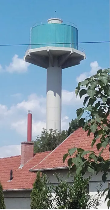
Hopefully, the new civil engineering structures, as special kinds of landmarks, satisfy the aesthetic considerations, as well, Fig.7.
6. ACKNOWLEDGEMENTS
The authors must express their thanks to AGM Beton Zrt. (H- 2200 Monor, Külterület, Hrsz.:
0100/8, Hungary), the general contractor of the towers for the possibility of taking part in the development and design of the new type civil engineering structures.
Fig. 7. Views of the water tower types (Type 1 left, Type 2 right)
Special thanks to Gábor Szilágyi, general manager of the company and to his colleagues, who were taking part in the detailing of the structural design.
7. REFERENCES
Csíki, B., Kőszeghy, K., Perczel, Z. (2017), “New Type Prefabricated Water Towers with Prestressed Mast”, Proceedings of CCC 2017, Tokaj, Hungary, September 2017, pp. 15-22.
Kiss, I., Tóth, L. (1973), “Water tower of Balaton Youth-town”, Műszaki Tervezés, (in Hungarian) March 1973, pp. 27-29.
Koperniczky, J. (1969), “Construction of small water towers”, Műszaki Tervezés, (in Hungarian) March 1969, pp. 19-22.
Márkus, G. (1984), “Reinforced concrete reservoirs”, Mérnöki Kézikönyv, II., (in Hungarian) 1984, pp. 920-942.
Dr. Béla CSÍKI (1957), MSc (1982), Doctorate (1993), Civil Eng., TU Budapest. MSc Real Estate (2002), NTU Nottingham. Employments: DCB Engineering Ltd., managing director (2003- ), E&H Ltd., technical director (2016- ). He is a member of the editorial board. His main field of interest is dealing with specific structural problems of and also the design of special civil engineering structures mainly in connection with water and waste water treatment or industrial fields. He has been author of several papers on his professional activity.
Károly KŐSZEGHY (1944), MSc (1970), Civil Eng., TU Budapest. From 1970 he worked for more than two decades for company named Mélyépterv dealing with and leading the design of substantial civil and structural engineering structures at the time. Since 1993 he has been working for his own company, Kőszeghy Ltd. His professional work covers several fields of structural engineering in Hungary and abroad, such as: developments in prefabrication for civil engineering, design of special structures, sludge digesters, reservoirs, towers, industrial buildings, etc. Several studies and papers commemorate his specialties.