DOI: 10.1556/606.2019.14.2.15 Vol. 14, No. 2, pp. 169–180 (2019) www.akademiai.com
BUCKLING ANALYSIS OF RECTANGULAR PLATES WITH CENTERED CUT-OUT SUBJECTED
TO IN-PLANE TWO DIRECTIONS UNDER DIFFERENT BOUNDARY CONDITIONS
1 Ahmed EL BOUHMIDI, 2 Mohamed ROUGUI*, 3 Ouadia MOUHAT
1,2,3
Laboratory of Civil Engineering and Environmental, High School of Technology Salé Mohammed V University in Rabat, Morocco
e-mail: 1abouhmidi@gmail.com, 2rougui93@yahoo.fr, 3ouadie.mouhat@gmail.com Received 18 July 2018; accepted 18 January 2019
Abstract: In this research, buckling behavior of rectangular plates of symmetric and anti- symmetric laminated composite having centered circular hole under in-plane static loadings is analyzed with the aid of first shear deformation theory and the finite element method is used to find critical loads. The presence of hole may cause redistribution of stresses in plates with reduction of stability. The aim of the current paper is to find critical buckling load. The loads depend on many parameters like geometric aspect ratios (a/b) and (d/b), plate thickness (t), diameter of the circular hole (d), orientation of ply and boundary conditions. Numerical simulations for various boundary conditions obtained are shown in tables and graphical forms and compared with each other.
Keywords: Laminated composite, Buckling, Finite element, Boundary conditions
1. Introduction
Laminated composite plates are widely used in many engineering structures including automotive bridges wind-turbine blades and aviation, due to their lower weights compared to metal structures. Frequently, such plates contain holes of various shapes, for example for access or for weight savings and this perforation or openings often require some type of reinforcing structure to control local structural deformations and stresses near the cutout. In addition, these structures may experience compression loads during operation, and thus their buckling response characteristics must be
*
understood and accurately predicted in order to determine effective designs and safe operating conditions for these structures. Thus in the design context buckling analysis plays a crucial role.
Buckling of rectangular plates it loss of stability [1] and it was widely discussed in literature, Reza Eslami [2], Timoshenko and Gere [3], Waszczyszyn et al. [4]. The existence of analytical solutions for certain special cases of loads and boundary conditions creates a good basis examination of numerical results Wang at al. [5]. Hence, the analytical buckling solutions are inaccessible, and various numerical methods need to be developed for analyzing these types of plates. In the literature, few published studies investigated the buckling of laminated composite plates with a cutout [6], [7].
Lin and Kuo [6] presented a nine-node Lagrangian finite element analysis for the buckling of cross-ply and angle-ply-laminated plates with circular holes under in-plane static loadings. Altan and Kartal [7] also used the finite element approach for investigating the buckling of reinforced concrete plates with central rectangular hole.
Schlack investigated the elastic stability of pierced square plates by analytical method and experimental [8], [9]. Falkowicz and Dębski [10] studied numerical and experimental stability of rectangular plate with rectangular cut-out. Mouhat and et al.
[11], [12] studied dynamical buckling rectangular stiffened plates with geometric imperfection and effect of pulse duration.
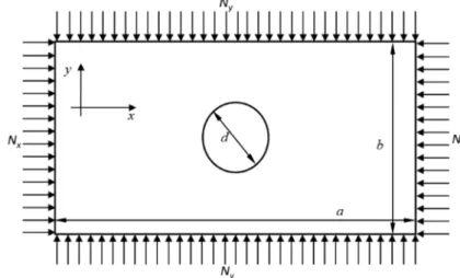
This paper deals with buckling of symmetrically and anti-symmetrically laminated composite plates with circular hole under biaxial static loadings, Fig. 1. The First Shear Deformation Theory (FSDT) plate deformation theory and the variational energy method are employed in mathematical formulation, and the finite element technique is used for finding critical loads. The effects on critical load by whole size, plate thickness ratio, material modulus ratio, ply-lamination geometry, loading types, and boundary conditions are investigated. The results are shown in the graphical form for various boundary conditions.
Fig. 1. Rectangular plate under biaxial compressive load (Nx = −N0 andNy = −ξN0)
2. Theoretical background
2.1. Kinematics
Consider a symmetrically or anti-symmetrically laminated rectangular plate of length a, width b, central circular hole of diameter d and thickness t which consists of six orthotropic laminas and fibers orientation [(90°/+θ/-θ)]sym for symmetric and [(90°/+θ/-θ)]asym for anti-symmetric.
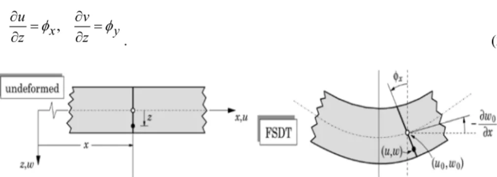
The displacement field according to the FSDT can be expressed in the form [13], Fig. 2:
( ) ( ) ( )
( ) ( ) ( )
(
, ,) ( )
, ,, , ,
, ,
, , ,
, ,
0 0 0
y x w z y x w
y z z y x v z y x v
y z z y x u z y x u
y x
= +
=
+
=
φ φ
(1)
where u0
( )
x,y,v0( )
x,y, w0( )
x,y denote the displacements of a point on the plane 0z= , and φx and φy are the rotations of a transverse normal about the y and x axes, respectively, Fig. 2,
y
x z
v z
u φ =φ
∂
= ∂
∂
∂ ,
. (2)
Fig. 2. Deformation of a transverse normal according to first shear deformation plate theory The strains associated with the displacement field (1) are given by
, ,
0 0
z y y v
z x x u
y yy
xx x
∂ + ∂
∂
=∂
∂ + ∂
∂
=∂
ε φ ε φ
(3a)
. 0 ,
,
,
0 0
0 0 0 0
=
∂ +
=∂
∂ +
=∂
∂ +∂
∂ + ∂
∂
∂
∂ +∂
∂ +∂
∂
= ∂
zz y yz
x xz
x y xy
y w x
w
x z y
y w x w x v y u
ε φ γ
φ γ
φ φ γ
(3b)
The constitutive equation for an orthotropic layer can be expressed by [14]
. ,
55 45
45 44
66 26 16
26 22 12
16 12 11
=
=
xz yz xz
yz
xy yy xx
xy yy xx
Q Q
Q Q
Q Q Q
Q Q Q
Q Q Q
γ γ τ
τ
γ ε ε
τ σ σ
(4)
The resulting forces and moments occurred in the plate are obtained by integrating the stresses through the thickness of laminas [6], [7].
[ ]
∑ ∫[ ]
∫ =
=
− = −
n i
i t
xy yy xx t
t xy yy xx
xy xy
yy yy
xx xx
dz z dz
z M
N M N
M N
1 i 2
/ 2 /
1 1
1 τ σ σ
τ σ σ
, (5)
and the shear forces to the shear strains can be computed as:
∑ ∫
=
∫
=
− = −
n i
i
t xz
yz s
t
t xz
yz s
xz
yz k dz k dz
R R
1 i 2
/ 2
/ 1 τ
τ τ
τ
, (6)
where kS( 5 6)= is the shear correction factor [15], [16].
For the buckling analysis, the in-plane compression edge forces are assumed the only applied loads (Fig. 1), defined by:
0
0, N N
N
Nx =− y =−ξ . (7)
The equation set that solves the buckling problem takes the form:
=0
∂ − + ∂
∂
∂
xy
xx xy R
y M x
M , (8a)
=0
∂ − +∂
∂
∂
yz
xx xy R
y M x
M , (8b)
2 0 2 2 2
0 =
∂
− ∂
∂
− ∂
∂ +∂
∂
∂
xy
xz yz R
y w x
N w y R x
R ξ . (8c)
2.2. Finite element model
The total potential energy Π of a laminated plate under biaxial loadings is equal to strain energy U can be written as [4], [17], [18]:
V U Ub+ s+
Π = , (9)
where Ub is bending term, Us is the strain energy of shear and V denotes the potential energy of in-plane forces.
The equilibrium requires that the potential energy Π must be stationary. The equilibrium equations of the cross-ply laminated plate can be derived from the variational principle by using
=0 Π
δ . (10)
The finite element method is applied in this study; the following linear algebraic equations are obtained by using equations (8), (9) and (10):
[ ] [ ]
(
K +λKG) [ ]
U =0, (11)where [K] is the stiffness matrix, [KG] is the geometric stiffness matrix, λ is the eigenvalue and [U] is the nodal displacements. The critical buckling load Nx,cr is that which corresponds to the least eigenvalue λ determined by:
[ ] [ ]
( )
0det K +λKG = , (12)
and the stiffness components is based on the following 13 weighted-residual statements of the FSDT [19] and [20]:
( )
01 1
1 − ∫ + =
∫
∂ +∂
∂
∂
e e
ds N n N n W dxdy y N
N W x W
xy y xx x xy
xx Γ
Ω ,
( )
02 2
2 − ∫ + =
∫
∂ +∂
∂
∂
e e
ds N n N n W dxdy y N
N W x W
yy y xy x yy
xy Γ
Ω ,
, 0 0
0 0
3 0
0 0
3 0 0
3
∫ =
∂ + ∂
∂ + ∂
+
∂ + ∂
∂ + ∂ +
∫
∂ + ∂
∂
∂
∂ +∂
∂ + ∂
∂
∂
∂
∂
e e
ds y n
N w x N w R y n
N w x N w R W
y dxdy N w
x N w y W y N w x N w x W
y yy
xy yz x xy
xx xz
yy xy
xy xx
Γ Ω
( )
04 4 4
4 + ∫ + =
∫
+
∂ +∂
∂
∂
e e
ds n M n M W dxdy R
W y M
M W x W
y xy x xx xz
xy
xx Γ
Ω
,
( )
05 5 5
5 + ∫ + =
∫
+
∂ +∂
∂
∂
e e
ds n M n M W dxdy R
W y M
M W x W
y yy x xy yz
yy
xy Γ
Ω
,
0 0 12*
11*
6 =
∫
∂ +∂
−
− e
x dxdy N u
A N A
W xx yy
Ω
, (13)
0 0
*22 12*
7 =
∫
∂ +∂
−
− e
x dxdy N v
A N A
W xx yy
Ω
,
0 0 0 0
* 0 66
8 =
∫
∂
∂
∂ +∂
∂ +∂
∂ +∂
− e
y dxdy w x w x v y N u A
W xy
Ω
,
0 0
9 55 =
∫
+
∂ +∂
−
e
x dxdy w A k
W R x
s xz
Ω φ ,
0 0 44
10 =
∫
+
∂ +∂
−
e
y dxdy w A k
W R y
s yz Ω
φ ,
* 0
* 12 11
11 =
∫
∂ +∂
−
− e
x dxdy M
D M D
W xx yy x
Ω
φ ,
* 0
* 22 12
12 =
∫
∂ +∂
−
−
e
y dxdy M
D M D
W xx yy y
Ω
φ
,
* 0 66
13 =
∫
∂ +∂
∂ +∂
−
e
x dxdy M y
D
W xy x y
Ω
φ φ
,
where Ωe and Γe denote the element region and its boundary, respectively.
3. Results and discussion
The numerical simulations and appropriate calculations have been conducted using the finite element software ANSYS [21], [22]. The finite element SHELL181 has been used for discretization of created multi–layered composite plate model (Fig. 3). This is four nodes element with six degrees of freedom at each. It is suitable for analyzing geometrically nonlinear problems and modeling of different material properties. Its option Shell Section Type gives a possibility of defining a multi-layered cross-section, their thickness, number of integration points across each layer thickness and of introducing different material properties for separate layer. This approach of modeling orthotropic plate as multi-layered one is common in Finite Element Method (FEM) buckling analysis [7] and [18].
Fig. 3. SHELL 181 element geometry [22]
The composite laminated plates were analysed under three boundary conditions:
• Simple-Simple-Simple-Simple (SSSS)
( ) ( )
( ) ( )
( ) ( )
( )
, 0,( )
, 0, ,, 0 0 , ,
0 0 , , 0
, 0 , ,
0 , ,
, 0 , 0 ,
0 , 0 , 0
=
=
=
=
=
=
=
=
=
=
=
=
b x M b
x w b y
x M x
w y
y a M y
a w a x
y M y
w x
xx xx xx xx
(14)
• Simple-Simple-Simple-Free (SSSF)
( ) ( )
( )
, 0,(
4)
0, ,, 0 0 , ,
0 0 , , 0
2 3 66 3 12
3
22 =
∂
∂ + ∂
∂ +
= ∂
=
=
=
=
y x D w y D
D w b
x M b y
x M x
w y
yy
yy
(15)
• Simple-Clamped-Simple-Free (SCSF)
( )
( )
, 0,(
4)
0. ,, 0 ,
0 0 , , 0
2 3 66 3 12
3
22 =
∂
∂ + ∂
∂ +
= ∂
=
∂ =
= ∂
=
y x D w y D
D w b
x M b y
y x w
w y
yy
(16)
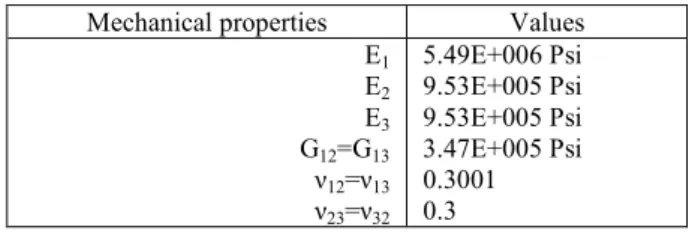
The mechanical properties of material used in this study are given in Table I.
Table I
Mechanical Properties of the laminated plate in E-Glass/Epoxy Mechanical properties Values
E1 E2
E3
G12=G13
ν12=ν13 ν23=ν32
5.49E+006 Psi 9.53E+005 Psi 9.53E+005 Psi 3.47E+005 Psi 0.3001 0.3
Results obtained are shown in Table II, Table III and Table IV.
Table II
Critical buckling load of the laminated plates of [(90°/+θ/-θ)]sym and [(90°/+θ/-θ)]asym under the boundary conditions Simple-Simple-Simple-Simple (SSSS)
Plate dimensions (in)
Nx,cr (kpsi)
Symmetric Anti-Symmetric
a b t d 15° 30° 45° 60° 15° 30° 45° 60°
6 6
0.23 0.312
1.132 1.403 1.845 2.8
1.19 1.49 1.927
2.89 1.25 1.569 1.987 2.902
1.25 1.567 1.949 2.766
1.13 1.383 1.826 2.746
1.195 1.467 1.911 2.824
1.256 1.549 1.98 2.848
1.24 1.538 1.933 2.719 5
4 3 6
0.3
2.471 3.054 3.983 5.974
2.588 3.23 4.153 6.164
2.717 3.399 4.277 6.189
2.71 3.387 4.187 5.8964
2.46 2.997 3.931 5.845
2.597 3.174 4.108 6.003
2.728 3.350 4.256 6.069
2.695 3.324 4.152 5.803 5
4 3 6
0.355 4.023 4.952 6.441 9.566
4.215 5.246 6.707 9.86
4.42 5.52 6.906 9.908
4.405 5.488 6.754 9.448
4.006 4.86 6.34 9.326
4.224 5.141 6.614 9.567
4.437 5.428 6.858 9.701
4.377 5.386 6.69 9.302 5
4 3
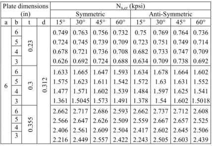
Table III
Critical buckling load of the laminated plates of [(90°/+θ/-θ)]sym and [(90°/+θ/-θ)]asym under the boundary conditions Simple-Simple-Simple-Free (SSSF)
Plate dimensions (in)
Nx,cr (kpsi)
Symmetric Anti-Symmetric
a b t d 15° 30° 45° 60° 15° 30° 45° 60°
6 6
0.23 0.312
0.749 0.724 0.678 0.626
0.763 0.745 0.721 0.692
0.756 0.739 0.736 0.724
0.732 0.709 0.708 0.688
0.75 0.723 0.682 0.634
0.769 0.751 0.733 0.709
0.764 0.749 0.747 0.738
0.736 0.714 0.709 0.692 5
4 3 6
0.3
1.633 1.575 1.477 1.361
1.665 1.623 1.571 1.5045
1.647 1.611 1.602 1.573
1.593 1.542 1.539 1.491
1.634 1.572 1.484 1.378
1.678 1.63 1.597
1.54 1.664 1.631 1.625 1.602
1.602 1.552 1.541 1.5018 5
4 3 6
0.355
2.662 2.566 2.406 2.216
2.717 2.647 2.561 2.449
2.686 2.626 2.609 2.557
2.593 2.509 2.504 2.422
2.662 2.559 2.417 2.243
2.737 2.667 2.602 2.505
2.712 2.657 2.645 2.603
2.608 2.525 2.506 2.439 5
4 3
Table IV
Critical buckling load of the laminated plates of [(90°/+θ/-θ)]sym and [(90°/+θ/-θ)]asym under the boundary conditions Simple-Clamped-Simple-Free (SCSF)
Plate dimensions (in)
Nx,cr (kpsi)
Symmetric Anti-Symmetric
a b t d 15° 30° 45° 60° 15° 30° 45° 60°
6 6
0.23 0.312
0.792 0.804 0.84 0.992
0.816 0.829 0.879 1.038
0.804 0.812 0.864 1.012
0.769 0.762 0.848 0.911
0.795 0.801 0.839 0.989
0.827 0.835 0.886 1.039
0.816 0.819 0.869 1.0131
0.745 0.763 0.867 0.911 5
4 3 6
0.3
1.723 1.745 1.825 2.147
1.778 1.805 1.909 2.247
1.752 1.765 1.876 2.186
1.671 1.653 1.734 1.968
1.729 1.739 1.822 2.141
1.799 1.814 1.922 2.248
1.775 1.779 1.886 2.188
1.683 1.657 1.729 1.968 5
4 3 6
0.355
2.806 2.839 2.968 3.485
2.897 2.938 3.106 3.642
2.887 2.873 3.048 3.541
2.717 2.685 2.816 3.188
2.814 2.826 2.961 3.473
2.929 2.949 3.124 3.642
2.887 2.892 3.063 3.542
2.735 2.692 2.808 3.187 5
4 3
It is easily seemed from Tables that while thickness increase the critical buckling load Nx,cr increase. Fig. 4 refers that critical buckling of the boundary condition (SSSS) plates are approximately 2 times greater than the buckling load of (SSSF) and (SCSF)
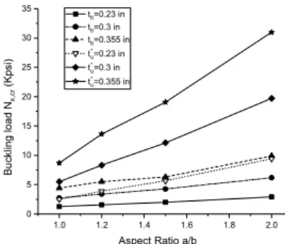
plates. The effects of a/b ratio on buckling load are illustrated in Fig. 5, according to it the buckling loads increase with increasing of a/b ratios. Furthermore, the highest values of buckling loads are calculated [(90°/60°/-60°)]sym (SSSS) plates, while the lower values are computed angle-ply [(90°/+θ/-θ)]sym (SSSF) plates. The effects of ply orientation symmetric and anti-symmetric on the buckling load can be seen in Table II, Table III and Table IV. The results show that the change in buckling load is neglected.
The effect of circular cut-out is taken into account. The analysis indicates that the variation of the buckling loads is very sensitive to the presence of hole. It can be seen that the buckling load generally decreases with presence of cut-out (Fig. 5), the predicted buckling loads of plates without hole is 70% higher than with hole in (SSSS) plates and 57% in (SSSF) plate and 67% in (SCSF) plate.
In Fig. 6, effects of hole size on critical buckling loads of rectangular orthotropic plates under biaxial compressions are compared with those obtained by El Youbi et al.
[18]. It can be seen that in dashed circle (Fig. 6), that the influence of hole is more significant for thinner plate t=0.23 in.
Fig. 4. Variation of the critical buckling load Nx,cr compared to the fibers orientation symmetric and anti-symmetric of a plate 6x4 in2 for thicknesses t=0.23 in and t=0.355 in
Fig. 5. Variation of the critical buckling load Nx,cr in function of aspect ratio a/b of biaxial plate compression (tb) compared to uniaxial load plate(tu)
15° 30° 45° 60°
0.6 0.8 1.0 1.2 1.4 1.6 1.8 2.0
Buckling load Nx,cr (Kpsi)
Fibers orientation, t=0.23 in SSSSS SSSFS SCSFS SSSSAS SSSFAS SCSFAS
15° 30° 45° 60°
2 3 4 5 6 7
Buckling load Nx,cr (Kpsi)
Fibers orientation, t=0.355 in SSSSS SSSFS SCSFS SSSSAS SSSFAS SCSFAS
1.0 1.2 1.4 1.6 1.8 2.0
0 5 10 15 20 25 30 35
Buckling load Nx,cr (Kpsi)
Aspect Ratio a/b tb=0.23 in tb=0.3 in tb=0.355 in t*u=0.23 in t*u=0.3 in t*u=0.355 in
Fig. 6. Hole effect on critical load of [(90°/+θ/-θ)]sym cross-ply under boundary conditions (SSSS) at different thickness ratio a/b under biaxial compression, Nx* is the critical load of plate without
hole [18]
4. Conclusion
In this study, the buckling load of E-Glass/Epoxy composite laminated rectangular plate with central circular cut-out bi-axially loaded is investigated. Additionally, the effect of a/b and t/b ratios on buckling loads are calculated. Solutions were done with FEM using ANSYS finite element program. From the present study, the following conclusions can be made:
1. The reduction of the buckling load due to hole is found to be significant, this means big holes cause the weakest plates under the pressure;
2. The increasing of buckling loads by increasing a/b ratios;
3. Boundary conditions of composite have the strongest effect on the buckling load, among the other parameters;
4. Buckling is loss of stability due to geometric effects and boundary conditions than the material failure;
5. The cross-ply [(90°/45°/-45°)]sym composite plates is stronger than other analyzed angle-ply laminated plates;
6. The [(90°/15°/-15°)]sym laminated plate is the weakest angle-ply plate;
7. From this study, no big difference between the cross-ply and angle-ply laminates with symmetric arrangement and anti-symmetric arrangement of layers.
Comparison of results of the finite element with experimental test has to be done.
References
[1] Vető D., Sajtos I. Application of geometric method to determine the buckling load of spherical shells, Pollack Periodica, Vol. 4, No. 2, 2009, pp. 123‒134.
[2] Reza E. M. Buckling and postbuckling of beams plates and shells, Springer, 2017.
[3] Timoshenko S. P., Gere J. M. Theory of elastic stability, McGraw-Hill, 1965.
0.05 0.06 0.07 0.08 0.09 0.10 0.11
0.30 0.35 0.40 0.45 0.50 0.55
Nx,cr/N*x
Aspect Ratio d/b, t=0.23 in (90°/15°/-15°)S (90°/30°/-30°)S (90°/45°/-45°)S (90°/60°/-60°)S
0.05 0.06 0.07 0.08 0.09 0.10 0.11
0.25 0.30 0.35 0.40 0.45 0.50 0.55
Nx,cr/N*x
Aspect Ratio d/b, t=0.355 in (90°/15°/-15°)S (90°/30°/-30°)S (90°/45°/-45°)S (90°/60°/-60°)S
[4] Waszczyszyn Z., Cichon C., Radwanska M., Stability of structures by finite element methods, Elsevier, 1994.
[5] Wang C. M., Wang C. Y., Reddy J. N. Exact solutions for buckling of structural members, Chemical Rubber Company Press, Boca Raton, Florida, 2005.
[6] Lin C. C., Kuo C. S. Buckling of laminated plates with holes, J. Comp. Mat. Vol. 23, No. 6, 1989, pp. 536‒553.
[7] Altan M. F., Kartal M. E. Investigation of buckling behavior of laminated reinforced concrete plates with central rectangular hole using finite element method, Mat. Desg.
Vol. 30, No. 6, 2009, pp. 2243‒2249.
[8] Shlack A. L. Jr. Elastic stability of pierced square plates, Exp. Mech. Vol. 4, No. 6, 1964, pp. 167‒172.
[9] Shlack A. L. Jr. Experimental critical loads for perforated square plates, Exp. Mech. Vol. 8, No. 2, 1968, pp. 69‒74.
[10] Falkowicz K., Dębski H. Numerical and experimental analysis of compression plate with cut-out, Mechanics and Mechanical Engineering, Vol. 20, No. 2, 2016, pp. 167‒175.
[11] Mouhat O., Khamlichi A., Limam A. Effect of pulse duration and shape on dynamic buckling of stiffened panels, Pollack Periodica, Vol. 11, No. 1, 2016, pp. 13‒24.
[12] Mouhat O., Khamlichi A., Limam A. Assessing buckling strength of stiffned plates as affected by localized initial geometric imperfections, Int. Rev. Appl. Sci. Eng. Vol. 4, No. 2, 2013, pp. 97‒103.
[13] Reddy J. N. Mechanics of laminated composite: Plates and shells, theory and analysis, Chemical Rubber Company Press, Boca Raton, Florida, 2004.
[14] Berthelot J. M. Composite materials: Mechanical behavior and structural analysis, Springer-Verlag, New York, 1999.
[15] Gruttmann F., Wagner W. Shear correction factors for layered plates and shells, Comput.
Mech. Vol. 59, No. 1, 2017, pp. 129‒146.
[16] Vlachoutsis S. Shear correction factors for plates and shells, Int. J. for Num. Meth. in Eng.
Vol. 33, No. 7, 1992, pp. 1537‒1552.
[17] Bolotin V. V. The dynamic stability of elastic systems, Holden-Day, San Francisco, 1964.
[18] El Youbi M., Rougui M., Tbatou T. A parametric study of the effects of instability for thin composite structures by the finite element method: buckling of FRP plates, J. Mater.
Environ. Sci. Vol. 6, No. 8, 2015, pp. 2198‒2205.
[19] Farshad M. Stability of structures, Elsevier, Amsterdam, 1994.
[20] Monteiro J. I. L., Daros C. H. Buckling analysis of laminated anisotropic Kirchhoff’s plates via the boundary element method, Lat. Amer. J. Sol. Stru. Vol. 15, No. 10, 2018, pp. 1‒23.
[21] Madenci E., Guven I. The finite element method and applications in engineering using ANSYS, Springer, New York, 2015.
[22] ANSYS mechanical APDL theory reference, Release 17.1, 2016.
![Fig. 3. SHELL 181 element geometry [22]](https://thumb-eu.123doks.com/thumbv2/9dokorg/1074493.71946/7.892.204.560.418.688/fig-shell-element-geometry.webp)
![Fig. 6. Hole effect on critical load of [(90°/+θ/-θ)] sym cross-ply under boundary conditions (SSSS) at different thickness ratio a/b under biaxial compression, N x * is the critical load of plate without](https://thumb-eu.123doks.com/thumbv2/9dokorg/1074493.71946/11.892.175.652.206.386/critical-boundary-conditions-different-thickness-biaxial-compression-critical.webp)
