Abstract
In our study, we dealt with the agricultural materials and waste to which the pyrolisis process is applicable, as part of a CHP pyrolisis power plant. We introduce the processes of planning, actualisation, and preceding experiments. We finish the study with introducing the experiences gathered from analysing the designed and manufactured prototype machinery. We hope that the solution will be in good service to the decentralised energy supply of rural and agricultural areas, and its usage will offer jobs and a source of income for both entrepreneurships and civilian population.
Keywords
pyrolisis, CHP power plant, heat disintegration, fixed bed generator, efficiency of pyrolisis
1. Introduction Usability of biomass
In Hungary, plant production binds three times as much atomic carbon and energy as the total amount of energy resources produced in the country. However, this plant product is only partially exploited as foodstuffs, fodder, or industrial materials.
The part we do not use (energy plants, by-products, waste) are used either for soil resupplying or energy production. The amount theoretically usable for energetics is about 9-10 million tonnes annually. We could use this to produce an annual 60-70 PJ heat energy from this amount, even if we consider a 50% efficiency, dried to 12-15% moisture.
The possible uses for agricultural main and by-products are as follows:
– heating technology, – pyrolitic gasification,
– fermentation using methane (biogas),
– plant oil and spirit manufacturing as engine fuel (ethanol, methyl ester)
Of the four possibilities, agricultural production is served best by methane fermentation. This is due to getting quality bio- fertiliser, apart from the produced gas with 23-25 MJ/m3heat energy. This helps us with an environmentally friendly realisation of soil resupplying [1-5].
Biomass can be categorised from the perspective of energy technology into the following three groups [6]:
– PRIMARY (wood, woody and herbaceous plants, produce, nuts, buds, etc.)
– SECONDARY (animal by-products, fertiliser, other wastes, etc.) – TERTIARY (foodstuffs waste, animal carcasses, waste from the abattoir, wastewater from water treating plants, etc. often categorised into secondary).
Biomass can be transformed into heat energy with a high efficiency, and although with a lower efficiency, may become electricity as well. The joint production of heat and electric energy (CHP) is the most advantageous. In larger power plants, this can produce good efficiency, however, the heat produced is rarely used. When the travel distance to large power plants increase (transportation energy), efficiency is further worsened [7].
Energy used for production is especially high for so-called energy plants' (plantations) materials produced for energetics usage (f. e. manufacturing hard combustion pellet from herbaceous plant biomass - hay). This efficiency is usually marked with the OUTPUT / INPUT (O/I) ratio. This means that they compare the chemically bound energy content to the total energy requirement of production and preparation before usage.
In the case of traditional firewood, this ratio can be considered an advantageous 8-10:1 when naturally dried and processed into logs, however, even this can be worsened by up to 2-3 if transport distance is large. In cases where both production and pellet manufacturing are done, this decreases until less than 2:1 [4].
The CHP power plant usage seems to be a promising new technological solution, as the machinery can be installed directly next to the area of production, and there are a multitude of options for heat usage as well [8].
The pyrolisis power plant, which is the focus of the study, decentralises energy production in reality. This offers a good opportunity for local employment (keeping the local neighbourhood intact), and monetary resources coming from this also serve the town [9].
The wooden gas power plant designed by SZIE GEK and CSŐ- MONTAGE Co. Ltd. abides by all the aforementioned requirements. The electric performance (100 kW) can be used for satisfying local (small enterprise) demands, but may be used by linking to the power grid (cooperation) as well.
2. Description of the pyrolisis process Gasification process
During gasification, the heating material goes through various physical and chemical changes. The fuel placed into the gas HUNGARIAN AGRICULTURAL ENGINEERING
N° 33/2018 17-23
Published online: http://hae-journals.org/
HU ISSN 0864-7410 (Print) / HU ISSN 2415-9751(Online) DOI: 10.17676/HAE.2018.33.17
DEVELOPMENT OF BIOMASS-BASED PYROLISIS CHP (R + D)
Author(s):
V. Madár1– I. Bácskai2– A. Dhaundiyal3– L. Tóth3 Affiliation:
1Szent István University, Faculty of Mechanical Engineering, Cső-Montage Ltd. and Pyrowatt Ltd.
2National Agricultural Research and Innovation Centre, Institute of Mechanical Engineering
3Szent István University, Faculty of Mechanical Engineering Email address:
madar.viktor@pyrowatt.hu, bacskai.istvan@mgi.naik.hu, alok.dext@hotmail.com, toth.laszlo@gek.szie.hu PERIODICAL OF THE COMITTEE OF
AGRICULTURAL AND BIOSYSTEM ENGINEERING OF
THE HUNGARIAN ACADEMY OF SCIENCES and
SZENT ISTVÁN UNIVERSITY Faculty of Mechanical Engineering Received: 2017.10.17.; Accepted: 2018.06.04.
generator starts to dry at first using the heat from burning gases, then further heating causes the pyrolisation. This process releases water vapour, carbon-dioxide, hydrogen, heavy carbon-hydrogen variants, mainly ethylene, methane, carbon-monoxide, tar vapours, vinegar acid, methyl alcohol, nitrogen, ammonia, and sulphur-hydrogen variants [1, 7]. During the gasification of wooden heating materials, a significant amount of vinegar acid, methyl alcohol and carbon-dioxide are produced. After the process of gasification, the remaining coke and oxygen produce the so-called illuminating gas [9-11]. Gases in this category mix and result in generator gas. Many processes are used, of which the one that fits our purposes the most, the so-called top-fill bottom-airflow countercurrent system was chosen [12, 13].
Within the system, processes concluding in the gasification tank can be separated into zones (Figure 1):
– Drying zone (60- 180 °C)
– Carbonisation (pyrolisis) zone (180- 600 °C) – Oxidation (combustion) zone (1000- 1250 °C) – Reduction zone (1000-800 °C)
– Ash zone
Figure 1. Schematics for the so-called top-fill bottom-airflow countercurrent system
In the reduction zone important for gas quality, the non- combustible pyrolisis gases and non-combustible carbon-dioxide and water is guided through the sizzling coal found in the lower layer [14]. At this place, coal causes further chemical reactions to reduce them.
– C+CO2=2CO (-164,9 MJ⁄kg mol) – C+H2O=CO+H2 (-122,6 MJ⁄kg mol) – CO+H2O=CO2+H2 (+42 MJ⁄kg mol) – C+2H2=CH4 (+75 MJ⁄kg mol) – CO2+H2=CO+ H2O (-42,3 MJ⁄kg mol)
In this zone, endothermal processes drain heat from the environment, and if the ideal temperature of 800-1000 °C is not met, the quality of produced gas will be lowered [15]. Carbon- hydrogen variants are released at an average of 800 °C, and gases combust visibly with the entrance of the secondary airflow into the combustion bed.
Notable requirements for pyrolisis
– Produced generator gas needs to have a high heating coefficient, meaning it needs to have a high content of combustible gases - in the case of H2and CO. contents of 25%
moisture content heating material, acceptable heating coefficient if around 3500-5000 kJ/Nm3
– In order to protect the durability of engines, the tar content of the produced gas cannot exceed 0,05g/Nm3
– The coal input that accompanied the fuel (>95%) has to fully combust, which assures the advantageous efficiency of the whole process (70-80%)
– The fuel has to flow downwards without inhibition
– The system needs a low pressure drop (in the gas generator and attached parts as well)
– The system has to react to changing the loads according to the network's requirements.
Notable requirements for fuel – High energy contents – Low moisture content – High volatile matter content – Low amount of ash – Good reaction capability – High density
– Good carbonisation attributes
– The grain size of input material (fragmentation, etc.).
Energy contents is basically the same as heating efficiency / coefficient. Moisture content is important for gasification, as it results in combustible gases. However, when beyond a certain level, it will decrease the efficiency of the gas generator. This is caused by water being in a bound form inside it, which can only be removed by either drying or evaporation. Drying removes heat from the process, which also means energy loss [16]. The moisture content of freshly harvested wood is ~50-60%, which needs about a year to decrease to 25-30%, even with advantageous log size, and drying under roof in open air. A moisture content of 14-30% for wood materials and other biomass usable in gas generators is advantageous.
3. Analyses before planning and actualisation
We analysed the attributes of material pelletised and chopped to various sizes. If the group has no significant - disadvantageous for the process - impurities within it (such as sawdust, soil, bark waste, etc.), the flow resistance is decreased with increasing fraction size to f. e. 25-100 mm, which hastens the process.
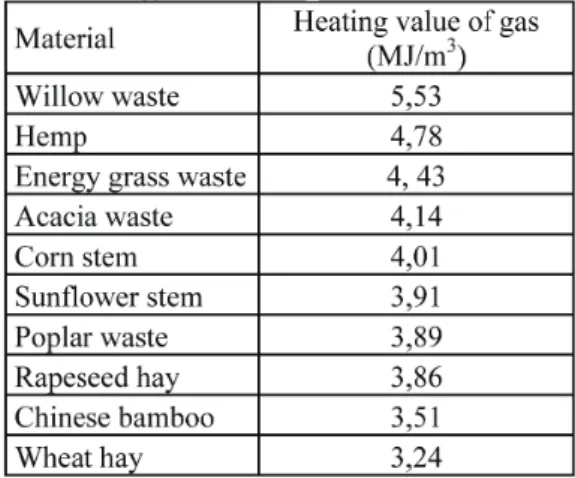
The various materials were carbonised in an inert (nitrogen) context, to obtain information on the estimated gas yield. The heating efficiency of these gases was also determined, and our resulting values are summarised in Table 1.
Table 1. Energy content of gases from carbonisation
The base moisture content for all materials was between 14- 15%, and their heating efficiency for dry material was between
11-19 MJ/kg. The highest heating efficiency was produced by poplar waste.
During carbonisation in inert gases, mass changes were also measured among different temperatures using a precision scale.
We introduce such changes on Figure 2.
Usually, lower temperatures yielded more remaining materials (carbon, and other materials that cannot be subject to pyrolisis).
Therefore, by increasing the temperature of pyrolisis, remaining materials lessen, meaning the samples "burn out" more [17].
On low temperature, the highest amount of remaining material resulted for soil-contaminated wooden waste, which may be due to how this sample also had much more, harder to combust materials as well, which can't be combusted on 400oC. A similar case happened for cut roots, which had significant amounts of soil.
Between hay, agri- and corn stem pellets, there was no significant difference of carbonisation speed on 400 and 600oC.
However, in cases of lower temperatures, there was always a higher difference. If latter materials are compared to pine waste and pellet made out of it, we will always result in faster carbonisation.
For hay and cane variants, there was difference in intensity of carbonisation, but the decomposition of remaining materials is also faster on lower temperatures.
This phenomenon may be due to the ligno-cellulose content (according to literature sources as well), and the temperature interval of their decomposition, which is intensive between
400 – 500°C.
After multiple analyses conducted with materials not listed here, and trials of ash decomposition, we conducted the designing phase of the machinery.
Figure 2. Mass change intensity of materials in inert gas between 400 and 1000°C
4. The planned system
(GG-100 wooden gas generator example's characteristics) The system is a so-called multiphase fixed bed solution, which separates the thermo-chemical transformation process into multiple parts using separate reaction zones into partial processes (drying, pyrolisis, oxidation, reduction). This makes the whole process easier to regulate (Figure 3). Therefore, the system can produce quality generator gas.
The freed energy is used to sustain the endothermal reduction process of the pyrolisis that happens with coke, thus reducing said coke (or coal) into generator gas, via the partial oxidation's resulting gaseous by-products.
Most of the energy of the high heat-content gas exiting the gas generator can be reclaimed by drying the fuel. The oxidation airflow is fed into the reactor after pre-heating it to 250ºC in the heat exchanger next to the input area, which also increases the efficiency of the system.
The system consists of five main parts I. Fuel system
– fuel (biomass waste) container, – fuel dredging system,
– fuel drier,
– collector, elevator system.
II. Gas generator – fuel input floodgates, – combustion airflow system, – hot air ignition grate, – ash disperser.
III. Gas preparation area – gas cooling,
– gas filtering, – gas purifying, – pressurisation.
IV. Gas engine and electricity generator – engine,
– electric generator, – hydraulics system,
– heat usage system (smoke gas– and engine - water. oil – heat exchangers)
V. Electronic operation system
– material input, temperature control of gas generator, gas quality (purifiers), gas temperature and pressure control
– gas generator, gas engine and electric generator controls – management of aforementioned systems, cooperation with the
electric grid.
– The entire control system is placed in the control technology container (with the visualisation of data, and the option of local intervention).
Structure of the system
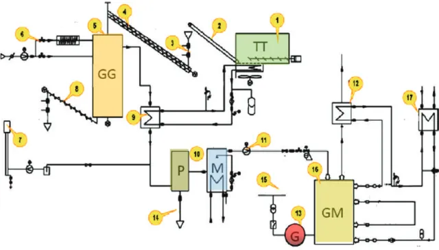
Figure 3. Schematics of the system, name of components
(1) fuel container and drier machine, expulsion machine (TT), (2) transport lane,
(3) feeder (floodgates), (4) fuel pulley, (5) wood gasification generator (GG), (6) airflow, electric ignition, (7) gas torch, (8) ash separator, ash disperser, (9) heat exchanger, (10) gas purification filter, gas purifier (P and M),
(11) pressuriser, (12) gas engine's expulsor heat exchanger (gas / water, heating and / or HMV), (13) electric generator (G), (14) ash separated in the purifier, (15) electric grid connection,
(16) gas engine (GM), (17) engine heat waste heat exchanger (heating and / or HMV)
The reactor-side part of the system's example can be seen on Figure 4.
Figure 4. Fuel (1), input floodgates (2), pulley (3), input into reactor space (4), dual-layer reactor (5), floating input (6), gas / air heat exchanger (7), dry dust filter (8), gas feed into gas engine (9),
gas torch (10).
Figure 5. Turbo load gas engine (1), turbo injector (2) electric generator (3), pressure valve (4)
heat exchangers of engine waste (5)
The generator gas has to be filtered to 0,5 micron
softness before it goes into the gas engine. The
maximum permissible dust content is 50 mg/Nm
3. The generator gas is 90-150°C when going from the heat exchanger to the gas filter, where it collides into a Nomex filtering bag with the dimensions of 1000 and 1200 mm. Following this, we also need to remove the volatile components, and those that dilute in water as well, which happens in a water purifier. The purified gas is fed to the turbo load gas engine via a pressuriser.
(Made by LIEBHERR) This is integrated into the electric generator (Figure 5).
The GAS ENGINE is four-cycle, six-cylinder, watercooled, sequential. The turbo loader operating with exhaust gas inputs the mixture under pressure.
System operation, communication
Within the operation and communication system, there are two sub-PLC systems and a main PLC system (made by UNITRONICS), connected to each other on a CAN bus, using a UNICAN protocol. The master PLC system has RS232, RS485, CAN and ETHERNET communication protocols installed.
Local and internet overseeing connects to the control centre via the ETHERNET port, but its operations are unrelated to that of communications necessary for the system.
The roles of the three-sided PLC group:
PLC1 tasks:
–visual representation of the system (Figure 6), –regulation, controlling,
–generating and managing technical and electric protection protocols,
–error management, logging,
–communication with PLC2 and PLC3, –local and web overseeing,
–network connection with EID-EP.
PLC2 tasks:
–normal operation of gas engine, –rev and performance regulation, –performance factor regulation, –watercooling system regulation, –mixture regulation,
–technical and electric protection protocols of gas engine,
–gas fuel system regulation.
PLC3 management and overseeing tasks:
–pre-drier,
–fuel input floodgates,
–temperature processes in gas generator, –gas constitution,
–airflow intake,
–movement of floodgates, –ash dispersion,
–units of dry filter and wet purifier, etc.
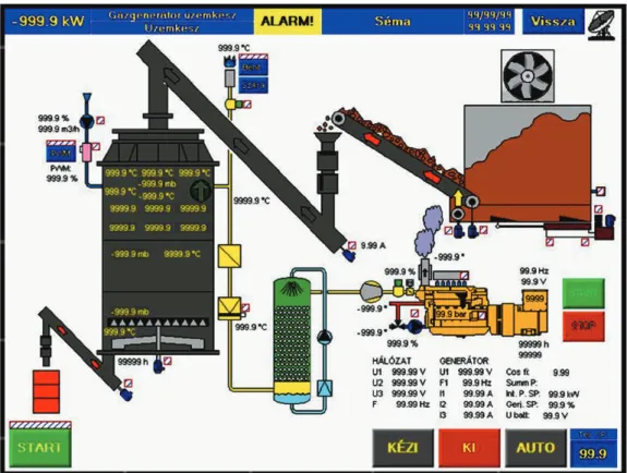
Figure 6. Information manual management interface shown in PLC1 (fuel system, gas generator, gas engine operation parameters and necessary management appliances included)
5. System analysis, results
We measured the energetic parameters of the system after the complete "heating". We precisely described the grain constitution of the input material (in accordance with relevant standards), similarly to its moisture content, heating coefficient, the
temperature values within the gas generator, the gas temperature, gas composition, etc.
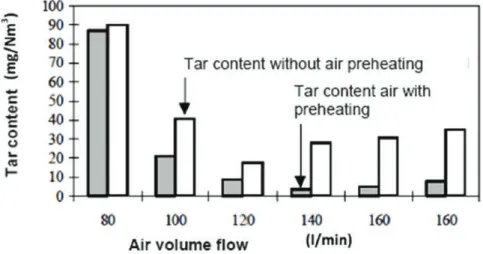
Due to the pre-heated air in the system, the oxidation zone has a higher temperature, and cracking the long carbon chain of tar also happens (Figure 7).
Figure 7. Tar content in light of preheated airflow effects
Table 2. Temperatures of the experimental
Table 3. Performance measurements of the experimental device
The fuel consumption of the system is 13 MJ/kg heat performance, 25% moisture content biomass waste, with at most 1,5% ash content. The fuel requirement for an hour if moisture content of the waste is 25% (for dry material) is 108 kg.
Figure 8. Percentage of performance values for experimental device
In our experimental device, we used 1kg of biomass to produce 2,5 m3wood gas, which had an average of 5,35 MJ/m3heating efficiency (when the heat efficiency of the dry wood used for the experiments was 18 MJ/kg).Cold efficiency of the gas generator:
Where:
– Hagas: Heating coefficient of generator gas [kJ/mn3]
– qgas: Volume flow of generator gas [mn3/h]
– Hah: Heating coefficient of average fuel [kJ/kg]
– qfm: Fuel mass flow [kg/h]
Finally, by using the pyrolisis generator, we were able to make an efficient CHP power plant system, where in the case of 18- 19% moisture content hardwood waste (12-45cm):
– Total efficiency for electricity is: 28,4-28,9% (~29%).
– CHP efficiency is: ~75%, σ = 0,63 after "lab measurements".
6. Operation conditions
The system links into a mid-voltage grid, and cooperates with it, but the transportation of electricity at the point of intersection is one-way, it can only draw.
The machinery is placed in a facility processing woodwork waste, where top electricity consumption is around 124 kW. The main machines responsible for consumption are the shredder, pellet maker and bricket maker machines that describe the facility's profile.
On the electric intersection point, there's an EID-EP unit from the EuroProt+ Smart series, made by PROTECTA Co. Ltd. This offers a solution for protecting free cable and cable systems on the grid, for both civilian and industrial use. This means that (in its current place) the facility draws 24 kW performance from the grid for TDP, however, when the demand is lower, the operation of the power plant cooperating with the EID-EP stops the drawing, and feeds demand back to the gas generator. The highest rate of this process - without significantly debilitating efficiency - is ~50%. Demand below this only happens during 20% of the facility's time in operation. Currently, the machinery don't operate on Saturdays and Sundays.
We wish to make the machinery operate around the clock. This requires that we construct a two-part fuel container unit that's larger in size. One part contains the dry fuel, another the wet fuel.
On weekends, the gas generator of the machinery can keep operating, if the gas produced is combusted, and its heat energy is used in the larger thermo-ventilator installed at the pre-drier (meaning it's used for pre-drying its own fuel).
Conclusions
According to our goals, we were able to create a pyrolisis power plant of CHP 100kWpe , which can be used to process woodwork waste and agricultural solid biomass (f. e. by-products) for energetics purposes. The solution is exceptionally good for sustaining rural SMEs as an energy supply. They can employ part- timers for the system's heat production, but it can also be used well as an energy supply unit for small factories needing electricity and heat energy. Using this machinery, materials produced in the direct neighbourhood of rural areas can be used.
The collection and processing of said materials can also mean more workplaces. We can exploit areas only usable for producing energy plants, the environment becomes more refined, and the gains also serve the locals, increasing the capability of rural areas to keep inhabitants.
References
[1] Birkás M.: 2015. Környezetkímélő alkalmazkodó talajmű - velés. Szent István Egyetemi Kiadó, Gödöllő, pp. 368.
[2] D’Antonio C. M.:1993 Mechanisms controlling invasion of costal plant communities by the alien succulent Carpobrotus
edulis. Ecology, Vol. 74. No. 1. pp. 83–95.
http://dx.doi.org/10.2307/1939503
[3] Dassonville N., Vanderhoeven S., Vanparys V., Hayez M., Gruber W., Meerts P.: 2008. Impacts of alien invasive plants on soil nutrients are correlated with initial site conditions in NW Europe. Oecologia, Vol. 157. pp. 131–140.
http://dx.doi.org/10.1007/s00442-008-1054-6
[4] Ehrenfeld J. G.: 2003. Effects of exotic plant invasions on soil nutrient cycling processes. Ecosystems, Vol. 6. pp. 503–523.
http://dx.doi.org/10.1007/s10021-002-0151-3
[5] Evans H. C.: 1997. Parthenium hysterophorus, a review of its weed status and the possibilities for biological control.
Biocontrol News and Information, Vol. 18. No. 3. pp. 89–98.
[6] Tóth L.: 2012 Alternatív energiaellátási rendszerek az agrárgazdaságban, Szaktudás Kiadó, Budapest, pp. 320.
[7] Lettner, F., Haselbacher, P., Timmerer, H., Leitner P.:
2007. Latest results of "CleanStGas" - Staged biomass gasification CHP, Proceedings of the 15th European Biomass Conference & Exhibition, Berlin
[8] Madár V., Tóth L.: 2012. Fagázgenerátor üzemű bio- kiserőmű és öntözőberendezés, Mezőgazdasági Technika, Vol.
52. No. 9. pp. 3-8.
[9] Di Blasi C.: 2009. Combustion and gasification rates of lignocellulosic chars. Progress in Energy and Combustion Science, Vol. 35. No. 2. pp. 121–140.
http://dx.doi.org/10.1016/j.pecs.2008.08.001
[10] Raman P., Ram N.K., Gupta R.: 2013. A dual fired downdraft gasifier system to produce cleaner gas for power generation, Design, development and performance analysis.
Energy Vol. 54. pp. 302-314.
http://dx.doi.org/10.1016/j.energy.2013.03.019
[11] Bhattacharya S.C., Siddique A.H.M.R., Pham H.L.:1999.
A study on wood gasification for low-tar gas production. Enegy Vol. 24. No. 4. pp. 285-296. http://dx.doi.org/10.1016/S0360- 5442(98)00091-7
[12] Madár V., Tóth L., Madár Gy., Schrempf N.: 2014.
Kísérleti fagázgenerátor Mezőgazdasági Technika, Vol. 55. No.
4. pp. 2-5.
[13] Barman N.S., Ghosh S., Sudipta D.: 2012. Gasification of biomass in a fixed bed downdraft gasifier – A realistic model including tar. Bioresource Technology, Vol. 107. pp. 505-511.
http://dx.doi.org/10.1016/j.biortech.2011.12.124
[14] Antonopoulos I.S., Karagiannidis A., Elfsionitis L., Perkoulidis G., Gkouletsos A.: 2011. Development of an innovative 3-stage steady-bed gasifier for municipal solid waste and biomass. Fuel Processing Technology, Vol. 92. No. 12. pp.
2389-2396. http://dx.doi.org/10.1016/j.fuproc.2011.08.016 [15] Dhaundiyal A., Gupta V. K.: 2014. The analysis of pine needles as a substrate for gasification. J. Water, Energy Environ.
Vol. 15. pp. 73–81. http://dx.doi.org/10.3126/hn.v15i0.11299 [16] Martínez J. D., Lora E. E. S., Andrade R. V., Jaén R. L.:
2011. Experimental study on biomass gasification in a double air stage downdraft reactor. Biomass and Bioenergy, Vol. 35. No. 8.
pp. 3465-3480. http://dx.doi.org/10.1016/j.biombioe.2011.04.049 [17] Borocz M., Herczeg B., Horvath B., Fogarassy Cs.:
Evaluation of biochar lifecycle processes and related lifecycle assessments. Hungarian Agricultural Engineering, Vol. 29. pp.
60-64. http://dx.doi.org/10.17676/HAE.2016.29.60