CHAPTER ^
Preparation of Samples for Analysis
It is assumed that a sample submitted for microanalysis is pure. I f it is a liquid, it should have been subjected to fractionation and be a constant boiling fraction. I f it is a solid, it should have been crystallized, preferably from more than one type of solvent, until additional crystallization did not raise the melting point. The purification of a sample really has no place in a book on microanalysis. Therefore, very little about the methods should be given here.
However, during the existence of every large microchemical laboratory, a few purification problems are encountered. The research chemist with but a few milligrams of precious material often consults the microchemist for suggestions for purification. Such emergencies are handled almost always by merely adapt
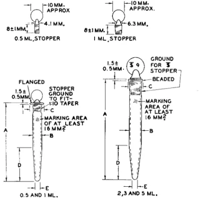
ing macromethods to the microsize samples using filter tubes (Chapter 1 1 ) , filter sticks and crucibles (Chapter 1 0 ) , centrifuge tubes, etc. For example, crystallization may be made in centrifuge tubes and the crystals collected by c e n t r i f u g i n g2 0-6 5'1 0 1'1 0 7'1 2 8 instead of by filtration. The microcentrifuge tubes1 1 8 shown in Figs. 58, 59, 60, and 61 are well adapted to micropurification work—
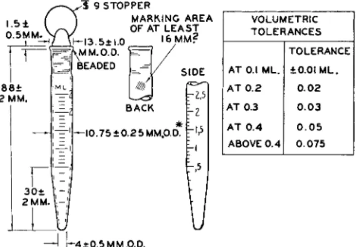
collecting precipitates and separation of liquid fractions. The tubes with the cylindrical bottoms will be found to be particularly useful when working with small quantities of precipitates. The graduated tube shown in Fig. 6 1 , as well as the microvolumetric flasks1 1 8 (Fig. 7 4 ) and p i p e t t e s1 1 8 , 1 1 9'1 2 0 (Figs. 75, 76, and 7 7 ) , all described in Chapter 5, also will be found to be useful.
Two methods of purification which have proved useful in the author's laboratory are presented below.
DRY CRYSTALLIZATION115116
One method of crystallization, while little known, is extremely useful for handling a few milligrams of material. It is the H o o k e r1 1 5'1 1 6 method of dry crystallization which is as follows: The material is placed in a small Erlenmeyer flask (about 2 5 - 5 0 ml. capacity), one or two drops of solvent are added, and solution is effected by heating the contents with a microburner* while the flask is held in an almost horizontal position. The flask is then placed, in this posi
tion, on a suberite ring and the contents allowed to cool and evaporate (Fig.
* See Fig. 181, Chapter 16.
83
6 2 ) . As evaporation occurs, the resulting rim of crystals is washed down, from time to time, into the mother liquor. When the contents go to dryness, the purified crystals are found in the center of a circle of resinous material. The crystals are loosened and the flask turned so as to move the crystals to a clean
BEADED
I.510.5MM.
FLANGED
V
D111
-MARKING AREA OF AT LEAST 16 MM?
h-B
Τ
IKMARKING AREA OF AT LEAST
16 MM?
!h-B
0.5 AND I ML. 2 , 3 AND 5 ML.
FIG. 58 . Microcentrifuge tube with conical bottom, plain— -details of construction.
Ρ Nominal
capacity (ml.)
A Over-all
height (mm.)
Β Outside diameter cylindrical
portion (mm.)
C Outside diameter top finish
(mm.)
D Length of taper
(mm.)
Ε Outside diameter at bottom
(mm.) 0.5
1 2 3 5
58 ± 2 61 ± 2 66 ± 2 74 ± 2 101 ± 2
6.0 ± 0.25 8.25 ± 0.25 10.75 ± 0.25*
10.75 ± 0.25*
13.0 ± 0.50
13 ± 1.0 13 ± 1.0 13.5 ± 1.0 13.5 ± 1.0 16.25 ± 0.75
30 ± 2 30 ± 2 30 ± 2 30 ± 2 40 ± 2
3.5 ± 0.5 3.5 ± 0.5 4.0 ± 0.5 4.0 ± 0.5 4.0 ± 0.5 Wall thickness of all sizes to be approximately 1 mm.
* The outside diameter of 2 and 3 ml. must not exceed 11.0 mm.; otherwise tubes will not fit into centrifuge shields.
Bottoms to be rounded.
place in the flask. The resinous rim is removed by a cotton swab moistened with a solvent and the crystals are again dissolved and the process repeated a number of times.
SUBLIMATION
The microsublimator of the t y p e5 2-6 3 , 1 1 5 shown in Fig. 63 is useful for purify
ing samples which sublime either at atmospheric pressure or in vacuo. The crude material is placed in the lower container which is heated and can be
85 Preparation of Samples for Analysis
evacuated. T h e sublimate collects on the upper water-cooled jacket and can be removed on dismantling.
— F Κ1 0 MM.
APPROX -4.1 MM.
8 + I M M . Q
0.5 ML STOPPER
—Η H-10 MM.
L-J APPROX.
~ p- 6 . 3 M M . θ ± Ι Μ Μ . ] ~ | ^
I ML STOPPER
X GROUND
o
liL
roR*
FLANGED
^MARKING AREA OF AT L E A S T I 6 M M ? K B
— I U E
0 . 5 AND I ML.
2 , 3 AND 5 ML.
FIG. 59. Microcentrifuge tube with conical bottom, stoppered—details of construction.
Outside C Ε
A diameter Outside D Outside
Nominal Over-all cylindrical diameter Length diameter
capacity height portion top finish of taper at bottom
(ml.) (mm.) (mm.) (mm.) (mm.) (mm.)
0.5
66 ±2
6.0 ± 0.25 13 ± 1.0 30 ± 2 3.5 ± 0.51 69 ± 2 8.25 ± 0.25 13 ± 1.0 30 ± 2 3.5 ± 0.5
2 80
± 2
10.75 ± 0.25* 13.5 ± 1.0 30 ± 2 4.0 ± 0.5 388 ±2
10.75 ± 0.25* 13.5 ± 1.0 30± 2
4.0 ± 0.55 115 ± 2 13.0 ± 0.50 16.25 ± 0.75 40 ± 2 4.0 ± 0.5
Wall thickness of all sizes to be approximately 1 mm.
* The outside diameter of 2 and 3 ml. must not exceed 11.0 mm.; otherwise tubes will not fit in centrifuge shields.
Bottoms to be rounded.
13 S t l . O M M . I 3 . 5 ± I . 0 M M .
Γ 1 I.5 + 0 . 5 M M .
6 6 ±
2 MM
Η
BEADED- \ — 1 0 . 7 5 ± 0 . 2 5 *
1 \ MM.O.D
ι MARKING AREA 0 F „
x / A T L E A S T 16 M M ? 3 3 i
u
I M M .
I M P O R T A N T : NO C 0 N - ,ntfH, S T R I C T I O N A T MM.LO. TH,S P0,NT
f -— ~ | J L 5 ± 0 . 5 M M .
BEADED I 0 . 7 5 ± 0 . 2 5 *
M M.O.D.
MARKING AREA O F j A T L E A S T 16 M M . 2 / • - - I M P O R T A N T : N O C O N
S T R I C T I O N AT T H I S 2 . 0 1 0 . 1 3 P0,NT
MM.I.D.
CAPACITY APPROX. 1.8 M L . CAPACITY APPROX. 2 . 6 M L .
FIG. 60. Microcentrifuge tube with cylindrical bottom, plain.
Wall thickness of both sizes to be approximately 1 mm.
* The outside diameter of both sizes must not exceed 11.0 mm.; otherwise tubes will not fit into centrifuge shields.
Bottoms to be rounded.
I . 5 ± 0.5MM.
8 8 ±
2 MM.
Γ
3 0 ±
2 MM.
1 9 STOPPER
MARKING AREA OF AT LEAST I 3 . 5± l. 0 I6MM?
^MM.OTD. * BEADED
BACK H - I0.75±0.25MM.O.D.
F-.5
VOLUMETRIC TOLERANCES
TOLERANCE AT 0.1 ML. ±0.01 ML.
AT 0 . 2 0.02 AT 0.3 0 . 0 3 AT 0. 4 0 . 0 5 ABOVE 0. 4 0 . 0 7 5
-J U4±0.5MM,O.D.
FIG. 6 1 . Microcentrifuge tube with conical bottom, stoppered, graduated, 2.5 ml. in 0.1 ml.—details of construction.
Wall thickness to be approximately 1 mm.
* Outside diameter must not exceed 11.0 mm.; otherwise, tube will not fit into centrifuge shields.
Bottom to be rounded.
CRYSTALS
FIG. 6 2 . Hooker dry crystallization.
87 Homogeneity of Samples
>
] FIG. 63. Microsublimator.
Homogeneity of Samples
Obviously, a pure sample is homogeneous as to composition. However, the question of purity often arises when the analyst fails to obtain values in agree
ment with the theoretical ones for the compound believed to have been sub
mitted for analysis. Since the "analyst is always wrong" in the opinion of the chemist submitting the sample, the analyst must be able to defend his results.
The analyzing of test substances is the analysts' means of defense. However, the question often arises as to why several analyses on the submitted sample do not check each other. Obviously if the sample is not homogeneous, each analysis will differ unless the components have the same percentage compositions. The lack of homogeneity of solid samples can be demonstrated often with the aid of a microscope, particularly if a Kofler micro hot stage is used for the de
termination of the melting point as explained in connection with the opera
tion of this instrument (see Chapter 2 2 ) . The nonhomogeneity of liquid samples cannot be as easily demonstrated, unless, of course, portions change color or precipitates are present. Although a liquid shows no change, each time the sample bottle is opened lower-boiling components evaporate at a faster rate than the high boiling ones, surface oxidation or absorption of carbon dioxide may occur, etc. Remembering the above can be helpful to the analyst on such occasions.
Apparatus
SAMPLE CONTAINERS
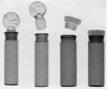
Figure 64 shows the types of amber glass vials* in which samples for analysis are submitted to the author's laboratories. The ground glass stoppered vial is used for liquids. It is approximately 45 mm. in length and 13 mm. in outside diameter, and is fitted with a solid Τ 8 stopper. The polyethylene stoppered vial
FIG. 6 4 . Sample containers: ground glass stoppered type for liquids; plastic cap type for solids.
is used for solids. It is approximately 45 mm. in length and 14.5 mm. in out
side diameter. Both types have been in use for the past twelve years and have proved to be quite satisfactory.
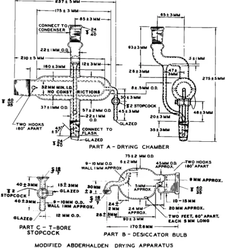
MODIFIED ABDERHALDEN DRYING APPARATUS5
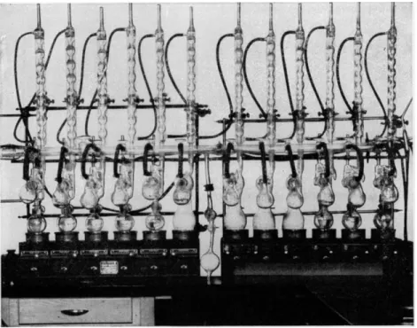
The drying apparatus shown in Fig. 65 is a modification of the original Abderhalden pistol drier,26.27.44;49(50,80-82)88,89)i02-i05,ii5,i2i a battery of which is shown in Fig. 66. The original model obtained the name of "pistol drier"
because of its shape. It permitted drying only in vacuo, while the modified apparatus shown in Fig. 65 permits the drying of samples by the passage of dry air at reduced pressure, in accordance with the newer methods of drying,1 2 1' 126,127, a s w e
] j [
a s eliminates structural disadvantages of the early models.* Available from Kimble Glass Company, Subsidiary of Owens-Illinois Glass Com
pany, Vineland, New Jersey.
89 Apparatus
The drying apparatus consists of the following parts whose functions are described :
Boiling Flask
Into this is placed whatever liquid (acetone, alcohol, water, acetic acid, toluene, xylene, /^-cymene, etc.) is required for the vapors, produced by boiling, to give the desired drying temperature.
Drying Chamber (Part A, Fig. 65)
This is composed of the sample compartment, which connects on the left to the desiccator bulb (Part B , Fig. 6 5 ) , and the vapor compartment, which acts as a hot envelope for the sample compartment. The lower joint connects to
- ^ G L A Z E D
P A R T A - D R Y I N G C H A M B E R
7 5 ± 2 M M O.D 9 - 1 0 M M
W A L L I M M A P P R O X
3±3MM
S T O P C O C K
4 0 ± 3 M M
G L A Z E D
t ' " " " 30MM
G L A Z E D ± S J _ _
5
1 · /_ _ . 7 W A L L I MM A P P R O X .
12 MM O . D .
• MM A P P R O X .
P A R T C - T - B O R E S T O P C O C K
T W O F E E T . 60* A P A R T . E A C H 5 MM L O N G
P A R T Β - D E S I C C A T O R B U L B M O D I F I E D A B D E R H A L D E N D R Y I N G A P P A R A T U S
FIG. 6 5 . Modified Abderhalden drying apparatus—details of construction.
the boiling flask and the upper joint connects to the reflux condenser. The reflux returns into the flask, but the upward indentation in the vapor tube (end view) prevents cooling of the drying chamber by cold condensate. At the right end of the chamber is a stopcock through which dried air (passed over a desiccant) at reduced pressure may be passed over the sample, if desired.
Otherwise, this stopcock is kept closed for conventional vacuum drying.
Desiccator Bulb (Part B, Fig. 65)
Into this is placed the desiccant, such as phosphorus pentoxide. The desiccator bulb connects to the drying chamber. The bulb is so designed that it may be detached and rested on the table without additional support. The shape of the tube attached to the ball joint is intended to prevent the desiccant from being carried into the sample when the vacuum is broken. The T-bore (three-way) stopcock (Part C, Fig. 6 5 ) connects the system to the source of vacuum and allows the vacuum to be broken at the source without breaking it in the flask or vice versa. A cap for the ball joint and a stopper for the ΊΓ 4 0 / 5 0 joint may be used to protect the desiccant when the desiccator bulb is temporarily dis
connected from the drying chamber and stands alone.
During the drying process, the vapor from the boiling flask passes up
FIG. 66. Battery of Abderhalden drying apparatus.
91 Determination of Moisture
through the drying chamber and then into the water-cooled condenser where it condenses and returns to the boiling flask. A number of these should be set up, with a variety of solvents, having different boiling points, so that a number of drying temperatures are always available. Acetone, alcohol, water, acetic acid, toluene, xylene, /^-cymene, etc., are recommended for providing drying ranges from about 55 to 175° C. and over. Although phosphorus pentoxide is generally used as the desiccant, others1 , 7 may be used. For the removal of certain nonpolar solvents, such as benzene, from samples, paraffin chips have been used. Figure 66 is a photograph of the setup in the author's laboratory. It consists of a battery of twleve electrically heated driers, con
nected to a manifold, which in turn is connected to vacuum pumps (backing and diffusion) and gauges. With this battery, it is possible to dry at the above- mentioned range of temperatures and at pressures as low as 1 χ 10 ~5 mm.
of Hg. The use of three-way stopcocks on the manifold allows the vacuum to be broken on one flask with no disturbance to the others or to the rest of the vacuum system.
VACUUM OVENS
Small electrically heated vacuum ovens can also be used for drying samples.
The temperature is thermostatically controlled to that desired.
ORDINARY LABORATORY OVENS
Ordinary laboratory drying ovens usually found in chemical laboratories may be used for drying filter tubes, crucibles, etc., but usually not samples.
Determination of Moisture
To be perfectly safe, all solid compounds should be dried to constant weight before being analyzed. However, in a large laboratory handling thousands of samples, this becomes almost an impossibility and actual moisture determina
tions are done on but a comparative few.
Ordinarily, samples are merely dried for several hours in vacuo (0.1-0.5 mm. of H g * ) over phosphorus pentoxide (or some other desiccant),1-7 at some temperature well below their melting points previous to their being analyzed.
(With some materials, more efficient drying is accomplished by allowing dry air to be sucked, at reduced pressure, through the partly open stopcock on the drying chamber. The passage of the dry air over the sample aids the removal of the water v a p o r .1 2 1'1 2 6-1 2 7) This will suffice to remove moisture and solvents in the majority of cases. The exact time of drying and the temperature re-
* High vacuums are rarely needed and increase the possibility of loss by sublimation.
cjuired to do the job is anybody's guess. The safest rule to follow is to dry for a number of hours in a good vacuum and at a relatively low temperature, since the lower the temperature the less possibility of decomposition. In spite of the fact that a sample melts rather high (as, for example, 225° C ) , when heated rapidly in a melting point determination, heating at 8 0 ° C. for many hours might cause decomposition, yielding a tar. Fortunately, such cases are the exception, but the possibility must be considered when dealing with valuable materials.
The following method is used for drying to constant weight or for deter
mining the moisture present. I f available, 5 0 - 7 5 mg. of material are weighed in a pig (Fig. 2 9 ) (taking into account the zero reading) and dried at some temperature well below its melting point in vacuo over phosphorus pentoxide.
After several hours, the sample should be cooled and weighed. (The sample should be observed for signs of decomposition and the cold portion of the drying chamber should be examined for sublimate. In either case, the deter
mination is valueless and an attempt should be made to dry at a lower tempera
ture.) It should then be returned to the drier and again heated for several hours and then reweighed. The process should be repeated until no further loss is noted. (Some samples decompose at such a slow rate that a loss of 0 . 1 % will be noted after each successive drying of 6 - 8 hours which will go on for days unless the experiment is stopped.)
Calculation:
Loss in wt.
— - — - , τ - χ 100 = % loss* on drying
W t . of sample 7 1 °
SPECIAL CASES
When the water or solvents are merely absorbed by the material the matter of driving them off is much easier than if they are bound up as water or solvent of crystallization.1 1 5'1 1 7'1 2 5 In these latter cases the substance often decom
poses in the process of becoming anhydrous and the sample must be analyzed with the substance of crystallization attached. The idea of an organic compound crystallizing with water or solvent of crystallization such as ethanol, methanol, acetic acid, acetone, or benzene is a hard one for the organic chemist to "swal
low" particularly when these are present in such amounts as l/2, 1, l i /2, or 2 molecules in the compound. In the author's laboratory, many such cases have been encountered.1 1 5'1 1 7 I f the sample contains water of crystallization, and will not yield it on heating, proof will have to rest on the elementary analyses unless a Karl Fischer determination4 0'6 9'8 4-1 1 1 is successful. If, however, ethanol,
* Loss may be due to water or solvents, either mechanically held or as water or solvent of crystallization.
93 Additional Information for Chapter 4
methanol, acetic acid or acetone of crystallization is present, a determination of ethoxyl, methoxyl, acetyl, or acetone, respectively, will furnish proof of the e x i s t e n c e .1 1 5'1 3 7 Determination of ethoxyl and methoxyl are carried out as described in Chapter 16, the determination of acetyl as described in Chapter 17, while acetone of crystallization may be determined by the colorimetric method of Czonka.3 2 The determination of oxygen, as described in Chapter 14, often furnishes conclusive data.
Combinations of solvents are also sometimes found attached to organic molecules. Twenty years ago in the author's laboratory a substance was found to have water, methanol, and acetone of crystallization.1 1 5-1 1 7 Fortunately, it yielded the solvents, on heating, which were collected and analyzed qualitatively as follows. The presence of methanol was proved by (a) conversion to formal
dehyde,4 ( b ) Vorisek test,4 and ( c ) conversion to ^-nitromethyl benzoate which was identified by melting point ( 7 8 ° C.) and mixed melting point with a known sample.5 6-6 1 The presence of acetone was proved by (a) iodoform reaction,6 1 ( b ) sodium nitroprusside test,5 7-7 9 and ( c ) conversion to the p-nitro- phenyl hydrazone which was identified by melting point ( 1 4 8 ° - 1 4 9 ° C.) and mixed melting point with a known sample.5 7-6 1 Neither methanol nor acetone could have resulted from decomposition of the compound. Analyses were then done on the solid material. The methanol was obtained quantitatively by a methoxyl determination and the acetone quantitatively by the method of Czonka referred to above.
If a sample containing alcohol of crystallization is placed over water in a closed system, such as under a bell jar or in a desiccator, there often occurs a replacement of the alcohol in the molecule by w a t e r .1 1 5-1 2 5 In many such cases, the water of crystallization is then more easily removed than is the alcohol.
Besides the presence of solvents of crystallization, the analyst might encounter other special cases which alter the analyses. Amine hydrochlorides and phosphates have been analyzed which contained an additional molecule of hydrochloric and phosphoric acids, respectively, than was required for the formula (3 mol HC1 although only 2 nitrogens were present and 2 mol H3P 04 although only 1 nitrogen was present, respectively). The analyses of carbon, hydrogen, nitrogen, and halogen or phosphorus substantiated these theories.1 1 7
ADDITIONAL INFORMATION FOR CHAPTER 4
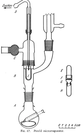
When it is necessary to concentrate small amounts of solutions by evapora
tion of the solvent in a dust-free atmosphere and with the prevention of creep
ing, the apparatus9 3 shown in Fig. 67 will prove helpful. It consists of a boiling flask, A, into which is placed whatever liquid is necessary to produce the desired evaporation temperature. Heating is accomplished by means of
an electric immersion heater. On the way to the reflex condenser, the vapors surround the evaporation vessel, E, which is secured in a heating well in the body, B. The suction tube, D, fits into a rubber sleeve and can be raised or lowered. Air enters the drying chamber through the cotton filters at C. The
FIG. 67. Perold microevaporator.
tip of the suction tube, D, is kept just above the surface of the liquid in Ε at all times. Air is drawn down along the inner wall of E, which prevents creeping.
The determination of water has been done by means of the Karl Fischer r e a g e n t .4 0'6 9'8 4-1 1 1 This method involves the direct titration of the wet material
95 Additional Information for Chapter 4
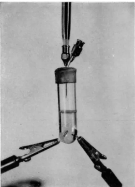
with a solution of iodine, sulfur dioxide, and pyridine in methanol. Levy, Murtaugh, and Rosenblatt6 9 adapted the method to the microscale (Fig. 6 8 ) . They used a small titration vessel made from a 16-mm. diameter test tube into which are sealed platinum electrodes. These electrodes are connected with an
FIG. 68. Levy-Murtaugh-Rosenblatt vessel.
electrometric apparatus by means of clamps. The vessel is closed with a tightly fitting serum bottle sleeved rubber stopper. Through the stopper are placed two hypodermic needles, one attached to a microburette for titration and the other open to the air and acting as a valve to equalize the pressure dur
ing titration.
For additional material in regard to apparatus, procedures, etc., related to the subject of this chapter, the reader is referred to Table 14, page 96.
T A B L E 14
ADDITIONAL INFORMATION ON R E F E R E N C E S * RELATED TO C H A P T E R 4
Following the plan used with the previous chapters, this table lists additional references the author wishes to call to the attention of the reader. (See statement regard
ing such information at top of Table 4 of Chapter 1.) Books
Belcher and Godbert, 10, 11 Benedetti-Pichler and Spikes, 13 Bernhauer, 15
Cheronis and Entrikin, 23, 24 Clark, E. P., 26
Clark, S. J . , 27
Emich and Schneider, 36 Furman, 44
Grant, 49, 50
Huntress and Mulliken, 57 Kamm, 61
Lieb and Schôniger, 70, 71 Milton and Waters, 8 1 , 82 Niederl and Niederl, 88, 89 Niederl and Sozzi, 90 Pregl, 96
Roth, 102-105 Schneider, 107 Steyermark, 115
Beakers, pipettes, centrifuge accessories
British Standards Institution, 18 Lieb and Schôniger, 70, 71 Distillation
Alber, 3 Babcock, 6
Belcher and Godbert, 10, 11 Bering, 14
Bernhauer, 15
Cheronis and Entrikin, 23, 24 Conolly and Oldham, 29 Dubbs, 33
Dubowski and Shupe, 34 Erdos, 37
Gould, 48 Grant, 49, 50 Haendler, 51 Hallett, 52 Irlin and Bruns, 58
Distillation (Conf.) Lappin, 67
Lesesne and Lochte, 68 Lieb and Schôniger, 70, 71 Morton and Mahoney, 85 Oldham, 91
Podbielniak, 95 Rose and Rose, 99 Schneider, 107 Shrader and Ritzer, 108 Crystallization
Benedetti-Pichler and Spikes, 13 Blount, 17
Cannon, 21
Cheronis and Entrikin, 23, 24 Craig, 31
Emich and Schneider, 36 Hallett, 52
Lieb and Schôniger, 70, 71 Schneider, 107
Shead, 109 Sublimation
Clarke and Hermance, 28 Erdos, 37
Fischer, 41
Flaschentrâger, Abdel-Wahhab, and Habib-Labib, 43
Grant, 49, 50 Hallett, 52
Hickman and Sanford, 54 Hippenmeyer, 55 Klein and Werner, 63 Lieb and Schôniger, 70, 71 Marberg, 75
McDonald, 77 Meyer, 78
Morton, Mahoney, and Richardson, 86 Soltys, 113
Werner, 123
* The numbers which appear after each entry in this table refer to the literature citations in the reference list at the end of the chapter.
97 Table of References
T A B L E 14 (Continued) Filtration
British Standards Institution, 18 Dubbs, 33
Emanuel, 35
Feldman and Ellenburg, 38 Lieb and Schôniger, 70, 71 Evaporation
Kurtz, 66
Lieb and Schôniger, 70, 71 Extraction
Cheronis and Entrikin, 23, 24 Craig, 30
Dubbs, 33
Kirk and Danielson, 62 Lieb and Schôniger, 70, 71 Neustadt, 87
Fractionation, separation, purification Batt and Alber, 9
Bickford, 16
Cheronis and Entrikin, 23, 24 Ferguson, 39
Gettler, Umberger, and Goldbaum, 45 Lieb and Schôniger, 70, 71
Malissa, 74 Perold, 93 Rosenthaler, 100 Soltys, 114
Ovens, desiccators, drying devices Alber, 1, 2
Barraclough, 7
British Standards Institution, 18 Clark, 26
Furman, 44 Grant, 49, 50 Knight, 64
Maurmeyer and Ma, 76 Milner and Sherman, 80
Ovens, etc. (Conf.) Milton and Waters, 81, 82 Niederl and Sozzi, 90 Pavelka, 92 Pregl, 96 Roth, 102-105 Smith, 112
Ten Eyck Schenck and Ma, 122 Drying and moisture in general
Bunzell, 19
Central Scientific Company, 22 Heckly, 53
Sandell, 106 Willits, 125, 126
Determination of moisture by neutron scattering
Johnson, 60 Karl Fischer
Bastin, Siegel, and Bullock, 8 Ciusa and Moroni, 25 Fischer, Karl, 40 Johansson, 59
Levy, Murtaugh, and Rosenblatt, 69 Mitchell, 83
Mitchell and Smith, 84 Peters and Jungnickel, 94 Ricciuti and Willits, 97 Roberts and Levin, 98
Smith, Bryant, and Mitchell, 111 Wiberley, 124
Cinnamyl chloride, naphthyl phos
phorus oxychloride, succinyl chloride, calcium carbide, etc.
Belcher, Thompson and West, 12 Gorbach and Jurinka, 46, 47 Fischer, R., 42
Lindner, 72, 73 Sirotenko, 110
REFERENCES
1. Alber, H. K., Mikrochemie ver. Mikrochim. Acta, 25, 47 ( 1 9 3 8 ) . 2. Alber, H. K., Mikrochemie ver. Mikrochim. Acta, 25, 167 ( 1 9 3 8 ) . 3. Alber, Η. Κ., Z. anal. Chem., 90, 100 ( 1 9 3 2 ) .
4. "Allen's Commercial Organic Analysis" ( S . S. Sadder and E. C. Lathrop, eds.), 5th ed., Vol. I, p. 95, Blakiston, Philadelphia, Pennsylvania, 1923.
5. American Society for Testing Materials, AST M Designations, E 1 2 4 - 5 6 T ( 1 9 5 6 ) , E 1 2 4 - 5 7 T ( 1 9 5 7 ) .
6. Babcock, M. J . , Anal. Chem., 21, 632 ( 1 9 4 9 ) . 7. Barraclough, K. C , Metallurgia, 31, 269 ( 1 9 4 5 ) .
8. Bastin, E. L., Siegel, H., and Bullock, A. B . , Anal. Chem., 31, 467 ( 1 9 5 9 ) . 9. Batt, W . G., and Alber, H. K , Ind. Eng. Chem., Anal. Ed., 13, 127 ( 1 9 4 1 ) .
10. Belcher, R., and Godbert, A. L., "Semi-Micro Quantitative Organic Analysis,"
Longmans, Green, London, New York and Toronto, 1945.
11. Belcher, R., and Godbert, A. L., "Semi-Micro Quantitative Organic Analysis," 2nd ed., Longmans, Green, London, 1954.
12. Belcher, R., Thompson, J . H., and West, T. S., Anal. Chim. Acta, 19, 148 ( 1 9 5 8 ) . 13. Benedetti-Pichler, Α. Α., and Spikes, W . F., "Introduction to the Microtechnique of Inorganic Qualitative Analysis," Microchemical Service, Douglaston, New York, 1935.
14. Bering, P., Svensk. Kern. Tidskr., 61, 10 ( 1 9 4 9 ) .
15. Bernhauer, K., "Einfiihrung in die organisch-chemische Laboratoriumstechnik,"
p. 59, Springer, Berlin, 1934.
16. Bickford, C. F., / . Am. Pharm. Assoc., Sci. Ed., 38, 356 ( 1 9 4 9 ) . 17. Blount, Β . K., Mikrochemie, 19, 162 ( 1 9 3 5 ) .
18. British Standards Institution, Brit. Standards, 1428, Pt. D2 ( 1 9 5 0 ) , Pt. D 4 ( 1 9 5 4 ) (or 797 ( 1 9 5 4 ) ) , Pt. D5 ( 1 9 5 5 ) , Pt. E2 ( 1 9 5 4 ) , Pt. E3 ( 1 9 5 3 ) , Pt. F l , and Pt. G2 ( 1 9 5 7 ) .
19. Bunzell, H. H., Cereal Chem., 12, 54 ( 1 9 3 5 ) . 20. Burton, F., Metallurgia, 32, 285 ( 1 9 4 5 ) .
21. Cannon, J . H., / . Assoc. Offic. Agr. Chemists, 38, 844 ( 1 9 5 5 ) .
22. Central Scientific Company, "Summary of Methods, Suggested List of Equipment for the Determination of Moisture," Chicago, Illinois, 1957.
23. Cheronis, N. D., and Entrikin, J . B . , "Semimicro Qualitative Organic Analysis,"
Crowell, New York, 1947.
24. Cheronis, Ν . H., and Entrikin, J . B . , "Semimicro Qualitative Organic Analysis,"
Interscience, New York, and London, 1957.
25. Ciusa, W., and Moroni, E., Mikrochemie ver. Mikrochim. Acta, 36/37, 273 ( 1 9 5 1 ) . 26. Clark, E. P., "Semimicro Quantitative Organic Analysis," Academic Press, New
York, 1943.
27. Clark, S. J . , "Quantitative Methods of Organic Microanalysis," Butterworths, London, 1956.
28. Clarke, B . L., and Hermance, H. W., Ind. Eng. Chem., Anal. Ed. 11, 50 ( 1 9 3 9 ) . 29. Conolly, J . M., and Oldham, G., Analyst, 76, 52 ( 1 9 5 1 ) .
30. Craig, L. C , Anal. Chem., 26, 110 ( 1 9 5 4 ) .
31. Craig, L. C , Ind. Eng. Chem., Anal. Ed., 12, 773 ( 1 9 4 0 ) . 32. Czonka, F. Α., / . Biol. Chem., 27, 209 ( 1 9 1 6 ) .
33. Dubbs, C. Α., Anal. Chem., 21, 1273 ( 1 9 4 9 ) .
34. Dubowski, Κ. M., and Shupe, L. M., Am. J . Clin. Pathol., 22, 709 ( 1 9 5 2 ) .
99 References
35. Emanuel, C. F., Chemist Analyst, 45, 52 ( 1 9 5 6 ) .
36. Emich, F., and Schneider, F., "Microchemical Laboratory Manual, pp. 12, and 29, Wiley, New York, 1934.
37. Erdos, José, Mikrochemie ver. Mikrochim. Acta, 36/37, 417 ( 1 9 5 1 ) . 38. Feldman, C , and Ellenburg, J . Y . , Anal. Chem., 29, 1557 ( 1 9 5 7 ) . 39. Ferguson, B . , Ind. Eng. Chem., Anal. Ed., 14, 493 ( 1 9 4 2 ) . 40. Fischer, Karl, Angew. Chem., 48, 394 ( 1 9 3 5 ) .
41. Fischer, R., Mikrochemie, 15, 247 ( 1 9 3 4 ) .
42. Fischer, R., Mikrochemie ver. Mikrochim. Ada, 31, 296 ( 1 9 4 4 ) .
43. Flaschentràger, B . , Abdel-Wahhab, S. M., and Habib-Labib, G. Mikrochim. Acta, p. 390 ( 1 9 5 7 ) .
44. Furman, Ν . H., ed., "Scott's Standard Methods of Chemical Analysis," 5th ed., vol. II, Van Nostrand, New York, 1939-
45. Gettler, A. O , Umberger, C J . , and Goldbaum, L., Anal. Chem., 22, 600 ( 1 9 5 0 ) . 46. Gorbach, G., and Jurinka, Α., Fette u. Seifen, 51, 129 ( 1 9 4 4 ) .
47. Gorbach, G., and Jurinka, Α., Mikrochemie ver. Mikrochim. Acta, 34, 174 ( 1 9 4 9 ) . 48. Gould, C. W., Jr., U.S. Patent 2,459,375 ( 1 9 4 9 ) .
49. Grant, J . , "Quantitative Organic Microanalysis, Based on the Methods of Fritz Pregl" 4th ed., Blakiston, Philadelphia, Pennsylvania, 1946.
50. Grant, J . , "Quantitative Organic Microanalysis," 5th ed., Blakiston, Philadelphia, Pennsylvania, 1951.
51. Haendler, H. M., Anal. Chem., 20, 596 ( 1 9 4 8 ) .
52. Hallett, L. T., Ind. Eng. Chem., Anal. Ed., 14, 956 ( 1 9 4 2 ) . 53. Heckly, R. J . , Science, 122, 760 ( 1 9 5 5 ) .
54. Hickman, K. C. D., and Sanford, C. R., / . Phys. Chem., 34, 637 ( 1 9 3 0 ) . 55. Hippenmeyer, F., Mikrochemie ver. Mikrochim. Acta, 39, 409 ( 1 9 5 2 ) . 56. Hodgman, C. D., and Lange, Ν. Α., "Handbook of Chemistry and Physics," 9th
ed., p. 246, Chemical Rubber, Cleveland, Ohio, 1922.
57. Huntress, Ε. H., and Mulliken, S. P., "Identification of Pure Organic Com
pounds," Wiley, New York, 1941.
58. Irlin, A. L., and Bruns, Β . P., Zhur. Anal. Khim., 5, 44 ( 1 9 5 0 ) . 59. Johansson, Α., Acta Chem. Scand., 3, 1058 ( 1 9 4 9 ) .
60. Johnson, W . B . , Personal communication. 1959.
61. Kamm, O., "Qualitative Organic Analysis," p. 53, Wiley, New York, 1923.
62. Kirk, P. L., and Danielson, M., Anal. Chem., 20, 1122 ( 1 9 4 8 ) . 63. Klein, G., and Werner, Ο., Z. physiol. Chem., 143, 141 ( 1 9 3 5 ) . 64. Knight, C. Α., Chemist Analyst, 44, 108 ( 1 9 5 5 ) .
65. Kolthoff, L M , and Amdur, E , Ind. Eng. Chem., Anal. Ed., 12, 178 ( 1 9 4 0 ) . 66. Kurtz, L. T., Ind. Eng. Chem., Anal. Ed., 14, 191 ( 1 9 4 2 ) .
67. Lappin, G. R., / . Chem. Educ. 25, 657 ( 1 9 4 8 ) .
68. Lesesne, S. D., and Lochte, H. L., Ind. Eng. Chem., Anal. Ed., 10, 450 ( 1 9 3 8 ) . 69. Levy, G. B . , Murtaugh, J . J . , and Rosenblatt, M., Ind. Eng. Chem., Anal. Ed.,
17, 193 ( 1 9 4 5 ) .
70. Lieb, H., and Schôniger, W . , "Arbeiten mit kleinen Substanzmengen," in "Houben- Weyl's Methoden der organischen Chemie," Band I, T l . 2, Allgemeine Labora- toriumspraxis, Band II, T l . 2, Miiller, E., Thieme, Stuttgart, 1959.
71. Lieb, H., and Schôniger, W., "Pràparative Mikromethoden in der organischen Chemie," in "Handbuch der mikrochemischen Methoden," ( F . Hecht, and M. K.
Zacherl, eds.), Springer, Wien, 1954.
72. Lindner, J . , Mikrochemie ver. Mikrochim. Acta, 32, 155 ( 1 9 4 4 ) . 73. Lindner, J . , Mikrochemie ver. Mikrochim. Acta, 32, 133 ( 1 9 4 4 ) . 74. Malissa, H., Mikrochemie ver. Mikrochim. Acta, 34, 393 ( 1 9 4 9 ) . 75. Marberg, C. M , / . Am. Chem. Soc, 60, 1509 ( 1 9 3 8 ) .
76. Maurmeyer, R. K., and Ma, T. S., Mikrochim. Acta, p. 563 ( 1 9 5 7 ) . 77. McDonald, E , / . Franklin Inst., 221, 132 ( 1 9 3 6 ) .
78. Meyer, F., Suddeut. Apotheker-Ztg., 88, 337 ( 1 9 4 8 ) .
79. Meyer, H., "Nachweis und Bestimrnung organischer Verbindunger," p. 61, Springer, Berlin, 1933.
80. Milner, R. T., and Sherman, M. S , Ind. Eng. Chem., Anal. Ed., 8, 427 ( 1 9 3 6 ) . 81. Milton, R. F, and Waters, W Α., "Methods of Quantitative Microanalysis," Long
mans, Green, New York, and Arnold, London, 1949.
82. Milton, R. F., and Waters, W . Α., "Methods of Quantitative Microanalysis,"
2nd ed., Arnold, London, 1955.
83. Mitchell, J . , Jr., Ind. Eng. Chem., Anal. Ed., 12, 390 ( 1 9 4 0 ) .
84. Mitchell, J . , Jr., and Smith, D. M., "Aquametry, Applications of the Karl Fischer Reagent to Quantitative Analyses, Including Water," Interscience, New York, 1948.
85. Morton, Α. Α., and Mahoney, J . F., Ind. Eng. Chem., Anal. Ed., 13, 494 ( 1 9 4 1 ) . 86. Morton, Α. Α., Mahoney, J . F., and Richardson, G., Ind. Eng. Chem., Anal. Ed.,
11, 460 ( 1 9 3 9 ) .
87. Neustadt, M. H., Ind. Eng. Chem., Anal. Ed., 14, 431 ( 1 9 4 2 ) .
88. Niederl, J . B . , and Niederl, V., "Micromethods of Quantitative Organic Elementary Analysis," Wiley, New York, 1938.
89. Niederl, J . B . , and Niederl, V., "Micromethods of Quantitative Organic Analysis,"
2nd ed., Wiley, New York, 1942.
90. Niederl, J . B . , and Sozzi, J . Α., "Micronanâlisis Elemental Orgânico," Calle Arcos, Buenos Aires, 1958.
9 1 . Oldham, G , Analyst, 77, 542 ( 1 9 5 2 ) .
92. Pavelka, F., Mikrochemie ver. Mikrochim. Acta, 32, 141 ( 1 9 4 4 ) . 93. Perold, G. W., Mikrochim. Ada, p. 251 ( 1 9 5 9 ) .
94. Peters, E. D., and Jungnickel, J . L., Anal. Chem., 27, 450 ( 1 9 5 5 ) . 95. Podbielniak, W . J . , Ind. Eng. Chem., Anal. Ed., 13, 639 ( 1 9 4 1 ) .
96. Pregl, F., "Quantitative Organic Microanalysis," ( E . Fyleman, trans. 2nd German ed.), Churchill, London, 1924.
97. Ricciuti, C , and Willits, C. O., / . Assoc. Offic Agr. Chemists, 33, 469 ( 1 9 5 0 ) . 98. Roberts, F. M., and Levin, H., Anal. Chem., 21, 1553 ( 1 9 4 9 ) .
99. Rose, Α., and Rose, E., Anal. Chem., 26, 101 ( 1 9 5 4 ) .
100. Rosenthaler, L., Mikrochemie ver. Mikrochim. Acta, 35, 164 ( 1 9 5 0 ) . 101. Roswell, C. Α., Ind. Eng. Chem., Anal Ed., 12, 350 ( 1 9 4 0 ) .
102. Roth, H., "Die quantitative organische Mikroanalyse von Fritz Pregl," 4th ed., Springer, Berlin, 1935.
103. Roth, H., " F . Pregl quantitative organische Mikroanalyse," 5th ed., Springei, Wien, 1947.
104. Roth, H., "Pregl-Roth quantitative organische Mikroanalyse," 7th ed., Springer, Wien, 1958.
105. Roth, H., "Quantitative Organic Microanalysis of Fritz Pregl," 3rd ed. ( Ε . B . Daw, trans. 4th German ed.), Blakiston, Philadelphia, Pennsylvania, 1937.
106. Sandell, Ε . B . , Mikrochemie ver. Mikrochim. Acta, 38, 487 ( 1 9 5 1 ) .
101 References
107. Schneider, F., "Qualitative Microanalysis," Wiley, New York, 1946.
108. Shrader, S. Α., and Ritzer, J . E., Ind. Eng. Chem., Anal. Ed., 11, 54 ( 1 9 3 9 ) . 109. Shead, A. C , Ind. Eng. Chem., Anal. Ed., 9, 496 ( 1 9 3 7 ) .
110. Sirotenko, Α. Α., Mikrochim. Acta, p. 917 ( 1 9 5 5 ) .
111. Smith, D . M., Bryant, W . M. D., and Mitchell, J . , Jr., / . Am. Chem. Soc, 61, 2407 ( 1 9 3 9 ) .
112. Smith, G. F., Anal. Chim. Acta, 17, 192 (1957).
113. Soltys, Α., Mikrochemie, Emich Festschrift, p. 275 ( 1 9 3 0 ) . 114. Soltys, Α., Mikrochemie, Molisch Festschrift, p. 393 ( 1 9 3 6 ) .
115. Steyermark, Al, "Quantitative Organic Microanalysis," Blakiston, Philadelphia, Pennsylvania, 1951.
116. Steyermark, Al, Record of Chem. Progr. (Kresge-Hooker Sci. Lib.) 1, 46 (1946).
117. Steyermark, Al, Unpublished results.
118. Steyermark, Al, Alber, H. K., Aluise, V . Α., Huffman, E. W . D , Jolley, E. L., Kuck, J . Α., Moran, J . J . , and Ogg, C. L., Anal. Chem., 28, 1993 ( 1 9 5 6 ) . 119. Steyermark, Al, Alber, Η. K., Aluise, V . A , Huffman, E. W . D., Jolley, E. L.,
Kuck, J . Α., Moran, J . J . , and Ogg, C. L., Anal. Chem., 30, 1702 ( 1 9 5 8 ) . 120. Steyermark, Al, Alber, Η. K., Aluise, V. Α., Huffman, E. W . D., Jolley, E. L.,
Kuck, J . Α., Moran, J . J . , Ogg, C. L., and Pietri, C. E., Anal. Chem., 32, 1045, ( I 9 6 0 ) .
121. Steyermark, Al, Alber, Η. K., Aluise, V. Α., Huffman, E. W . D., Jolley, E. L., Kuck, J . Α., Moran, J . J , Ogg, C. L , and Willits, C. O., Anal. Chem., 26, 1186 ( 1 9 5 4 ) .
122. Ten Eyck Schenck, R., and Ma, T. S., Mikrochemie ver. Mikrochim. Acta, 40, 236 ( 1 9 5 3 ) .
123. Werner, O., Mikrochemie, 1, 35 ( 1 9 2 3 ) . 124. Wiberley, J . S , Anal. Chem., 23, 656 ( 1951).
125. Willits, C. O., Anal. Chem., 21, 132 (1949).
126. Willits, C. O., Anal. Chem., 23, 1058 (1951).
127. Willits, C. O., and Ogg, C. L., United States Department of Agriculture, personal communication ( 1 9 5 3 ) .
128. Wyatt, G. H., Analyst, 71, 122 ( 1 9 4 6 ) .