TECHNOLOGY OF LUNAR EXPLORATION
C A L C U L A T I O N OF FLOW FIELDS ABOUT BLUNT BODIES OF REVOLUTION
T R A V E L I N G A T ESCAPE V E L O C I T Y Robert H. E d s a l l1
General Electric C o . , Philadelphia, Penna.
ABSTRACT
The method of Gravalos for calculating the inviscid flow about blunt supersonic bodies has been applied to the case of a hemi- sphere-cylinder at escape velocity. Numerical results are p r e - sented for the flow variables throughout the shock layer, both near the nose and downstream along the cylinder. The results are com- pared with data from six flow fields at lower velocities in order to illustrate the effects peculiar to escape-velocity re-entry. The body pressures and shock shapes computed by this method agree well with available experimental data at Mach numbers from 3 to 10, and are correlated fairly well by cylindrical blast-wave parameters.
INTRODUCTION
The development of high-speed re-entry vehicles has stimulated a number of theoretical and experimental studies pertaining to the aerodynamics of high-speed flows. Work has concentrated on flow about blunt bodies of revolution. Re-entry at hypervelocities is characterized by formation of a bow shock envelope about the body (see Fig. 1), with hot dissociated and ionized gas in the shock layer surrounding the vehicle. The chemical reactions cause the temper- atures to drop far below values predicted on the basis of ideal gas
Presented at ARS Lunar Missions Conference, Cleveland, Ohio, July 19, 1962. This work was sponsored by the National Aeronautics and Space Administration under Contract No. NAS 5-302.
^Aerodynamics Engineer, Re-entry Systems Department.
calculations. Real-gas effects are important in communications prob- lems, and they may significantly alter the aerodynamic force coef- ficients of the body.
The difficulty in simulating high enthalpy flows experimentally has given increased impetus to analytical efforts at predicting the flow characteristics for hypersonic re-entry. Such approximate theories as Newtonian (1)^, constant-density (1), blast-wave (2), and small- disturbance (3), though very useful for some purposes, are inade- quate to solve the complete flow field about a blunt body. The ana- lytical difficulties associated with the compressible flow equations are so great that closed-form exact solutions for an entire class of blunt-body flows appear to be unattainable. Hence much attention has been directed toward development of numerical procedures suitable for calculating the flow for a given body shape and given free-stream conditions, with a view toward use of correlations and similarity laws to extend the usefulness of the results.
Methods of solving the blunt-body problem may be divided into two classes: 1. the direct problem (4, 5, 6, 7), in which the body shape is specified and the shock wave location and the flow field are to be determined; and 2. the inverse problem (8, 9,10,11), in which the shock shape is specified and the flow field and the body shape are to be determined. Most of the calculations which have been reported have been for flow of ideal gases, though several of the methods are adaptable to real dissociating gases.
A rather complete review of the various blunt-body methods has been given by Hayes and Probstein (1), and therefore the details of the methods, and their merits and limitations, need not be discussed here. However, since (1) does not consider the method (7) used to obtain the numerical results in this paper, and since many of the de- tails of the procedures used have not been published previously, it is appropriate to describe the analysis in some detail.
ANALYSIS
In this section we shall describe the method used to obtain the p r e s - ent flow field results at escape velocity. This solution of the direct blunt-body problem was derived by Gravalos and co-workers (6, 7).
2 Numbers in parentheses indicate References at end of paper.
TECHNOLOGY OF LUNAR EXPLORATION
It is applicable to the inviscid supersonic flow about a blunt body of revolution at zero angle of attack. The method may be used for both ideal gas flow (6) and equilibrium real gas flow (7). The approach used is well-suited to numerical computations by high speed digital computers; the equations have been programmed for the IBM 704 computer. The procedure which is used has the advantage of flexi- bility in treating a variety of blunt-body configurations over a wide range of Mach numbers. For a given Mach number - altitude condi- tion, the transonic region is calculated by a streamtube method. R e - sults of this calculation can supply initial data for calculating the su- personic region of flow over different afterbodies. Calculations for various cases agree well with available experimental data; some comparisons with data for flow about hemisphere-cylinders will be discussed later.
The governing inviscid steady-state flow equations for conservation of mass, momentum, and energy are taken to be
V · ( p V ) = 0 [ l ]
^ = ( f . V ) V = . I v p [ 2 ]
& - V - V . - 0 [3]
The analysis, which proceeds from these basic equations, can be conveniently divided into four topics: 1. representation of the thermodynamic properties of equilibrium gases; 2. change in the flow conditions across an oblique shock wave; 3. flow in the subson- ic and transonic region; 4. flow in the supersonic region.
Representation of Gas Properties
The flow field analysis described in (7) is applicable to gases which are in chemical equilibrium and also to ideal gases as a special case.
The thermodynamic properties are accounted for by use of a quantity y* defined by
/ ô £ n p \ s p /_ôp\ s Λ 1 Γ
7 V è£np Ι ρ \ dp Ι ρ L J
s s
which is analogous to the specific heat ratio y for ideal gases. Tab- ular values of } * (p, s ) , presumed to be available, are approximated in the piece-wise linear form
y* =
M£)
+ b ( s ).
[ 5 ]p
The analytical usefulness of this representation is twofold. Taking Ρ - P(P> s)> the total derivative dp/dp along a streamline is identical- ly equal to ( d p / d p )s. Then from Eqs. 4 and 5 there follows, upon integration, the isentropic relation between pressure and density along a streamline:
a + bp b Ρ
Κ. [β]
The definition of 7 * also permits immediate integration of the equa- tion of motion along a streamline,
ds ρ ds L J
to give an "energy equation" which relates velocity, pressure, and density:
V2 1 a +bp _ r π
Υ + b T T — p ~ - C- L8J
The Mach number is given by
M = V [9]
V
a + bp PThe values of a, b are required for a sufficient number and range of entropies to permit linear interpolations in the flow field calculations to be performed. If more than one set of a, b is required to fit the gas properties over the range of pressures to be encountered in the flow field calculations, as is the case for air, proper adjustment of Κ and C at the "pressure breaks" must be made.
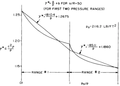
The values of the isentropic functions a and b for air in chemical equilibrium have been calculated for temperatures in the range 300° Κ - 15, 000° Κ and pressures in the range 10~4 - 1 02 atmos- pheres. Acoustic velocity data of the National Bureau of Standards
(12), Logan and Treanor (13), and Hochstim (14) were converted
TECHNOLOGY OF LUNAR EXPLORATION
using Eq. 4, and plotted in the form y * vs. l / p for constant s / R . Over the six decades of pressure considered, the curves behaved quite erratically because of excitation of the various degrees of free- dom of the molecules. Hence in order to obtain 1% or better fit to the data, the constants a, b were obtained for each of twelve p r e s - sure ranges. The straight lines were forced to meet at the bounds of the pressure ranges, so that consistent data are provided for flow field calculations along isentropes. The process of finding a and b is shown in Fig. 2 for the particular value s / R = 50.
The computer programs used to obtain the escape-velocity flow field utilize several tables of thermodynamic data in addition to the
"a and b tables" described above. The compressibility factor Ζ and the modified specific heat ratio y = h/e are required in the shock computations. These have been entered in the form
Ζ(ρ, T ) = + A T . . . + A7T7 [lO]
7 ( P , T ) = BQ + B1T + . . . + Β?Τ7, [ i l ] with the coefficients Ai and Bi determined by least-squares curve
fits to the data of (12) and (15) for various densities. Also required are tables for s(p, p) and Z(p, s ) . These were obtained from the data in (12) and (13).
The thermodynamic data described above are for air in chemical equilibrium. It should be emphasized, however, that the Gravalos flow field method is applicable to any equilibrium gas which is suf- ficiently well-behaved to permit the use of the piece-wise lineariza- tion described above, and for which the required thermodynamic data are available. For example, an unpublished study has been made of the blunt-body flow of a gas representative of the atmosphere of Venus.
Shock Calculation
The calculation of flow in the transonic and supersonic regions r e - quires that shock data corresponding to given free-stream conditions and local shock angle be available. This section will describe the shock analysis, using the notation indicated in Fig. 3. It is assumed that the shock wave is a mathematical discontinuity across which the laws for conservation of mass, momentum, and energy must be satisfied:
^ s P œ V œ siiux = p2 V2 sin (σ - θ) [ l 2 ] 2 2 2 2
^ΞΡ α ο+Ρ ο Λ ο s in a = p2 + p2V2s i n ( σ - θ ) [ ΐ 3 ]
J = Vœ cos σ = V2 cos (σ - θ) [ l 4 ]
5L p . νβ 2 y2 p2 v2 2
ί Ξ = — + — = — + — ' ^
The equation of state for an ideal dissociating gas is assumed to apply:
P2= Z2P2R T2. [16]
The flow field techniques described in this paper may be used for either ideal gases (Z = 1, 7 = C^/C^) or real gases in chemical equi- librium. In the latter case Ζ (ρ, Τ ) and γ (ρ, Τ ) are assumed to be known.
Eqs. 12-16 constitute a set of five equations in the five unknown quantities p2, P2, T2 ' V2 ' ^" T^e m e t^ o d of solution which has been used was developed by Langelo (16). Eqs. 12-14 are substituted into Eq. 15 to eliminate the variables V2, P2> Θ; there results a quadra- tic equation for the density ρ :
lJ) 4 -
rA -
* P2- | W
= ο [17]2 - ι \ y2 -1 /
Using a first approximation for y2, which may be taken as y^, Eq.
17 yields the density p2. The larger root is the correct one for well- behaved real gases such as air (17). Eqs. 12 and 13 may be com- bined to give the pressure p2*.
A new approximation to the temperature is determined from Eq. 16, using an appropriate loop for the product Z2T2. An improved value of y2 is then obtained from the least-squares curve fits described e a r l i e r . The process is repeated, starting from Eq. 17, until the temperature is constant to four significant figures. The values of Τ , ρ , and ρ on the final iteration are used, together with V and
TECHNOLOGY OF LUNAR EXPLORATION
θ obtained from Eqs. 12 and 14:
P2
[19]
θ = σ - cos - ι σ [20]
Transonic Region
The flow over a blunt-nosed supersonic body is characterized by the occurrence of a detached shock wave and regions of subsonic and su- personic flow separated by a sonic line (or surface). Solution of the subsonic flow region is of considerable interest in itself, and is e s - sential for the calculation of the supersonic flow since the location of the sonic line is not known beforehand. The iterative method of solu- tion used in the present calculations, which was developed by Grava- los et al. (6, 7), will be discussed in this section. This "transonic method" yields the flow variables throughout the inviscid subsonic and transonic regions, including the body pressure distribution, shock shape, and sonic line location.
Referring to Fig. 4, the body is specified by a series of points (x^,
ri ) » together with body slopes and curvatures at these points. Length dimensions are referred to the nose diameter, or some other r e f e r - ence length, while the flow variables are treated in dimensional form, using engineering units. Initial estimates of the static pressures on the body at (x^, r p are chosen. Lacking better information, the modified Newtonian values
2 2
ρ = p^ sin θ + pœ cos θ [ 2 l ]
may be used. An initial estimate of the shock shape is also required, in the form of a fifth order polynomial in r2:
2 0 Tool 1
χ = aA + a r + . . . ar r I 22J
s O l s 5 s L
The governing equations are solved in the streamline-normal coor- dinate system depicted in Fig. 4. If we define the value of the stream function by ψ = 7Tr2pû0 V , the mass flow rate in the stream tube bounded by the mt n and m - lL n streamlines is
φ - ψ = 7 7 ΔΠ ( Γ ρ V + r ρ V ) , [23]
m m-1 m m m m-1 m-1 m-1 L J
where
r = r + (cosG + cos6Δ η ). Γ24]
m m-1 2 m m-1
The equation for conservation of momentum normal to the stream- line,
2 ön ~ R '
is treated in the finite-difference form
[25]
/ 2 2
. I ρ
V ρ V ,Δη m m m-1 m-1 ι Γ ο / >Ί
\ m m-1
Eq. 6 relates pressure and density variations along the streamline.
Eq. 8 relates pressure, density, and velocity along the streamline.
The parameters Κ and C are obtained from the oblique-shock data for the given streamline, and in general they change dis continuously at points where the streamline being considered crosses pressure breaks in the y * fits. Finally, the Mach number is given by Eq. 9.
The procedure used in the transonic flow calculation will now be described. From the assumed body pressures and the known nor- mal-shock entropy, Eq. 6 is solved for density at the body points.
The velocity and Mach number at the body points are then found from Eqs. 8 and 9 respectively.
The calculation of each streamline other than the body streamline must be performed a number of times, using successive approxima- tions to the radius of curvature R of the streamline. Consider, for instance, the calculation of the m ^1 streamline away from the body.
It is specified in terms of the free-stream mass flow Δ φ in the streamtube bounded by it and the m - lt n streamline. A set of Δ ψ values, which define the starting radial coordinates of the stream- lines to be computed, is required for the transonic calculations.
Consider the mesh point which is at the intersection of the m ^1 streamline with the rfi1 normal. From continuity, Eq. 23, an esti- mate of the streamtube width Δ η is
2ττρ V r L J
m-1 m-1 m-1
T E C H N O L O G Y O F LUNAR EXPLORATION
From Eq. 26, an estimate of the pressure at this mesh point is
» ,
v,
2ρ , p -> Δ„ • - ' [2 8] m m-1 R
m-1
To improve the accuracy of the calculation of pm, improved values of pm, V , and Δη are obtained using Eqs. 6, 8 and 23. A conver- gence criterion specifies the accuracy desired in determining the streamline location. Then the succeeding points n+1, n+2, . . . along the streamline are calculated in an identical manner. After the en- tire streamline has been found, it is necessary to repeat the calcu- lation at each mesh point, using successively improved values of Rm. These are obtained by parabolic fit of the points n-1, n, n+1 found during the previous calculation of this streamline.
•fV»
As each streamline at the η normal is obtained, a continuity check is made. This is done by comparing the radial coordinate
rm ° ^ ^ e m ^ s t r e a rlQm e with the radial coordinate ( rg)m which corresponds to the mass flow between this streamline and the body.
As may be seen from Fig. 4, rm > ( rg)m for points within the shock layer. When some streamline c is reached at which the condition
rc = (rs ) *s m e* *° withi11 a specified accuracy, the mass flow a- cross normal η is equal to the mass flow through the shock. This defines a "continuity point" (x_, r ) which terminates normal n. The
c c
continuity points for all normals, taken together, provide essential information for subsequent iterations. In general there is a differ- ence between the pressure as determined using Eq. 26 and the p r e s - sure obtained from the oblique shock wave solution, using the as- sumed shock shape. Also, the continuity points do not fall exactly on the assumed shock wave. These e r r o r s provide criteria for ad- justing body pressure and shock shape. Usually from five to twenty attempts are required to effect convergence.
Solutions which have been obtained during the four years of use of the transonic flow field method at GE-MSVD include some 40 r e a l - air cases at various velocity-altitude conditions, 7 ideal gas cases (y = 1.4, 1.67), and 2 cases corresponding to certain shock tunnel conditions. The majority of these solutions have been for spherical forebodies, though a few have been for Apollo-type blunt bodies. The method works well in the hypersonic and moderate supersonic speed ranges. The choice of altitude is limited only by the assumption of continuum flow and use of the equation of state discussed e a r l i e r .
The transonic method gives shock layer results in both the sub- sonic flow and a portion of the supersonic flow. The calculations can be carried without difficulty to body stations at which the flow is su- personic. Initial data along a "transonic normal" are thus available for the calculation of the supersonic flow over the remainder of the body.
Supersonic Region
The supersonic flow calculation proceeds from initial data supplied by the transonic calculations just described. It is done by the usual method of characteristics, e . g . Ref. 1, pp. 253-257, taking p r e s - sure and flow angle as the dependent variables. Flow properties are calculated at the mesh points of left-running characteristics ^+ and right-running characteristics The equations governing changes in ρ and Θ,
d /+ p v2 d i+ Mr
d9 \ M " - 1 dp s i n e Γ Ί
AI PV dJfc
are treated in finite-difference form. The computer program which was devised calculates along right-running characteristics from the input line or the shock to the body. For the calculation of field points Eqs. 29 and 30 are used. Shock points require Eq. 29 together with the oblique shock solution. Body points require Eq. 30 and the given body shape. For these calculations Eqs. 6, 8 and 9 give ρ, V and M for successive improvement of the parameters in Eqs. 29 and 30.
NUMERICAL RESULTS
Since the main purpose of the study reported here was to investi- gate the dynamic and thermodynamic effects peculiar to blunt-body flow at extremely high speeds, it was decided to limit the calcula- tions to a single body configuration, the hemisphere-cylinder.
The free-stream conditions were chosen to be 36, 000 ft/sec v e l o - city and 100, 000 ft. altitude. For purposes of comparison, p r e s - sure and shock shape data from six other hemisphere-cylinder flow fields will be presented also. See Table I for the assumed flight con-
TECHNOLOGY OF LUNAR EXPLORATION
ditions. The 1959 ARDC model of the earthTs atmosphere (18) was used for the free-stream properties corresponding to the specified altitudes.
Earlier theoretical work dealing with supersonic flow about hemi- sphere-cylinders will be briefly reviewed, in order to set the frame- work for the new results to be given here. Feldman (19) calculated a real-gas flow field by the method of characteristics, starting from transonic data calculated by the method of Belotserkovskii using y - 1. 2. Detailed results of the shock layer structure were given, show- ing the existence of a large low-density, high-entropy region near the cylinder. Van Hise (20) obtained ideal-gas flow fields for hemi- sphere-cylinders using a sonic cone starting solution. He gave r e - sults for body pressure distributions and shock shapes at several Mach numbers. Vaglio-Laurin and T r e l l a (21) calculated flow of equilibrium air and ideal gas about a hemisphere-cylinder at Mach numbers ranging from 7. 7 to 22. Seiff and Whiting (22) derived a method of determining flow in the subsonic and supersonic regions using the continuity equation together with an assumed shock shape.
Oblique Shock Wave
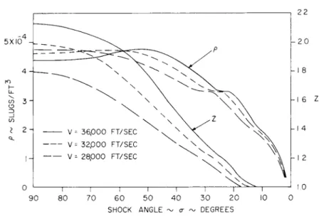
The conditions immediately following an oblique shock wave have been calculated for shock angles of 90° > σ > sin""1 l / Mœ. Flight speeds of 28, 000 ft/sec, 32, 000 ft/sec and 36, 000 ft/sec at 100, 000 ft. altitude were assumed. Results for density and compressibility are shown in Fig. 5. At shock angles for which Ζ 1. 2 the density curves have inflections associated with oxygen dissociation. Results at lower velocities have shown a characteristic increase of density as the shock strength is increased. We see from Fig. 5, however, that for escape velocity shocks the density reaches a maximum at ap- proximately σ = 50° and falls to a somewhat smaller value at the nor- mal shock. The oblique shock results at = 36, 000 ft/sec have been used as input data for the transonic and supersonic flow field calculations described below.
Spherical Nose
The transonic flow field method has been used to calculate the sub- sonic and transonic region of flow about a hemispherical forebody at a velocity of 36, 000 ft/sec and an altitude of 100, 000 ft. The thermo- dynamic tables and oblique shock data described earlier were used as input to the calculations. Twelve normals were originated at the
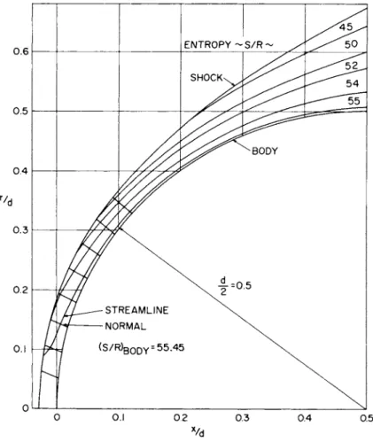
body, at the stations θ: 84° (5°) 29°. In the present instance only four iterations were required for satisfactory convergence, which was considered to have been obtained when the pressures at the con- tinuity points were within 1% of the corresponding oblique-shock pressures and the locations of the continuity points agreed with the final assumed shock shape. Four streamlines crossed the first nor- mal before it reached the shock, while 31 streamlines crossed the twelfth normal. The supersonic characteristics calculation was be- gun using data from the eighth normal of the transonic solution. The variables ρ, ρ, V, Μ, θ were plotted, and eighteen points (x, r) were selected at which to read the input data. The computer calculation gave results in the supersonic region of the nose and downstream along the cylinder. Fig. 6 shows the locations of the transonic nor- mals and several of the streamlines.
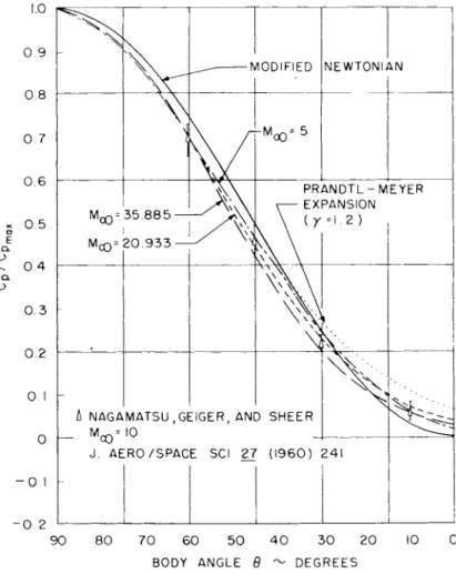
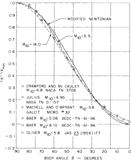
The pressure distribution over most of the hemisphere has been found to be significantly lower than predicted by the modified New- tonian theory expression
C / C = s i n29 . Ρ Ρ
max
The comparison is shown in Fig. 7e Also shown are the converged pressure distributions, computed by Gravalos' method, for several other real-gas flow fields. The flow field results deviate immedi- ately from the modified Newtonian prediction, though the sparseness of mesh points near the stagnation point introduces some e r r o r in this vicinity. At a station one-half of the distance around the sphere there appears to be a definite trend away from Newtonian theory as the free-stream velocity increases, in agreement with calculations of Vaglio-Laurin and T r e l l a (21) over a smaller velocity range. For the escape-velocity case Eq. 31 overpredicts the pressure coefficient by as much as 25% at body stations of approximately 30°. The shock tunnel data of Nagamatsu, Geiger, and Shear (23) at a Mach number of ten, shown in Fig. 7 for comparison, tend to substantiate the flow field results. The data are from runs at stagnation temperatures of 1400°K to 5300°K, but the nozzle flow may not have been in chemical equilibrium at the higher stagnation temperatures. Experimental data for sphere pressures at real-gas flow conditions nearer to those assumed in the flow field calculations are not available.
In order to assess the relative importance of real-gas effects upon the sphere pressure distribution, and to provide a comparison of
[31]
TECHNOLOGY OF LUNAR EXPLORATION
flow field results with experimental data, several ideal gas flow fields have been computed by Gravalos' method. The body pressures are presented in Fig. 8. The flow field results and the data of Baer (24), Machell and O'Bryant (25), and Crawford and McCauley (26) ap- pear to be in agreement that Newtonian theory somewhat o v e r e s t i - mates the pressure coefficient on much of the sphere. The same qualitative effect is found in the inverse blunt-body calculations by Van Dyke and Gordon (27) and Vaglio-Laurin and Trella(21)0 On the other hand, the data of Oliver (28) and Julius (29) agree very well with the Newtonian prediction.
It is not clear from the flow field results shown in Fig. 8 whether the continuing effect of velocity changes upon pressure coefficient noted for the real-gas cases occurs for ideal gases also. This could probably be determined by calculating ideal-gas flow fields at higher Mach numbers by Gravalos1 method. The results of Van Dyke and Gordon (27) indicate that the ideal-gas pressure coefficient is v i r - tually independent of Mach number for Mach numbers of 10 or greater.
From the above considerations it is concluded that the velocity trend of Cp/Cp shown in Fig. 7 is a real-gas effect attributable to m o -
max
lecular dissociation. The principle of Mach number independence de- rived for ideal gases (Ref. 1, pp. 24-26) is not valid for real airflow fields at these velocities, at least with regard to surface pressure coefficient.
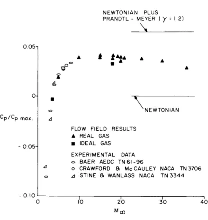
Fig. 9 summarizes a number of flow field results for the pressure coefficient ratio at the shoulder (Θ = 0 ° ) . The ratio has been found to be approximately 0.04 for free-stream Mach numbers of about 15.
For lower Mach numbers it is significantly less, and there is a slight downward trend at higher Mach numbers. Newtonian impact theory, of course, predicts a pressure coefficient of zero at the shoulder. A Prandtl-Meyer expansion continuation of the Newtonian curve, start- ing at the location where the two methods have the same pressure gradients and using an average y of 1. 2, overestimates the shoulder pressure coefficient by a factor of two for the escape velocity case»
The shock-wave and sonic line locations are shown in Fig. 10 for four of the flow fields. A s the free-stream velocity is varied, the extent of the subsonic flow region is strongly affected by both the change in shock detachment distance and the change in sonic line location.
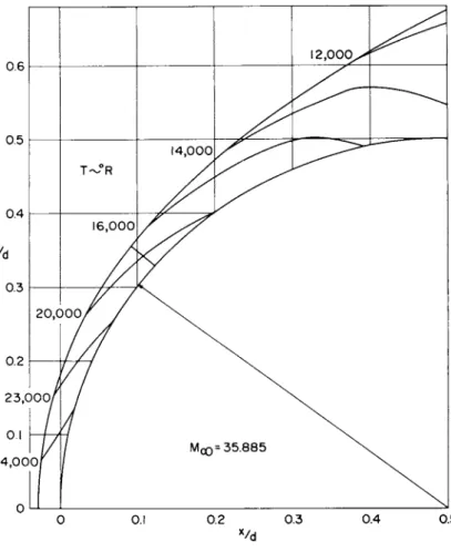
In order to present flow field data in a useful and illustrative form, search-interpolation programs were written which give constant- property lines. F i g s0 11 and 12 show contours of constant density and temperature in the shock layer about the spherical nose. The density curves in the stagnation region behave oddly because of dissociation phenomena, as discussed earlier in connection with the oblique shock conditions. Downstream of the stagnation region, the density in- creases from the body to the shock. The temperature falls from the stagnation value of 24, 400°R to approximately 14, 000°R at the tan- gency point with the cylinder. Its variation from body to shock is 25% or less.
Cylindrical Afterbody
The real-gas supersonic flow field at Mach 35, 885 was calculated by the method of characteristics. The computed body pressures from the tangency point x / d = 0. 5 to x / d = 15 are shown in Fig. 13.
The high pressure level of the escape-velocity case and its rather gradual decay toward the free-stream value are noteworthy. A v a i l - able experimental data are also shown, along with pressure distri- butions from six additional flow fields. The cylinder pressure data of Baer (24) at Mach numbers of 3, 4. 03, 5. 06 and 8.10 at a stagna- tion temperature of 100°F and Reynolds number per inch of 4 X 10^
agree well with the flow field calculations at Mach numbers of 30 5, 5. 0 and 8. 0. These results, together with those in Fig. 9, show the presence of overexpansion near the shoulder. Unfortunately no ac- curate data for pressures on a spherically-blunted cylinder are a- vailable for Mach numbers above about eight.
An attempted correlation of experimental and theoretical results for pressures along the cylinder, using the cylindrical blast-wave parameter (2), is shown in Fig. 14. Axial stations are from two to fifteen nose diameters from the stagnation point, regardless of Mach number, in order to illustrate the range of applicability of the blast- wave theory. At high Mach numbers the equation given by the sec- ond-order theory for y = 1.4,
overpredicts the pressures near the nose by about 75% but further downstream it gives good results. At intermediate Mach numbers
x / d [ 3 2 ]
00
TECHNOLOGY OF LUNAR EXPLORATION
the agreement if fairly good for x / d from two to fifteen. At low Mach numbers the blast theory is not applicable.
Feldman's calculations (19) by the method of characteristics for the case of a hemisphere-cylinder at a velocity of 17, 500 ft/sec and an altitude of 60, 000 ft. were carried to an axial distance x / d = 50. His results also indicate that the blast-wave theory overpredicts the c y l - inder pressure somewhat. The characteristics calculations reported by Van Hise (20) for an ideal gas with y = 1„ 4 agree well with the c o r - relation shown in Fig. 14 when the blast parameter is 0. 01 or great- e r . When it is less than 0.01 his results follow the second-order blast-wave prediction rather than the present ideal and real gas flow field pressures.
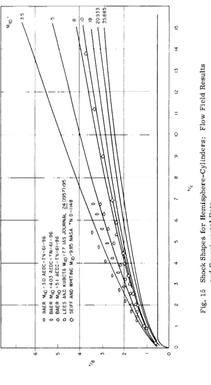
Shock shapes obtained by theory and experiments are compared in Fig. 15. The data of Baer (24) at Mach 3 and 4 bracket the flow field result for Mach 3. 5 as would be expected. Flow field results at Mach numbers of 5 and 10 agree well with experimental data, al- though the tests were conducted at ideal-gas conditions whereas the calculations were for equilibrium air.
A correlation of the theory and data according to the second-order blast-wave analogy is shown in Fig. 160 The suggested equation (2), assuming y = 1„4,
predicts Mach number independence for shock shape, the last factor being unity at high Mach numbers. Eq. 33 underpredicts the radial shock coordinate by about 5%, on the average. For the escape-ve- locity case the agreement is excellent.
Details of the flow over the cylinder are shown by constant-lines plots in Figs. 17 and 18. The constancy of pressure (at given axial station) across half the shock layer thickness is a notable feature of the flow. The high temperature and low density near the cylinder's surface are due to the fact that the gas in this region has passed through the strong portion of the bow shock wave. The calculated shock-layer profiles of pressure and temperature at given axial sta-
1_
2
1_
2 r / d
= 0.795
tion appear to be in qualitative agreement with Feldman's results (19).
CONCLUDING REMARKS
The escape-velocity flow field results which have been presented in this paper are valid for an altitude of 100, 000 ft0 Although exact scaling of the results to other altitudes is not possible for air in chemical equilibrium, experience in calculating other hypersonic flow fields has shown that the following approximate rules are suf- ficiently accurate for most engineering purposes. To scale density (or pressure), multiply the present results by the ratio of ambient densities (or pressures) at the two altitudes. Temperature, velocity, Mach number and flow angle should be left unchanged. These rules apply only to dissociated hypersonic flow. For ideal gas flow fields at a given Mach number the variables ρ, ρ, Τ, V scale exactly by the ratios of the corresponding free-stream properties, while M and θ remain unchanged.
A major limitation on the validity of the results which have been presented is the neglect of fluid viscosity. Whereas the inviscid flow field predicts a region of high velocity, high temperature, low den- sity dissociated gas near the cylinder, it is well-known that the ab- sence of slip at the wall, together with wall cooling, results in a large velocity gradient and a boundary layer of relatively cool high- density flow. The boundary layer on the cylinder at 100, 000 ft. al- titude is probably thin and turbulent, and its effects upon the body pressure distribution, the shock shape, and most of the flow field should be minor.
A second important assumption, that of chemical equilibrium, is probably valid in the low-velocity region near the spherical nose b e - cause of the relatively large residence times and the high tempera- tures and pressures there. Downstream, however, particularly in the low-density region adjacent to the cylinder, deviations from equi- librium may occur. Large deviations would be expected for flow fields at altitudes of approximately 200, 000 ft. or higher, but the ef- fect may be minor at the altitude of 100, 000 ft. for which the present results were obtained.
Estimates of the equilibrium-flow electron densities in the ionized layer about the hemisphere-cylinder may be readily made using air composition data (30). The electron density at the stagnation point is found to be approximately 7 Χ 1 01 7 c m "3. At ten nose diameters
TECHNOLOGY OF LUNAR EXPLORATION
downstream, the value near the cylinder's surface is 6 X 1 0± o c m ~ ° . By way of contrast, the corresponding values for the flow field at 21, 000 ft/sec velocity and 100, 000 ft. altitude are 3 X 1 01 5 cm""3 and 7 X 1 01 2 c m "3. The greatly increased electron densities associated with re-entry at escape velocity may be of considerable importance in communication and detection problems.
The numerical results which have been presented were calculated using computer programs for the supersonic flow about a smooth blunt body of revolution at zero angle of attack. Brief mention should be made of several compatible programs which have been developed
subsequently at GE-MSVD. One program calculates the Prandtl- Meyer expansion at a sharp convex corner of a blunt body, and the flow downstream of it. Another obtains the secondary shock wave r e - sulting from a sharp concave corner, together with the flow down- stream of it. Still a third calculates the flow field at arbitrarily small angle of attack by a perturbation method. The problem of cal- culating flow fields which include intersecting bow and secondary shock waves is now being programmed for the IBM 7090 computer.
Finally, it should be mentioned that the flow field analyses and p r o - grams are applicable to both two-dimensional and axially-symmetric flows. For clarity and conciseness this paper has been limited to axially-symmetric cases.
ACKNOWLEDGMENTS
The flow field analysis used to obtain the results in this paper was developed by F. G. Gravalos, with the collaboration of I . H. Edelfelt and H. W. Emmons. J. W. Friedhof er programmed the equations for the IBM 704 digital computer. The numerical results were ob- tained with the assistance of M r s . M . E. O'Brien and M r s . S. F.
Hill, whose help is gratefully acknowledged.
NOTATION
c = equilibrium speed of sound d = nose diameter
e « internal energy
h = enthalpy; also, altitude ρ " static pressure
r » radial coordinate
s - entropy; also, distance along streamline
χ = axial coordinate / ^ _ , 2 \ C D
C = pressure coefficient (p-p^)/-— Pœ^t
P _ ^ D/Dt s ô/dt + V' V
R a specific gas constant for undissociated mixture;
also, local radius of curvature of streamline S r = shock point
Ζ = compressibility factor, ρ = Z p R T
i+ = coordinate along left-running characteristic 4~ = coordinate along right-running characteristic 7 * specific heat ratio C p / Cy
Δ η = incremental distance out transonic normal Αφ - mass flow through steamtube
Subscripts
c = continuity point m » number of streamline s « refers to shock wave max = stagnation
REFERENCES
1 Hayes, W. D . , and Probstein, R0 F . , Hypersonic Flow Theory, Academic P r e s s , N0 Y0 , 1959.
2 Lukasiewicz, J., "Blast-Hypersonic Flow Analogy Theory and Application", ARS Preprint No. 2169-61, October 1961.
3 Van Dyke, M . D . , " A Study of Hypersonic Small-Disturbance Theory", NACA Report 1194, 1954.
4 Uchida, Se, and Yasuhara, Μ . , "The Rotational Field Behind a Curved Shock Wave Calculated by the Method of Flux Analysis " , IAS Journal, V o l . 23, No. 9, September 1956, pp. 830-845.
5 Belotserkovskii, Ο. Μ . , "Flow with a Detached Shock Wave about a Symmetrical P r o f i l e " , Jour. Appl. Math, and Mech. ( P M M ) , V o l . 22, No. 2, 1958, ppe 279-296.
6 Gravalos, F. G . , "Supersonic Flow About a Blunt Body of R e v o - lution", in Advances in Astronautical Sciences » V o l . 2 ( P r o c 4th Annual Meeting, A m e r , Astron. S o c , December 1957). Plenum P r e s s , Ν . Υ . , 1958.
TECHNOLOGY OF LUNAR EXPLORATION
7 Gravalos, F0 G . , Edelfelt, I . Η . , and Emmons, H. W . , "The Supersonic Flow About a Blunt Body of Revolution for Gases at Chem- ical Equilibrium", 9th Annual Congress of International Astronautical
Federation, Amsterdam, August 1958.
8 Garabedian, P . R . , and Lieberstein, H, M . , "On the Numerical Calculation of Detached Bow Shock Waves in Hypersonic Flow", IAS Journal, V o l . 25, No. 2, February 1958, pp0 109-118.
9 Van Dyke, M . D0, "The Supersonic Blunt-Body Problem - R e - view and Extension", Jour. Aero/Space S e i . , V o l . 25, No. 8, August 1958, pp. 485-496.
10 Vaglio-Laurin, R0, and F e r r i , A . , "Theoretical Investigation of the Flow Field About Blunt Nosed Bodies in Supersonic Flight", Jour. Aero/Space S e i . , V o l . 25, No. 12, December 1958, ppe 761- 770«,
11 Vaglio-Laurin, R . , "On the P L K Method and the Supersonic Blunt-Body Problem", J. Aero/Space Sci„, V o l . 29, No. 2, Febru- ary 1962, pp0 185-206.
12 Hilsenrath, J. et a l . , Tables of Thermal Functions of Gases, NBS Circular 564, November 1955.
13 Logan, J. G. and Treanor, C. E0, "Tables of Thermodynamic Properties of A i r from 3000°K to 10, 000°K at Intervals of 100°K", Cornell A e r o . Lab. Report No. BE-1007-A-3, January 1957.
14 Hochstim, A . R . , "Gas Properties Behind Shocks at Hyper- sonic Velocities: I I I . Tables of Thermodynamic Properties of A i r " , Convair ZPh-004, August 1958.
15 Hilsenrath, J. and Beckett, C. W0, "Tables of Thermodynamic Properties of A r g o n - F r e e A i r to 15, 000°K", AEDC T N 56-12, Sep- tember 1956.
16 Langelo, V0 Α . , "Flow Across a Shock Front", General E l e c - tric Company Report TIS R56SD135, August 1956.
17 Hammit, Ae Ge, "Further Comments on 'Mach Line Determin- ation for A i r in Dissociation Equilibrium'", Jour. Aero/Space S e i . , Readers' Forum, V o l . 28, No. 8, August 1961, pp. 659-660.
18 Minzner, R. A „ , Champion, Kc S. W. and Pond, H0 L0, "The ARDC Model Atmosphere, 1959", A i r Force Surveys in Geophysics, No. 115, AFCRC-TR-59-267, August 1959.
19 Feldman, S., "Numerical Comparison Between Exact and A p - proximate Theories of Hypersonic Inviscid Flow Past Slender Blunt- Nosed Bodies", ARS Journal, V o l . 30, No. 5, May 1960, pp. 463- 468.
20 Van Hise, V . , "Analytic Study of Induced Pressure on Long Bodies of Revolution with Varying Nose Bluntness at Hypersonic Speeds", NASA Technical Report R-78, 1960.
21 Vaglio-Laurin, R . , and T r e l l a , Μβ, " A Study of Flow Fields About Some Typical Blunt-Nosed Slender Bodies", Polytechnic In- stitute of Brooklyn, Report No. 623, December 1960.
22 Seiff, Α . , and Whiting, Ε. Ε . , "Calculation of Flow Fields from Bow Wave Profiles for the Downstream Region of Blunt Nosed Circu- lar Cylinders in Axial Hypersonic Flight", NASA T N D-1147, Nov- ember 1961.
23 Nagamatsu, H. T . , Geiger, R. Ε . , and Sheer, R0 Ε . , Jr.,
"Real Gas Effects in Flow Over Blunt Bodies at Hypersonic Speeds", J. Aero/Space S e i . , V o l . 27, No. 4, April 1960, pp. 241-251.
24 Baer, A . L . , "Pressure Distributions on a Hemisphere Cylin- der at Supersonic and Hypersonic Mach Numbers", AEDC T N 61-96, August 1961.
25 Machell, R. Μ . , and Ο'Bryant, W. T . , "An Experimental In- vestigation of the Flow Over Blunt-Nosed Cones at a Mach Number of 5, 8", CALCIT Hypersonic Research Project Memo No. 32, June 1956.
26 Crawford, D. Η . , and McCauley, W. D . , "Investigation of the Laminar Heat-Transfer Characteristics of a Hemisphere-Cylinder in the Langley 11-Inch Hypersonic Tunnel at a Mach Number of 6.8", NACA T N 3706, July 1956.
27 Van Dyke, M . D . , and Gordon, Η . , "Supersonic Flow Past a Family of Blunt Axisymmetric Bodies", NASA Technical R e p o r t R - l , 1959.
TECHNOLOGY OF LUNAR EXPLORATION
28 Oliver, R. E . , T TAn Experimental Investigation of Flow About Simple Blunt Bodies at a Nominal Mach Number of 5.8", J. A e r o . Sei., V o l . 23, NO« 2, February 1956, pp. 177-179.
29 Julius, J. D0, "Experimental Pressure Distributions Over Blunt T w o - a n d Three-Dimensional Bodies Having Similar C r o s s - Sections at a Mach Number of 4.95", NASA TND-157, September 1959.
30 Hilsenrath, Je and Beckett, C. W . , Addendum to Ref„ 15, unpublished.
31 L e e s , L0, and Kubota, Τ . , "Inviscid Hypersonic Flow Over Blunt-Nosed Slender Bodies", IAS Journal, V o l . 24, N o . 3, March 1957, pp. 195-202.
32 Seiff, Α . , and Whiting, Ε. E . , " A Correlation of the Bow-Wave Profiles of Blunt Bodies", NASA T N D-1148, February 1962.
33 Stine, Η. Α . , and Wanlass, Κ . , "Theoretical and Experimental Investigation of Aerodynamic Heating and Isothermal Heat-Transfer Parameters on a Hemispherical Nose with Laminar Boundary L a y e r at Supersonic Mach Numbers", NACA T N 3344, December 1954.
T A B L E I
ASSUMED FREE STREAM CONDITIONS AND
C A L C U L A T E D S T A G N A T I O N P R E S S U R E A N D D R A G C O E F F I C I E N T
M V
oo (ft/sec)
h (ft)
P o o . ( l b / f t2)
C ρ
max
3β5 (ideal gas) 1.778 .99
5.0 5080 25,000 786.3 1.815 .96
8.0 (ideal gas) 1.826 .88
10.0 9681 40,000 393.1 1.871 .95
18.0 (ideal gas) 1.837 .878
20.933 21,000 100,000 23.085 1.921 .925 35.885 36,000 100,000 23.085 1.926 .880
BOW
- _ L _ _ J ^
Fig. 1 Sketch of Supersonic Flow About a Blunt Body
7*-f + b F O R s / R = 5 0
( F O R F I R S T T W O P R E S S U R E R A N G E S )
01 .1 p I P o /
Fig. 2 Representation of A i r Properties
SHOCK SHOCK / m UPSTREAM / DOWNSTREAM / J>/ / Lr^^y ^ BODY f\ M°° / ^^^d/^ Fig. 3 Oblique Shock Notation Fig, 4 Notation for Transonic Flow Field Calculations TECHNOLOGY OF LUNAR EXPLORATION
2 2
Fig. 5 Density and Compressibility Behind Oblique Shock Waves in A i r ( h = 100,000 f t . )
TECHNOLOGY OF LUNAR EXPLORATION
0 6 E N T R O P Y - S / R - / 7 ^ °
S H O C K ^
^ ^ ^ ^ ^ ^
0.3
0.2 \ ^ γ=0 . 5 y / T L - - — - S T R E A M L I N E
NORMAL \ . 0.1 — ( S / R ) B 0D Y = 55.45 \ v
0 0.1 0 2 0.3 0.4 0.5 Vd
Fig. 6 Transonic Normal-Streamline Grid and Streamlines in Supersonic Region of Spherical Nose
_Q 2 1 1 ι 1 ι 1 1
90 80 70 60 50 40 30 20 10 0 BODY ANGLE θ ~ DEGREES
Fige 7 Pressure Distributions on Spheres: Real Gas Flow Fields and Experiment
TECHNOLOGY OF LUNAR EXPLORATION
0.6 0.5 0.4 0.3
0 . 2
0 . 1
0
- 0 . 1
- 0 2
ο CRAWFORD AND Mc CAULEY
Μ 6 . 8 Ν AC Δ TN 3 7 0 6
ο JULIUS Μφ^.θδ NASA TN D - 157 Û MACHELL AND 0 ' BRYANT
GALCIT MEMO =* 3 2
ο BAER Μ^δ.06 AEDC - TN - 61 - 9 6
"ο BAER MQ Q - 8 10 AEDC-TN - 6 1 - 9 6 ο OLIVER Μ ^ δ . β JAS 2 3 ( 1 9 5 6 ) 1 7 7
9 0 8 0 7 0 6 0 5 0 4 0 3 0 2 0
BODY ANGLE Θ ~ DEGREES
10
Fig. 8 Pressure Distributions on Spheres: Ideal Gas Flow Fields and Experiments
N E W T O N I A N P L U S P R A N D T L - M E Y E R ( / = 1.2)
_ \ ι
0 0 5 η
C p / C p mx a
0.05H
N E W T O N I A N
F L O W F I E L D R E S U L T S A R E A L G A S
• I D E A L G A S
E X P E R I M E N T A L D A T A ο B A E R A E D C T N 6 1 - 9 6
ο C R A W F O R D 8 M c C A U L E Y N A C A T N 3 7 0 6 Δ S T I N E 8 W A N L A S S N A C A T N 3 3 4 4
• 0 . 1 0 1
Ί ο 2 0 I 3 0 I — 4 0
100
Fig. 9 Shoulder Pressure Coefficients on Hemisphere-Cylinders
TECHNOLOGY OF LUNAR EXPLORATION
6 9 — — ^
6 6
y~ y/~ y
6 3
y^ y/~ -y^-
6 0
y^ y/~
Mc 0 = 3 5 / ^ yf × y /
/ / f^^y/ ^^^^^
. 3 9 / / / y / /
SPHERE09 4—I—É—I—/
0 6 1
1 j
0 3 J
0I I — I — I — I — I
-0.1 0 0 1 0 . 2 0 . 3
Fig. 10 Shock Shapes and Sonic Lines for Four Flow Fields
Fig. 11 Lines of Constant Density for Sphere at 36, 000 ft/sec
TECHNOLOGY OF LUNAR EXPLORATION
Fig. 12 Lines of Constant Temperature for Sphere at 36, 000 ft/sec
30
10
3
Moo -
35.885
D \
2 0 9 3 3
^ 1 8 . 0
ô
0
0 0 0 ^^--^
^^^tloZT^ - 5 0
10.0
° ° ° 3 5
EXPERIMENTAL DATA :
-tf=
° BAER Mco = 3.00 A E D C - T N - 6 1 - 9 6 0 BAER Μ ο ο = 4 0 3 AEDC - T N - 6 1 - 9 6 o BAER MÇQ = 5 0 6 A E D C - T N - 6 1 - 9 6 O BAER Mco=8IO AEDC — TN-61 - 9 6 D LEES AND KUBOTA Μ φ = 77 JAS 24 (1957) 195
0 I 2 3 4 5 6 7 8 9 10 II 12 13 14 15 Fig. 13 Pressures on Hemisphere-Cylinders: Flow Field Results
and Experimental Data
100.0 ι 1 1 j 1 1 >v
x/
d = 2 TO 15 \ ^Ρ/çΛΛ =0 067 M°° C° t0,44 / PCO x/d M œ= 35 885 ^\ \^ LUKASIEWICZ, ARS PREPRINT 2169 -61 100 1 EXPERIMENTAL DATA % 0 BAER M °° =506 AEDC-TN-61-96 00 ° BAER M°° =8 10 AEDC "TN"61 "96 ^^r&àsv D LEES & KUB0TA M00 = 77 JAS 24(1957)195 20 933 ^P °
,0o.i I
1 1 1 1 1 0001 .001 .01 I I 10 100 lui 2 ρ 1/2 MoO CD Fig. 14 Body Pressure Correlation Based on Blast-Wave Parameter TECHNOLOGY OF LUNAR EXPLORATIONι I ι
j ι
I I j M<o = Ij
^ ^^^^ 3.5 ο BAER MQQ = 3.0 AEDC-TN-61-96 0 BAER MQQ =4.03 AEDC-TN-61-96 ; 5 5 - Τ BAER MoQ =5.1 A^DC-TN-6l-96 } ^^^^ D LEES AND KUBOTA ΜΓΟ=7.7 IAS JOURNAL 24(1957)195: ^^^^ ^^^^^ Ο SEIFF AND WHITING Mc0 = 9.85 NASA TN D-II48 ^^^^ ! ^-^^^"^^ 8 0 I 2 3 4 5 6 7 8 9 10 II 12 13 14 15 Fig. 15 Shock Shapes for Hemisphere-Cylinders: Flow Field Results and Experimental DataTECHNOLOGY OF LUNAR EXPLORATION
10
Ol
Μβ« 3 5
x/d = 2 TO 15
5 . 0
1 8 . 0 > - ^ ^ ^ ^ 1 20 933
35 8 8 5 . ^
—
*'ά \L2 LUKASIEWICZ / MJQ2 C01 /2 / ARS PREPRINT 2169-61
EXPERIMENTAL DATA
£>BAER MJQ 5 06 AEDC - TN
D LEE S & ΚυβΟΤΑ MQ 7.7 JA
0 SEIFF 8 WHITING 9 85 - 6 1 - 9 6 S 24 (1957) 195 NASA TN D - I I 4 8
001 Ol I M 2 r 1/2
M( 0 CD
Fig. 16 Shock Shape Correlation Based on Blast-Wave Parameter
MQO = 35.885 Ρ ~ LBS/ FT2 3 — 0
f
600 400 " -10 I 2 3 4 5 6 7 8 9 10 II 12 13 14 15 16 x/d Fig. 17 Lines of Constant Pressure for Cylinder Mco = 35.885 Τ rv, eR SHOCK 1 — I - POOP ^ --BS ". -4000 r/d ^ ,—"""^ίΐ " ^! '— 8000 J Λ1 -»3,ΟΟθ' 1 -10 I 2 3 4 5 6 7 8 9 10 II 12 13 14 15 16 x/d Fig, 18 Lines of Constant Temperature for Cylinder