dynamic applications
Laszlo Kazup
pand Angela Varadine Szarka
Research Institute of Electronics and Information Technology, University of Miskolc, Egyetemvaros, H-3515 Miskolc, Hungary
Received: December 31, 2019 • Revised manuscript received: April 18, 2020 • Accepted: June 4, 2020 Published online: March 1, 2021
ABSTRACT
This paper introduces research on magnetic fields with special attention to developing a new method for braking fast-changing alternating movements. This work is part of a research project aiming to find the most efficient and accurate method for development of linear magnetic brake for dynamic tests in industrial applications. In applications requiring precisely defined and generated characteristics of the braking force, highly reliable and accurate function between the braking force and the controlling current should be investigated.
The goal of this research is to develop accurate and reliable control methods for fast changing magnetic fields used in automatic test solutions of different devices and tools, which have been tested manually before.
KEYWORDS
linear braking methods, magnetic braking, electromagnetic, brake
1. INTRODUCTION
In industry there are lots of automated test methods nowadays. However, fully automated testing is not yet solved in some areas, also in the production of different handheld power tools. For example, performing an automatic lifetime test for reciprocating saws is quite difficult due to the lack of special testers for braking fast-changing alternating movements.
The goal of this research is to study fast changing magnetic fields, to develop control methods as well as constructions, which can solve this problem.
1.1. The first prototype
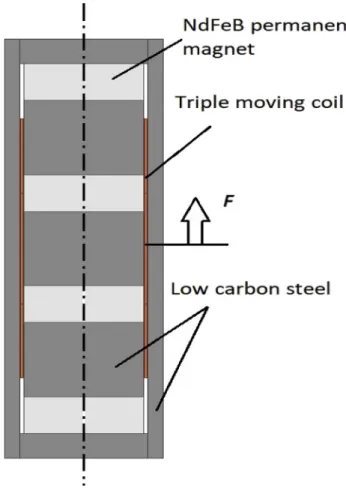
A prototype for performing high braking force to load reciprocating saws and similar power tools has been built in 2009, in the early stage of this research. This prototype was based on the construction of voice coil type linear motors, but the stator was excited by a still coil instead of permanent magnets. The structure of this prototype can be seen inFig. 1.
Theoretical basis of this prototype was evaluation of the airgap’s induction distribution and the maximum cutting force by simulation. In addition, experiences of thefirst prototype provided useful results and information for further development of this construction [1].
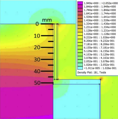
First evaluations were implemented in Finite Element Method software Finite Element Method Magnetics (FEMM, open-source simulation software for electric and magnetic problems). Figures 2 and 3 show distribution of induction in the air gap. The major advantage of this construction is a relatively high peak force production in the bottom dead center as the highest cutting force occurs in that position during the operation of jigsaws [1].
However, the spool of the moving coil is a closed aluminum cylinder. Therefore braking force depends on both the moving coil current and the induced eddy current. That is why the range of controlled braking force is limited and its range decreases by increasing the moving speed. It results that the maximum static force is only 390 N (at 2.5 A moving coil current
Pollack Periodica • An International Journal for Engineering and Information Sciences
16 (2021) 1, 1–6
DOI:
10.1556/606.2020.00153
© 2020 The Author(s)
ORIGINAL RESEARCH PAPER
pCorresponding author.
E-mail:laszlo.kazup@eiki.hu
and 3.5 A still coil current), but the dynamic peak force can be much greater due to the eddy current effect. If the exci- tation of the moving coil is opposite and its summarized magneticfield is larger than thefield of eddy currents, then the resultant force can be smaller, but the heat dissipation is quite significant in this case [2–4].
1.2. Validation of simulation by measurement
After simulation a measuring system was built to validate the results of the simulation. The main goal of this mea- surement was to check the accuracy of different model pa- rameters including material settings and boundary conditions. The main part of the measuring system was a gauss meter with thin magnetic probe. During the mea- surement the probe was moved manually from the bottom
of the air gap to its top position, and the flux density was measured in each millimeter [5]. The measuring system and the results can be seen inFigs 4 and 5. The difference be- tween simulated and measured values (average flux den- sities) is relatively small. The negative peak was occurred by the connections of the steel rings of the stator (in the model the stator is a solid steel volume, but in the real life, pro- ducing a similar shape as a solid body with ability of place windings is very difficult). These small differences mean that the material properties and the boundary conditions are correct, and they can be used in further simulations [6].
1.3. Static force simulation of the first prototype
Specification of the first prototype defines maximum braking force in measure of 500 N. However, the continuous Fig. 1.Thefirst prototype
Fig. 2.Air gap induction's distribution of thefirst prototype–simulation (rectangular plot)
current in both copper coils is maximized as well (2 A maximum moving coil current and 3.5 A maximum still coil current). Therefore, the current parameters of the force
characteristic simulation should conform to the specifica- tion. Result of the force simulation is shown inFig. 6.This simulation was solved by using the ANSYS Maxwell soft- ware pack. The maximum static force is lower than the required value (about 260 N), but the maximum dynamic force can be significantly greater than this value. Further- more, the eddy currents in the closed aluminum cylinder help to increase the maximum dynamic force [3].
2. MORE AIR GAPS, MORE POWER
2.1. Multi air-gapped design using permanent magnets
The first possible way to improve the relatively poor effi- ciency of the first prototype is applying powerful permanent magnets (NdFeB magnets). However, in this case overall construction should be modified. If the buildup includes more permanent magnets, more air gap can be realized. This solution is similar to the construction of industrial voice coil linear motors, but the internal and external steel parts are connected to each other through the air gaps only. This buildup results more difficult mechanical design. The 3-dimension model feasible design can be seen inFig. 7.
The average air gap induction is lower than the same value in the first prototype, but the maximum continuous force is 297 N, which value is greater than the same Fig. 3.Air gap induction's distribution of thefirst prototype–XY distribution
Fig. 4.The induction measurement setup
parameter of the previous construction. Furthermore, this solution can produce this force with much lower power dissipation (105 W vs. ca. 300 W) thanks to the strong permanent magnets. Due to the symmetric force charac- teristic the compensation of the moving mass can be simpler. Thanks to the non-conductive coil spool, the momentary braking force can be controlled more precisely;
the difference between the static and the dynamic force is small. By using this design, complex force characteristics can be realized within a single moving period and the peak force can be even 1,200 N (with 1/16 duty cycle max. by using composite, non-conductive spool material with high tensile Fig. 5.Induction measurement results
Fig. 6.Force characteristic of thefirst prototype
Fig. 7.Multi air gap design using permanent magnets
Fig. 8.The simulated static braking force
Fig. 9.Multi air gap construction with 4 neodymium permanent magnets
strength). The results of the force simulation can be seen in Fig. 8.
As the goal of the design is maximization of the braking force, more permanent magnets can be used to increase number of air gaps. More air gaps can handle more moving coils, so the force can be increased as well. In case of appropriate design, the force/power ratio can also be improved. The half cross-section of a possible design (simulation model) is shown inFig. 9and the results of the force simulation are shown inFig. 10. Each curve represents different current direction. Difference between the curves is occurred by the distortion effect of the magneticfield in the moving coil [7, 8].
2.2. Multi air-gapped design using exciter coil
The NdFeB permanent magnets are robust, but in case of a long-time performance test the temperature can be
continuously high; therefore design using exciting coils can be reliable in these cases [9, 10].
Figure 11shows the simulation model of a multi air-gap construction using exciter coils. The physical dimensions and the power dissipation increase, however, this con- struction is not so sensitive to long term high temperatures.
But in case of longtime operation, high power testing is essential for determination of the proper cooling. The simulated static force can be seen in Fig. 12. The dashed curve shows the result in case of negative moving coil current. The difference between the curves is occurred by the air gapfield distortion.
3. CONCLUSION
Using strong permanent magnets efficiency of the system can be maximized, and the mass can be minimized, however in this case long term high temperature conditions should be avoided. In field of industrial lifetime testing design with exciter coils seems to be a reliable solution. From the other side, major disadvantage of this solution is the weaker dy- namic behavior and the higher eddy current loss. The pre- liminary dynamic simulations show that reluctance of the magnetic circuit is smaller and inductance of the moving coil is not a linear function of the current because of the satu- rated parts of the soft steel core.
Results of simulations show that traditional “speaker- type”magnetic circuit is inefficient in this application field due to the relatively high flux leakage. Magnetic circuits including two or more magnets and three or more air-gaps can provide higher gap induction and concentratedflux of two magnetic circuits into one air gap. However mechanical construction is more complex in this case.
REFERENCES
[1] A. Varadine Szarka, “Linear magnetic break of special test re- quirements with dynamic performance,”J. Electr. Electron. Eng., vol. 3, no. 2, pp. 237–240, 2010.
Fig. 10.Force simulation results of the construction ofFig. 7
Fig. 11.Multi air gap design with exciter coil
Fig. 12.Multi air gap design with exciter coil-force simulation re- sults
[2] C. H. Chen, A. K. Higgins, and R. M. Strnat,“Effect of geometry on magnetization distortion in closed-circuit magnetic measure- ments,”J. Magnet. Magn. Mater., vol. 320, no. 9, pp. 1597–1656, 2008.
[3] D. Joneit, N. Nadler, and H. Heuer,“Correction of eddy current measurements to obtain accordance with simulation results,” NDT&E Int., vol. 62, pp. 167–171, 2014.
[4] G. Betta, L. Ferrigno, M. Laracca, P. Burrascano, M. Ricci, and G.
Silipigni, “An experimental comparison of multi-frequency and chirp excitations for eddy current testing on thin defects,”Mea- surement, vol. 63, pp. 207–220, 2015.
[5] D. Martien, “Introduction to AC susceptibility,” AC Magnetic Measurements, Application Note. USA: Quantum Design, 2001.
[6] H. E. Knoepfel, Magnetic Fields: A Comprehensive Theoretical Treatise for Practical Use.John Wiley & Sons, 2008.
[7] L. Kazup and A. Varadine Szarka, “Diagnostics of air-gap in- duction’s distortion in linear magnetic brake for dynamic appli- cations,” in XXI IMEKO World Congress on Measurement in Research and Industry, Prague, Czech Republic, Aug. 30-Sept. 4, 2015, 2015, pp. 905–908.
[8] M. Kuczmann,“Nonlinearfinite element method in magnetism,” Pollack Periodica, vol. 4, no. 2, pp. 13–24, 2009.
[9] G. Kovacs and M. Kuczmann,“Simulation of a developed magnetic flux leakage method,”Pollack Periodica, vol. 4, no. 2, pp. 45–56, 2009.
[10] N. A. Spaldin, Magnetic Materials: Fundamentals and Device Applications. Cambridge University Press, 2003.
Open Access. This is an open-access article distributed under the terms of the Creative Commons Attribution 4.0 International License (https://creativecommons.org/
licenses/by/4.0/), which permits unrestricted use, distribution, and reproduction in any medium, provided the original author and source are credited, a link to the CC License is provided, and changes–if any–are indicated. (SID_1)