MEASURING THE MAGNETIC DIPOLE OF A SATELLITE
C. Usiskin and R. Wilkes Astro-Electronics Division RADIO CORPORATION OF AMERICA
Princeton, New Jersey
Abstract
The interaction between a satellite's magnetic dipole and the earth's magnetic field will cause applied torques on the satellite.
This paper describes an experiment which determined the magnetic dipole of TIROS Π, a spin-stabilized meteorological satellite. Methods were developed in which small magnetic dipoles [ l amp - ( meter )2 ] can be measured while the satellite is being operated in various modes during both nighttime and daytime conditions.
Introduction
A recent analysis (1) of the spin-axis motion of TIROS I * determined that the cause of this motion was due to combined magnetic and gravitational torques. Of these, the magnetic torque caused the largest long-term movement of the spin axis. This motion suggested the possibility of controlling the orientation of a satellite by using the extremely small magnetic forces of the interaction of magnetic dipoles within the satellite with the earth's magnetic field. The satellite's magnetic dipoles were caused by either magnetic material or direct currents flowing in closed paths. From the motion of the spin axis of TIROS I, it was deduced that the satellite had a net dipole moment equivalent to a current of 0. 9 ampere flowing in a plane perpendicular to the spin axis and enclosing an area of one meter squared. Ten pounds of ferromagnetic material with a residual magnetism of 25 gauss also produce a dipole of o. 9 amp-turn-m2. Hence, it was possi
ble that the magnetic dipole of TIROS I could have been due either to
* TIROS I was a spin-stabilized meteorological satellite which was injected into orbit on April 1, 1960, at iih 52m GMT.
current loops or to magnetic material. Although the maximum torque caused by a dipole moment of 0. 9 amp-turn-m2 was only 1.6 χ 10""5 ft-lb, this torque caused the spin axis to precess at the rate of about 4° per day. For this reason it was decided that the dipole moment would be reduced for TIROS Π** and that a controllable dipole moment would be produced by a coil of wires about the spin axis.
Before one can reduce the magnetic dipole of a completed satellite, methods of measuring its strength and direction must be developed. It is the purpose of this paper to describe the experiment by which the magnetic dipole of TIROS II was measured. The torque produced by dipoles of the order of 1 amp-turn-m2 is entirely too small to permit a force measurement. Field mapping also is not practical since the field produced by the satellite is small compared to the earth's field at distances of over one meter from the satellite.
This makes a 3-dimensional determination of the satellite field very difficult and time consuming. A third method, and the one used, was to spin the satellite about an axis perpendicular to the spin axis inside a coil of wires. The voltage induced in the outside coil is a direct measure of the dipole of the satellite perpendicular to the axis that the satellite is spun about in the test. Since the total dipole moment along the spin axis is made up of many dipoles in different locations in the satellite, the measuring coil must be built in such a way to ensure that all of these dipoles contribute equally to the induced volt
age in the coil. This can only be done if the coil produces a uniform field throughout the region of the satellite. A specially wound spher
ical coil, described later in the text, accomplished this. A second spherical coil was used to cancel out the earth's field so that induced eddy current and induced dipole moment noise would be kept to a minimum. To simulate daytime operation a large number of photo- floods were attached to the structure and arranged to approximate the satellite oriented with its spin axis at about 30° angle to the solar flux. When the lights were turned on, the total solar cell output was within 5% of the calculated output when in direct sunlight.
Once the satellite dipole moment was established, a small per
manent magnet was added to the satellite to cancel out the measured dipole. The satellite was then retested in all its modes with the mag
net added to ensure that the orbit average dipole was close to zero.
** This work on the TIROS II Satellite is sponsored by the National Aeronautics and Space Administration on Contract No. NAS 5-478.
In o r d e r to control the net dipole while the satellite is in orbit, a coil of w i r e w a s wound around the outside of the solar cell structure. The current through this coil could be controlled f r o m the ground to p r o duce eleven different values of the dipole along the spin axis ranging in value f r o m +3 amp per m2 to - 3 amp per m2. The effectiveness of this coil was also tested.
Theoretical Considerations
The magnetic field within a spinning, uniformly-charged s p h e r ical shell is constant in magnitude and parallel to the spin axis of the sphere. Similarly, a sphere with an axial surface current density proportional to the cosine of the latitude will also have a uniform in
terior magnetic field ( 2 ) . This type of surface current density can be approximated by winding a coil on the outside of a sphere with the density of windings just equal to the cosine of the latitude. The magnetic field intensity within a sphere of radius R with current i through an axial coil of Ν turns is
If the axis of the sphere is parallel to the earth's magnetic field it is possible to cancel out the magnetic field within the sphere by adjusting the current through the coil.
A spinning dipole within the sphere will cause a voltage to be induced in the outside spherical coil. In order to calculate the magni
tude of the voltage induced by the spinning dipole we first find the volt
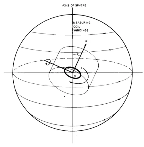
age induced in a circular loop of w i r e of a r e a A at an angle Θ to the axis of the measuring coils due to changes in the current measuring coil ( s e e F i g . 1 ) .
The magnetic flux through the loop is
Φ = / h . H d A = A H c o s θ Hence, the induced voltage inside the loop is
άΦ _ Αοο8 0 Ν μο Ε = d t
3 R
Thus, the mutual inductance between the sphere windings and the loop is
Α ο ο β 0 Ν μο
L1 2 = L2 1 = 3 R
A X I S OF S P H E R E
Figure i. Basic Geometry of the Experiment.
This figure shows a loop of current-carrying wire of area A inside of a large spherical measuring coil. The normal to the enclosed area A makes an angle θ = cot with the axis of the measuring coil.
F r o m this expression we can deduce the voltage induced in the outside sphere windings by a spinning dipole moment of strength I A . If we now consider the above ring with a current of land the loop spin
ning about an axis perpendicular to the axis of the sphere at a rate ω, 0 = ωί then the induced voltage in the outside coil will b e :
d L2 iI Ι Α Ν ω μ0
E d = - d f - = - 8 R - Î B , n w t ( 2 )
This expression shows that the measured voltage has frequency ω and the magnitude is proportional to the dipole strength ( IA ) and the speed of rotation. The voltage induced by a satellite spun at a known speed ω inside the spherical coil will determine the satellite's dipole moment.
A second voltage will be induced in the measuring coils due to eddy currents in the satellite and metal yoke which spins the satellite.
These eddy currents a r e caused by the earth's magnetic field's induc
ing voltages in closed metal loops. Most of the current loops come from the metal yoke which holds the satellite and is part of the e x p e r i mental equipment. Although the induced eddy currents caused by the satellite's spin in space do create a torque, the effect of this torque is small compared to the noninduced dipole torque. This second-harmonic, induced voltage will be superimposed upon the voltage caused by the dipole moment and, hence, constitutes noise. In order to estimate the magnitude of the second harmonic, we will consider the satellite and yoke as being replaced by a single metal ring of a r e a A and electrical resistance R e .
The eddy current induced in the ring is 1 άΦ ΗθΑ ω
I' = — — - = cos cot cos φ
R dt Rc
e ve
where He = earth's magnetic field
φ = angle between the axis of rotation and the earth's magnetic field
The induced voltage due to eddy current is d I ' L2 1 μ0Α2ω2Ν ΗΘ
En = — — = j j ^ - g - cos(?sin2ajt ( 3 ) One interesting feature of this equation is that the frequency of
induced voltage is twice that of the voltage induced by the dipole. A l s o , the magnitude is proportional to ω2, which means that a better signal- to-noise level can be obtained by decreasing the speed of rotation.
Evaluation of Eq. (3) for some typical values of the parameters shows that due to the large holding yoke the induced eddy current sig
nal could be larger than the dipole signal. For this reason, it is necessary to perform the experiment in a field-free space. In order to approximate this condition a second coil of wires, identical to the first, was wound on the sphere and the sphere's axis was lined up with the theoretical earth's field. By passing a current through the second outside coil, a field which is equal and opposite to the earth's field can be produced inside the sphere. Thus, within the sphere no magnetic field should exist, hence, no eddy current signal.
Experimental Apparatus
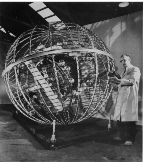
The experimental apparatus, shown in Figure 2, consists of a gimballed mount with three degrees of freedom which can accept test pieces as large as 40 χ 50 χ 50 inches. This mount is cantilevered so that its center is coincident with a 100-inch sphere which circum
scribes the entire amount. The mount is driven only along one axis, with the other two being locked at some desired position at all times.
The desired effect is to be able to spin the test body about any arbi
trary axis with a continuously variable speed from zero to 120 rpm.
It is desirable to avoid ferromagnetic materials in the struc
ture of the apparatus and, as much as possible, avoid the close prox
imity of ferromagnetic materials such as the roof or walls of a steel- framed building. The first requirement is imposed because the r e sidual magnetism in a ferromagnetic structure would produce a very large contribution to the measured signal. This is inherently unde
sirable from a measurements standpoint and is also likely to be a constantly changing quantity due to percussions, cyclical stresses and temperature changes. The latter requirement regarding such things as the covering building is imposed because the presence of ferromagnetic material alters the local lines of force of the earth's magnetic field. This alteration affects the strength of the field from point to point as well as its direction making the cancellation of the earth's field within the sphere impossible.
The inclination of the magnetic field at the latitude of Prince
ton is approximately 72° measured from the horizontal. The windings on the sphere necessary to produce a field in this direction must make an angle of 18° with the vertical. The great circle of the sphere with this inclination is chosen as the separation plane to facilitate sphere removal and allow access to the gimbal mount. The sphere is almost entirely constructed with rolled aluminum extrusions, the only excep
tions being the polar caps, which are machined disks. Construction
Figure 2. Magnetic Test Apparatus.
is similar to an umbrella as shown in Figure 2. The meridian ribs are channel members 3/4-inch square with i/8-inch wall thickness.
The equatorial mating members a r e 2-inch angle sections i/8-inch thick. The resultant sphere weighs less than 100 pounds and, with the addition of 80 pounds of N o . 26 copper w i r e , supports its own weight with negligible deflection when resting on one polar cap.
The gimbal structure is cantilevered primarily to achieve a high degree of accessibility for sphere removal and test body i n s e r tion. The additional structure required for a cantilever design is not unreasonable in view of the anticipated weight of the test body. Stress considerations a r e quite negligible compared to the stiffness r e q u i r e ments imposed b y the rotational speed. This requires that the lowest mode of vibration of the rotating structure be higher than the rotation
al frequency. F o r a lightly damped structure such as this, the struc
tural natural frequency was designed to be twice the maximum r o t a tional frequency. Looking at the gimbal structure with test body in place as a distributed spring mass system yields a combination of s e r i e s , parallel, and s e r i e s - p a r a l l e l connections whose loading varies with the orientation of the structure to gravity. Taking the worst orientation and designing each element of the structure to have the same stiffness when reflected at the gimbal centers yields the design of Figure 2. Intersecting tubes w e r e chosen for the yoke so that alignment comes f r o m the sliding fit of tubes into machined holes rather that welding alone. The gimbal is a 4-inch aluminum H section with mitered welded c o r n e r s . The inner gimbal c a r r i e s all the light
ing fixtures arranged in three groups. A flat plate, 40 inches in d i a meter, mounting fifty-two i50-watt bulbs provides near-uniform illu
mination for the top section of TIROS. Two identical rings mounting eighteen 300-watt bulbs each a r e provided on either side of TIROS to illuminate its sides. Only half of these lights occupying 180° of a r c are illuminated at any one time. This grouping of lights is rotated electrically at 12 r p m to simulate the sun's illumination on the sides of a rotating satellite. This is accomplished by a motor-driven bank of 18 cam-operated micros witches.
Power for these lights as well as other control w i r e s pass through heavy-duty silver slip rings on the main support shaft. The gimbal drive system is by belt f r o m a 1/3-hp variable speed d-c motor.
Instrumentation
The signal that is measured has a frequency equal to the f r e quency of rotation of the satellite within the measuring coils, about
one cycle per second. The magnitude of the signal is usually under 5 millivolts peak-to-peak. The 60-cycle noise picked up by the coil was many times greater than the signal, as was the 2-cycle signal due to induced eddy currents. In order to reduce all unwanted signals, a Krohn Hite, U l t r a - L o w Frequency B a n d - P a s s F i l t e r , Model 330M, was used. The upper and lower cut-off frequencies w e r e set at the r o t a tional frequency of the machine, thus, producing a n a r r o w frequency- response acceptance band that is about 2 db down at the signal f r e quency and drops at the rate of 24 db per octave on either side. The filtered signal was recorded with a Type 532 oscilloscope with a l o w - frequency preamplifier, Type 53/54 E . This preamplifier also had a filter system which was set at 50 cycles at the high-frequency and 0.06 cycle at the low-frequency end. The oscilloscope was adjusted to sweep on receiving a signal f r o m the rotating satellite. A polaroid oscilloscope camera was used to r e c o r d the resulting sweep.
Experimental Procedure Calibration
Before the satellite was tested, the response of the measuring system and the magnetic dipole of the rotating experimental structure had to be determined. This was accomplished with the aid of two c a l ibration coils which w e r e mounted on the spinning part of the équipe
ment. The axis of one of the coils was parallel to the spin axis of the satellite when it is mounted in the test equipment, while the other coil axis was perpendicular to the axis. Current was supplied to these coils f r o m external power supplies through slip r i n g s .
The rotating structure without the satellite was spun at the test frequency, one cycle per second. With no current through either c a l ibrating coil or through the cancellation coil the pickup coil registered a l a r g e two-cycle signal, and a small one-cycle signal. The Krohn Hite filter was set to allow only one cycle signal, and filtered outmost of the signals of higher frequency than two cycles. The second-har
monic signal was reduced by cancelling out the field inside the sphere.
This w a s done by passing a current through the cancellation sphere and observing the induced signal. In this w a y , the minimum eddy current signal w a s achieved.
Once the second harmonic was reduced to a minimum, the two calibration coils w e r e used to determine the net magnetic dipole of the rotating structure and to determine the sensitivity of the testing equipment. The f o r m e r was accomplished by adjusting the current through the two coils until the first harmonic was reduced to zero.
When this was done, the dipole created by the calibration coils was just equal and opposite to that of the rotating machine.
In order to test the response of the measuring equipment, the current through the calibration coil at right angles to the spin axis is kept constant while the current through the calibration coil is varied.
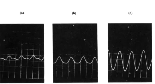
The total area of the latter coil is 1.46 m2. Figure 3 ( a , b, and c) show the type of pictures that were obtained for calibration purposes.
From pictures like these, it was determined that a dipole of 1-amp - m2 strength produces a signal of 2. 04 millivolts peak-to-peak or, in other words, the sensitivity is0,492amp-(m)2/mv. This value was checked before each experimental run with the satellite mounted. The sensitivity was found to remain constant throughout the tests.
Tests
The satellite was mounted in the test equipment and rotated at a speed of i r. p. s. The filter was set for a narrow band-pass at one cycle and the calibration coils were connected in the same way as when calibrating. The cancellation-coil current was adjusted to give minimum second-harmonic noise. The oscilloscope was set to sweep on a signal taken off the shaft of the rotating structure so that the phase of the induced voltage, relative to the rotation of the satellite, could be determined.
After the calibration was checked, the net dipole moment of the satellite without power was determined in two ways. The first was to simply take a picture of the oscilloscope trace and use the calibration and phase information to compute the component of the magnetic dipole along the spin axis and perpendicular to it. The second method was to cancel out the dipole by passing current through the two calibration coils. Usually both methods were used for the satellite with no power and the satellite in the standby power mode at night. Since only the dipole along the spin axis was of interest, the calibration coil at right angles to the spin axis was left with a current flowing which cancelled out the perpendicular dipole moment of the satellite in the nighttime standby mode. In order to test the daytime dipole moment, the lights which simulate the sun were turned on, and the resulting signal was recorded with an oscilloscope camera.
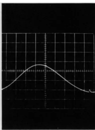
Figure 4 shows the difference between the nighttime dipole and the daytime dipole of a TIROS II satellite. It is noted that both a dipole parallel to and one perpendicular to the spin axis are induced by the daytime current loops. Since the time was limited during which the satellite could be kept running without recharging, no attempt to pro
duce a cancellation dipole with the calibration coils was made. Other modes which were tested are:
(a) (c)
Figure 3. Calibration Oscilloscope Pictures.
2 (a) With a calibrating dipole of +0. 146 a m p - m ) (b) With a calibrating dipole of -0. 292 a m p - m (c) With a calibrating dipole of -0. 89 m^
Note the presence of a small second harmonic noise signal on picture (a). The oscilloscope was set to sweep at 2 c m / s e c and a sensitivity of 0. 5 m v / c m .
(a) (b)
Figure 4. Calibration Oscilloscope Pictures.
These oscilloscope traces show the signal from a satellite in standby mode at (a) night and (b) day. F o r this satellite the day-night effect was quite extreme. The sweep speed was 0. 1 cm per sec. Note the trigger signal at the end of each sweep which provided phase information.
( i ) Direct picture taking and transmitting with alternate cameras
( 2 ) Remote picture taking and storage with alternate cameras ( 3 ) Playback and transmit of the stored information of each
camera during day and night conditions.
Two complete series of tests were necessary for each satellite.
After the first series of tests, a small magnet, which has the same strength dipole as the orbit average satellite dipole, was placed on the satellite in such a way as to cancel out the satellite* s dipole. The satellite was then retested with the magnet.
Results
Tests were run on three different TIROS Π vehicles. It was quickly determined that all three had magnetic dipole moments of the same order of magnitude as was calculated for TIROS I . When these vehicles were tested with the payload-power off, a large fraction of their average magnetic dipole remained. This showed that magnetic material caused an appreciable effect in the motion of TIROS I spin axis. Although a strong effort was made in the TIROS I program to eliminate all magnetic material there was still about 10 pounds of ferromagnetic material in the satellite.
The most important mode of operation in terms of contributing to the average dipole moment is the standby mode. For nighttime operation it was determined that the magnetic dipole caused by current loops was small ( under 0.10 amp-m2), while for daytime operation it was as large as 0.35 amp-m2, for one satellite. This day-night varia
tion is due to the battery charging current from the solar cells. Other operational modes differed from the standby mode by as much as 60%.
Although these other modes, such as remote picture taking, did not greatly influence the average dipole moment under normal operating conditions, it is possible that an unexpected method of operation might cause some mode other than a standby to become important. For the TIROS II vehicle tested that was launched on November 23, i960, the uncompensated standby dipole was 0.97 amp-turn-m2 during nighttime and i. 39 during daytime. With a small compensating magnet, these values are reduced to -0.31 and + 0,10 amp-turn-m2 respectively.
During the tests, the magnetic control coil was calibrated.
The tests showed that the presence of the small amount of iron in the satellite did not measurably change the effectiveness of the coil.
Thus, the magnetic dipole of the control coil was simply μ0Ι A.
Acknowledgement
The authors wish to thank D r . W. P. Manger for the many helpful suggestions and ideas he contributed.
References
1. Bandeen, W. , and W . P. Manger, "Angular Motion of the Spin Axis of the TIROS I Meteorological Satellite Due to Magnetic and Gravitational Torques, " J. of Geophys.
Research, September I960.
2. Smythe, William, Static and Dynamic Electricity, Second Edition, M c G r a w - H i l l Book Co. , pp. 274, 1950.