OPERÁCIÓS RENDSZEREK ELMÉLETE V. VISEGRÁDI TÉLI ISKOLA
Tanulmányok 100/1979
Szerkesztőbizottság ï
GERTLER JÁNOS 3 (felelős szerkesztő) DEMETROVICS JÁNOS (titkár)
ARATÓ MÁTYÁS, BACH IVÁN, GEHÊR ISTVÁNt GERGELY JÓZSEF3 KERESZTÊLY SÁNDOR3 KNUTH ELŐD,
KRÁMLI ANDRÁS, PRÉKOPA ANDRÁS
Felelős kiadó:
ДЯ VÁMOS TIBOR
MTA Számítástechnikai és Automatizálási Kutató Intézete MTA Számítástudományi Bizottsága
Konferencia szervező bizottsága:
ARATÓ MÁTYÁS (elnök) KNUTH ELŐD (titkár)
VARGA LÁSZLÓ
ISBN 963 311 097 1 ISSN 0324-2951
79-1835 Tempó Sokszorosító - 300 pld.
F.v.: Vojvoda György
A konferenciát a "Számítástechnika tudományos kérdései" c.
többoldalú akadémia együttműködés keretében rendeztük.
Конференция была проведена в рамках многостороннего сотрудничества академий
социалистических стран по проблеме
"Научные вопросы вычислительной техники"
Conference was held in the frame of the multilateral cooperation of the academics of sciences of the socialist countries on
Computer Sciences.
4
TARTALOMJEGYZÉK
Jose Busta, Serge Miranda:
Interference problem in distributéd computing ... ^ Y. Bashin, I. Gorelik, H. Pranevitshius:
Computer network evoluation by program simulation .... 23 Bernus Péter:
An intel 8080 based multitask supervisor ... . 45 Georges Gardarin:
Problems and solutions for updating multiple and
distributed copies of data ... 65 A. Krámli, P. Lukács:
The asymptotic distribution of the cost function of an
adaptive system recovery procedure ... 91 A. Wolisz, J. Izydorczyk:
Oueueina systems with waiting time dependent ... ^03 service times
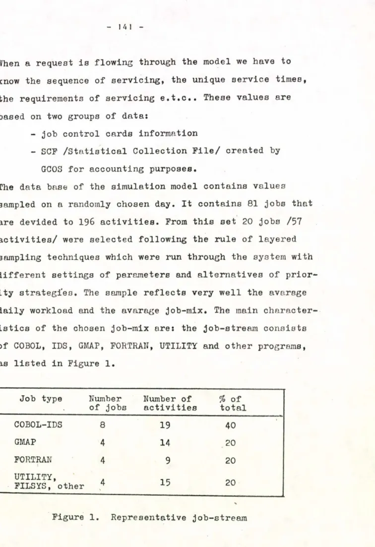
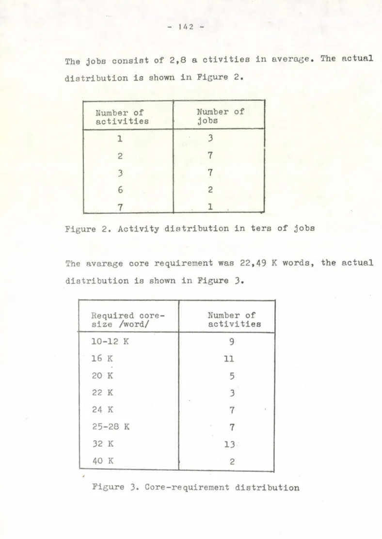
S. Zárda, A. Nagy:
Simscript simulation model for computer system
evaluation ... 137 Dávid Gábor:
Problemsolving strategies ... 155 Michel Scholl:
Dynamic hash-coding: New schemes for structuring data the volume of which is allowed to grow and shrink bv
large factors ... 159 G. Bergholz:
Behaviour models of computer systems ... 199 D. Ambrózy, A. Szabó, K. Tarnay:
A program package architecture for computer network
measurement 219
An approach to performance evaluation and menaqement of a time-sharing computer installation by analytical
methods ... AP 17' T. Muehleisen, W. Wietrzych:
A free memory organization for an operating system
of a front-end processor ... 253 A. Iványi, I. Kálmán:
Generalized bin-packing problems in processor
scheduling ... 271 Kovács Győző, Németi Tibor:
Evaluation of a Time-sharing Computer System ...283 A. Iványi, Z. Pókos:
The effect of page size on the speed ... 301 Jan Rudolf Just:
An algebraic model of the distributed computer system 3Il C. Glowacki:
A Scheme for Conceiving Methods to Control the Degree of Multiprogramming for Virtual Memory Computer
Systems ... 325 Dávid Gábor:
Architecture language ...341 Gábor Hrotkó, Gábor Simor:
A protection mechanism for modular systems ... 351 Wyn L. Price:
Simulation studies at NPL of flow control and
routine in packet-switched networks ... 375
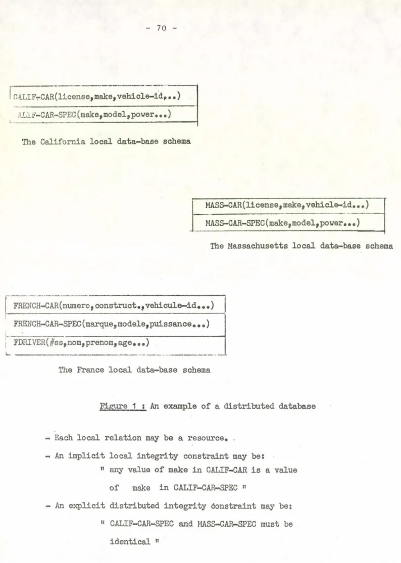
INTRODUCTION
In local DBMS one of the major abjectives at the imple
mentation level was to avoid data physical redundancy.
*
This entailed the requirement to share data among users having different needs and therefore to control update concurren
cy which we call "external integrity" ; it is important to note that every proposed solution, included in the Univac's DBTG-like DBMS (DMS 1 100) where the initial "monitoring mechanism" was gi
ven up, is based on a LOCKING MECHANISM (low or high level).
From locking,stems the potentiality of deadlock (locking is one of the five necessary conditions for deadlock). The major purpose of this locking mechanism is to maintain data base consistency.
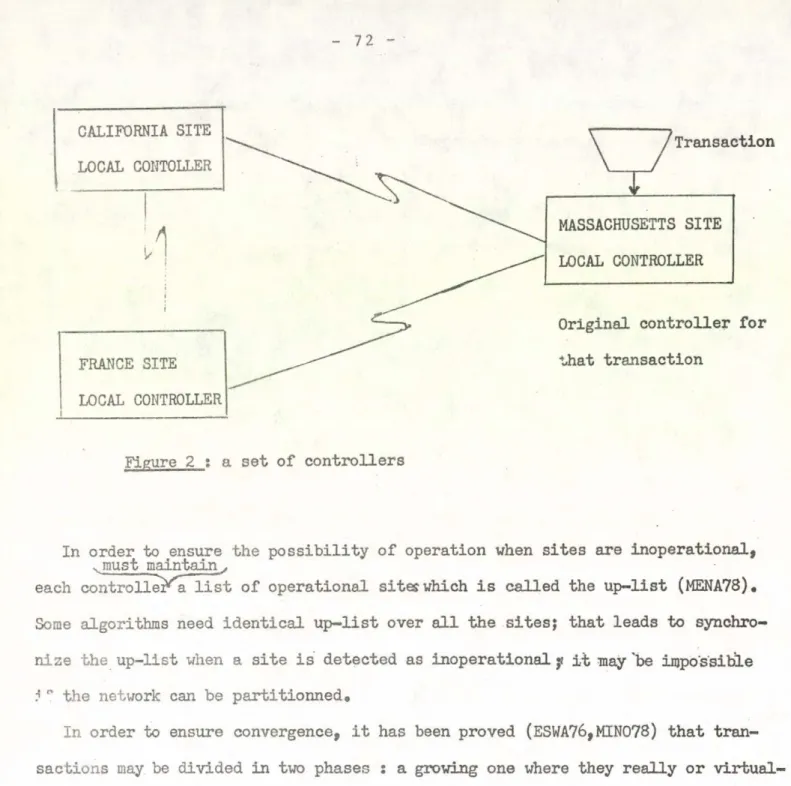
In distributed data bases, physical redundancy among remote parts of the scattered data was re-introduced, mainly for availability and reliability reasons. This redundancy can be
"identity", "extension" or "restriction" of a given entity.
Mutual consistency of these "duplicated" entities must be main
tained. This will be performed via an external integrity mecha
nism which will control the concurrent access to the data.
We address <in (1) the generalization of this issue to
"partitionned data bases" where different data modules are loca
ted throughout the network (without being necessarily semanticà- lly tied).
We defined a global locking mechanism to tackle the ex
ternal integrity problem.
External integrity is only one aspect of the interferen
ce problem ; the second is concerned with UPDATE PROPAGATION through the different functional levels (external, conceptual, access-path, encoding, physical device) of a DBMS (local or distributed).
91
Computing Center University of Santiago de Compostela, Spain
** Cerise-University of Toulouse I, France
8
This problem was only partially solved :
- SYSTEM-R defined simple rules between the external and con
ceptual levels like the "rectangular and "uniqueness" one ; - INGRES defined simple mapping algorithms of the same type ; - IBM-Los Angeles system included "reflection rules "Mithin
the definition of external entities.
Only PAOLINI in the university of MILANO tried a uniform and ri
gorous approach based on abstract data types to deal with this problem.
In the remainder of this paper we will present our solution and modélisation to the external integrity issues for distributed duplicated entities. We will focus our attention on a fail-safe
computer network.
MAJOR FEATURES OF OUR ALGORITHM
The significant characteristics of our synchronization protocol are :
- strong consistency ;
at a given point of time, every open copy is in the same consis
tent state (even in case of any failure in the distributed system).
- global locking ;
our protocol implements mutual exclusion this requires the defi
nition of a coordination protocol among remote controllers. We choose a preclaiming strategy (which appears to be the only pre
vention solution possible in a distributed environment) to deal with deadlock ; as a consequence our protocol will encompass two_
steps_ o_f synchronization.
General purpose network oriented ;
its control is decentralized. There is no privileged controller a priori ; there is a master-site dele rmination during the first step based on a priority system (including parameters like TIME- STAMß REJECTION number, less-priority transaction list,...).
Every transaction will be processed after an indefinite but finite time. Our protocol must be efficient (transmission overhead in the order of 5 (n-1 ) messages with n, number of copies,but with a res
ponse time independant of n due to parallel transmission/processing) and robust. This requires that every global operation be t ^ o - P M S E . At last our protocol is speed independent by the integration of acknowledgement messages.
APPEAL OF DISTRIBUTED CONTROL
Centralized control is attractive due to the general simplicity of the corresponding algorithm (minimal message transmission, simplification of the conflict resolution, possibility to use deadlock detection al
gorithms,...) and turns to be adequate for star-like network structures or centralized applications.
However such a solution н х х е н н^г я$^х и1х иpJsíxIhÍIm 6 in case of central site failure or isolation and dd.es not meet the objectives of a general purpose computer network (i.e ARPANET, CYCLADES, EIN,...) like modular growth, crash confinement, reliability, local autonomy and load sharing.
For these above requirements to be true it is necessary to provide all the processes with equal poxer. Therefore we discarded the centralized control approach and define a protocol where all controllers are initial
ly equal. This distributed control makes use of a priority system which will be used for deadlock prevention and master site determination.
A protocol using a distributed control can be made extremely robust. The final advantage of the distributed approach is that the proof of correct
ness of such an algorithm (identical in each controller) is easier to conn duct.
Our protocol is "message- driven" } the activity of each autonomous con
troller will be coordinated by synchronization messages and a sequence of actions will occur as a consequence of the reception of a dedicate message or a group of messages.
There are two steps of synchronization corresponding to :
- the election of a "master controller" and the resolution of conflicts which can occur among concurrent transactions.
- the global locking-update-unlocking is then performed by the master controlhrwith the other controllers called "slaves” .
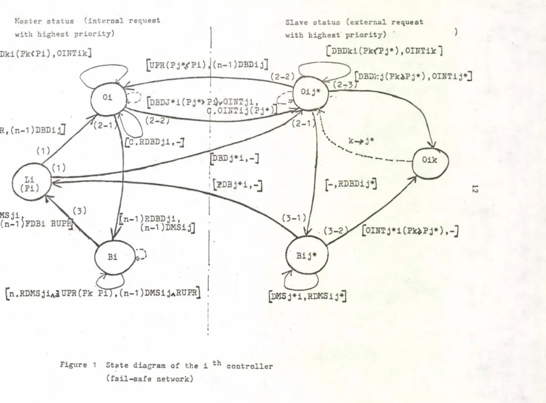
STATE DIAGRAM
An algorithm is best staded via some abstract means which is accurate and implementation independent .
Each message causes a transition among states of locks (global and local).
This is a reason why we use an automata-like formalism to represent our algorithm.
We have 3 different resource states (or lock states) t
- free (F) I there is no global synchronization process in progress. Any update request can be ini- ' tiated.
- occupied (0) : there is a global synchronization process in progress but the master controller, elec
ted during the first step of synchronization con still switch. This state corresponds to the protected modeu and an update request can still be considered.
- blocked up (B) t there is a global synchronization process in progress and the resource (global or local) is blocked up for a given master controller. This state corresponds to an exclusive mode.
X = }.A.,DBD, RDBD, D MS, RDMS, FDB, OINT, UPR, RUPßj
Q * [ Fi, Oi, Oij, Bi, BijJ
F = qo s= J_Fi^
S : transition function depicted in figure 1
Notation of figure 1
Xij : lock state with X c {.0,B^ means that the controller i is in the state X for the controller j
---3» t transition arrow between lock states - labelled with transition-id
- numbered with the order it appears in the protocol
transition-id = ^received message (s)^ significant parameter), transmitted messa gefe)J
q/. Aij : A-type message (s) from controller i to controller j (received or transmitted)
A can be of the following type s
UPR update request sent by the external user and its acknowledgment RUPR
DBD t demand for distant blocking and its ACK , RDBD
DMS : demand for synchronized update and its ACK, RDMS OINT : order of interrupt
C s message counter c [ l , n - 1 £
Figure 1 State diagram of the i ^ controller (fail-safe network)
Locking in a distributed data base cannot be reduced only h> :
- a data structure (like the "rectangular view" defined in System-R...) or
- a coordination protocol (like in duplicated file systems...) which would lead to a sub-specification. Hence the appeal of abstract data types (ADT) which allow to consider locking both as a data structure and as a set of operators defined on it.
Since the data structures involved in locking a DB are complex we will choose the algebraic approach (instead of the propositional approach more suitable to simple structures) to describe the different ADTs attached to each func
tional level of a distributed DBMS (at least, five levels have been iden
tified (1) ).
Therefore, the synchronization system will be seen as a set of ADTs depicted as homomorphic £ -algebras.
We will have a twofold mapping to define for the operators and the data- structures
(Data base, UPR)
(DBk, UPRk)
OP
OPi >
(Data base, answer)
In the particular case w e consider (duplicated file system), locking is reduced to the second type of locking, taken into account in the coordina
tion protocol between the global level and the local level (concerning each local copy).
We depict in figure 2 and 3 both ADTs atta ched to the previously defined protocol. We use the syntax of OBJ which is an object oriented language defined in UCLA (6).
We use also the fact that a finite date automata (fig. 1) represents a par
ticular class of 2 -algebra and we will consider the lock states (global and local levels) as the carriers of the corresponding algebra.
To each of these levels, we associate tw o ADTs, SYNCG and SYNCL which are 2 -algebras defined by the 5-uple
< s tx . s Д » к > where - S is the set of sorts
- £• is the set of operators defined on the sorts - 2 is the set of error operators
- % is the set of equations of the T operators - К is the set of equations of the д operators
Notation for the figures 2 and 3
foP1, OP2] indicates a running parallelism between the operators 0P1 and л 0P2
«(. OPi expresses that the operator i will be executed in parallel on remote controllers
ATT(UPR(PK)) there is scheduler call and the request with parameter P * is delayed. This action is external to the protocol
KAJL : update operator of the local file (external to the protocol).
OBJECT SYNCG
SORTS E,D
OPS ODBD B,D — > E, E
ORDBD E,D — -> E ODMS E — — » E f E' ORDMS E,D — > E,E' OFDBD E — ^ E OINT E - > в OUPR E,D -- >
e,
e vID E _ > E ERROR-OPS
ERR1 ->
e,
dERR2 -> B fD
ERR3 > B,D
ERR4 > в
ERR5 > E
ERRé >
e,
dERR7 >E ,D
ERR8 > E
ERR 9 > E
ERR10 > E
ERR1 1 > E VARS
Oi : E , Bi : E , Li : E Л = C : D , Pi : D , - : D
E'
С 6 [1 ,n-lj
ги& i « £1 ,n]
Pie[l,n]
16 SPECS
OUPR (Li
,Pk)
=ГODBD (Li,-), (n
-1)ODBD' (A'Pk)J
OUPR (Oi,Pk)
=IF Pk<Pi THEN
V "ATT (UPR (Pk))
,ID(Oi)J ELSE ’ATT (UPR (Pi)),ID(Ok)]
OUPR
(Bi
,Pk
) =[ATT (UPR (Pk)), ID
(Bi)]ODBD (Li,-)
=(o í,jQODBD (Oi,Pk)
=IF Pk 4 Pi THEN ‘iD (Oi), OINT (Ok)J ELSE ID'(Oik,Pk)
,ORDBD (Ok
+
С
XOJNT
'(Bji,Pk)]
ORDBD (Oi, c
)=IF C
=n-1 THEN ODMS (Bi) ELSE ID (Oi) ODMS (Bi)
-= [lD (Bi)
+MAJL
,(n-1) ODMS' (Bji)J ORDMS (Bi
,c )
±IF C
=n-1 THEN[OFDBD (Bi)., (n-1) OFDBD
+ o r u p r]
ELSE ID (Bi) OFDBD (Bi)
=Li
OINT (Oi)
=OivOij ID
(•Л.) = Л.ERROR-SPECS
ERR1
=ODBD (Bi,-) ERR2
=ORDBD (Li,-) ERR3
=ORDBD (Bi,-) ERR4
=ODMS (Li) ERR5
=ODMS (Oi) Е1Ш6
=ORDMS (Li,-) ERR7
=ORDMS (Oi,-) ERRO
=OFDBD (Li) ERR 9
=OFDBD (Qi) ERR1 0
= OINT (Li)ERR1 1
= OINT (Bi)TCE JBO Figure 2 Abstract, data type, C.YNCG (global level) written in OBJ
( "0 The local controller waits for (n-1) RDBD ; the master switch, located on the same site, is transparent to the remote controllers.
0P3
•ERROR
VARS
SPECS
ODBD» i E ’ ,D ' --- > E' ,E ORDBD' ; E ’ --- > E»
ODMS * i E ’ -- -* E'
OPDBD» : E' --- > E' ORDM3' : E' --- > E ’ OINT' s E ' ,D' --- > E»
OU PR : E ' , D ' --- > E ’ ,E ID* s E* -- --- > E»
ERR 1 -- > E' ,D ' ER R 2 -- > E ’
ERR 3 -- > E'
ERR 4 -- > E ’
ERR 5 --> E ’
ERR 6 -- > E'
ERR 7
---E ’
ERR 8 -- У E' ,D '
ER R 9 -- > E* ,D ’
Oij : E , Bij : E' , Lj
•
• D , Pi s D»
A* = OijvLj
O D B D ’ (Lj,Pi) = ODBD' (Oji,Pk)=
O R D B D ' (Oji) = ODMS ' (Bji) = O R D M S ' (Bji) = O F D B D ' (Bji) = OINT' (0ji,-)=
OU PR ' (Oji,Pj)=
OU PR ’ (Bji,-) = ID» (Oji,Pk) =
[lD'(Lj,Pi),ORDBD (Oi,-)]
IP Pk ^ Pi THEN [ID ' (Oji,Pi) ,OINT(Ok)]
ELSE [iD* (Oji,Fk) , OINT (Oi)-'r ORDBD(Ok,- Bji
[lD'(Bji,-),MAJb]
[lD'(Bji,-),ORDMS (Bi,-)]
LJ
OjkIF P H Pi THEN [iD* (Oji,Pi) , ATT(UPR(Pi) ELSE [lD( O j
) ,(n -1
)ODBD’ (A
fPk)][ATT(UFR (-)),ID' (Bji,-)]
Ojk
- 18
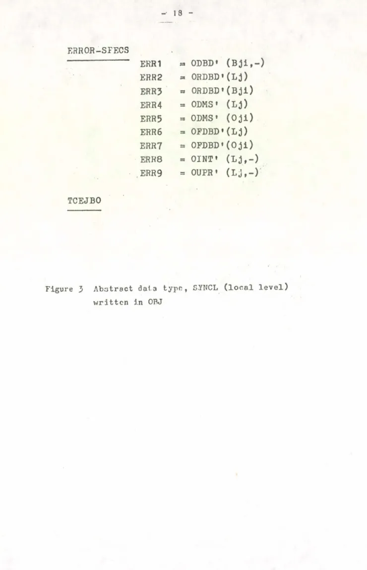
ERROR-SFECS
EKH1 « ODBD» (Bji,-) ER R 2 = ORDBD' (Lj ) ERR? =* ORDBD »(Bji) ERR4 = ODMS• (Lj) ERR5
ERR 6
= ODMS* (Oji)
= OPDBD'(Lj) ERR7 = OPDBD'(Oji) ERR8 =
OINT» ( Lj ,
- )ERR 9 = OUPR » (Lj,-)
T C E J B O
Figure 3 Abstract data type, 5.YNCL (local level) written in OBJ
(the latter corresponds to the fact that the local resource can be in the blocked state while the global resource is still in the occupied state (waiting for all acknowledgements)).
As a matter of fact each of the following diagram» commutes s.
У si 6 5 --- s*i € S'
V (Ts « I _______________ \ ^ <J»s = < r £ e I'
<r
1 Ye k s
->
i
s ' i ---ű --- >
i в* i
The demonstration is straight forward.
If we choose the £ -algebra SYNCL as the reference algebra"(homomorphic to the implementation algebra) therefore the global -algebra SYNCG will be implementation correct.
Én order t6 be rigorous, we will have to show that SYNCL is an "initial algebra" (6) (specification correct) and that there exists an isomorphism between SYNCL and SYNCG in order to make SYNCG "initial".
20 PERFORMANCE COMPARISON
Response time Transmission Overhead Algorithms
2 N. NT + Tej + (2NT.N) 2N + N <* + ( 2N. ) ELLIS's ( 5 )
"Ring structured solutlorl’
NT (4 +N) + ТЦ + (2NT) 2
(best case)
3N + 2 + N<< + ( 2N) 2
(best case)
THOMAS'S ( 1*. )
"Algorithm without global locking"
5 NT 3 N- 1 MENASCE's ( 3 )
"centralized control algorithm"
5 NT + T«( (2 steps) 5N - 3 + N«((2steps) OURS
NT : Network Time No( : overhead due to previous rejections
T<* : overhead due to
unsuccessful attempts
N : Number of cooperating controllers
( ):expression due to robustness integration
Our protocol compares very well with a centralized solution both in terms of response time and transmission overhead. When we con
sider Ellis’s and Thomas"s solutions we can notice that their trans
mission overhead is low ; it is not at all the case with their res
ponse time which depends on N and which grows linearly with it ; this is due to serial transmission which is avoided in our protocol.
We used automata and abstract data types to formalize the global locking in a distributed data system (fail-safe) j. such a formalization enabled us to prove the correctness of our algorithm^ (part of it) . We prove that our algorithm is deadlock free by using a direct formalism (*l).
We will use the abstract data type concept to incorporate the cases where the underlying network is unsafe (2).
The solution based on abstract data types will also be developped to tackle distributed data base issues (entity description attached to each functional level of a DBMS, basic functions,...) in a uniform and rigorous fashion.
References
(1) POPEK Gerry, MIRANDA Serge
"A decentralized robust algorithm for update management in a distributed system of computers" CERISS and UCLA research report, December 1978
(P) MIRANDA Serge
"Use of automata and abstract data types to formalize a coordination p r o tocol in a distributed duplicated file system (unsafe network case)".
CERISS research report, (forthcoming)
(3) MENASCE D., POPEK G. , MUNTZ R.
"A locking protocol for resource coordination in distributed systems"
UCLA research report, 1977
(k) THOMAS R.H,
"A solution to the update problem for multiple copy data bases which use distributed control"
BBN report, 33^0, July 1975
(5) ELLIS, C.A.
"A robust algorithm for updating duplicated data bases"
1977 workshop on distributed data management systems, Berkeley, pp 146-160, 1977
(6) GOGUEN J.A. and AL
"An initial algebra approach to the specification, correctness and imple
mentation of abstract data types".UCLA research report, 1976, (To appear in current trends in programming methodology, Vol 3, Data structuring,
Prentice Hall)
COMPUTER NETWORK EVOLUATION BY PROGRAM SIMULATION Y.Bashin, I.Gorelik, H .Pranevitshius
USSR
0. ABSTRACT
The paper discusses some points of effective inspec
tion of host, consisting of program compatible computers of various performances. It is studied by simulation the host structures, where job allocation among computers is carried out by a communication processor, the most pro
ductive computer, and a minicomputer as a foreman.
1. INTRODUCTION
Prompt service offers the greatest promise for network users and naturally the network efficiency there-with
appears to be the final result of man-machine dialogue, i.
e. user "thinking rate" and machine performance.
Prompt service allows each user to debug programs, get information and perform calculations as quickly, as if all resources were at its own disposal.
But for this service the network is to guarantee quick running of jobs, which is fairly hard in the real situation, where due to a factor of undecipherable ("bursty") arrivals, equipment failure etc. can happen some unusual overloads of the system elements, namely of communication channels, computers and so on.
Let us identify the following definitions [ U -
Definition 1. Response time is a difference between access (of the network) of the job last character and its first character readout.
Definition 2. Peak load of the host is a quantity of grouped arrivals, whose number and parameters are condition
ed by exceeding the accepted response time, if only for a
single arrival.
If the performance of a communication channel to transfer information to the host and that of the host are related as follows:
„ aC Tn + 1 + / N 2 + C 2a 2 + 1 ^ л I\ < --- =*--- ^ л “ 5 \ ± J
2N - C o
where К is a data processing rate (oper.p e r .s e c .) and C being the information rate in bytes per sec. (Poisson arrivals with the rate of C), N denotes maximal arrivals, available in an accepted quantity, a is a mean labour- -consumption per a job (operations per an information byte) and a being the mean square variance of job labour- -consumptionj then in this case overload is impossible in the host.
In order to eliminate the overload one must improve host performance, which can be attained by the following menas :
- supplement an on-line computer to the system - conversion to the special-purpose computers and finally
- single large computer systems (computer complexation).
Taking m be the equally accessed on-line computers of the host, which have random, independent arrivals, we shall see the next overload probability of the j-th computer (P.), providing again independent access of various users and even computer capabilities, as follows
Pj = ф p Xj (1 - p)L-1j , (2) where p is an access probability at the time instant t and
lj being the sum of jobs, causing a peak load in the j-th computer. L denotes the sum of jobs, available on the host
by the instant t. Thus probability of peak loads in the host is equal
Analysis of the 3rd equation points to the fact, that a substantial degradation in probability of peak loads can be only attained by a great number of host c o m p u t e r s , that is we see, that a correction of the system response time by simple admission of new computers is rather costly.
Network operation has shown, that it is impractical to use such large systems as main computers are, for data transmission with its functions of controlling data flows ; that it is more advantageous to use for that function the special-purpose and cheaper m i n i - c o m p u t e r s , namely c o m m u n i cation processors, which is confirmed by the results of
calculation of computer time. They have shown that it takes 15 to 30% of the computer time to do sums of data trans m i s sion and this value may be visible derated (to 1-4%) by introducing the communication processor into the system.
We also consider the gain in reduction in the internal
storage of the main computer, occupied by communications so far, and asset in that the processor can control the rate of arrivals besides, for example to decrease the rate of terminal operation, thus somewhat correcting the response time [_2j .
We kept, that most effective are special-purpose communication processors, allocating jobs among computers
(of the host) and as a result of this approach we give the equation of peak load probability P , equal in this case 3
Pn (3)
26
Pn
POP 1mm m !
Pо
_ r (mp)m
l (1 - p ) m ! (4)
w h e r e p is a t r a f f i c rate.
The e q u a t i o n (4) is t r u e , if o n l y t h e f o l l o w i n g a s s u m p t i o n s b e h i n d this a r e c o u n t e d for:
- c o m p u t e r e q u a l p e r f o r m a n c e - P o i s s o n a r r i v a l s a n d
- e x p o n e n t i a l s e r v i c e time.
If t h e y a r e d i s r u p t e d , f o r e x a m p l e , t h e r e a r e un- e u q a l p e r f o r m a n c e s then (4) b e c o m e s m o r e c o m p l i c a t e d , th a t is, one m u s t r e w r i t e it in t h e n e x t f o r m f o r P , p r o v i d e d we have a h o s t w i t h two c o m p u t e r s w i t h c o r r e s p o n d i n g p e r f o r m a n c e s Л - Л * i -e -
pn = г т 'т ф
- Ч г ^
Г 1 + (1 + L ) * - (1 - L ) * J P0 ; (5)____________________ 1 - Ф________________
1 + 1 . ! - 2 ф - 1 f l + ( 1 + L 2 ) ф - ( 1 - L 2 hJ
w h e r e ф is a p r o b a b i l i t y o f a s i n g l e a r r i v a l at t h e f i r s t c o m p u t e r a n d l -ф b e ing t h e p r o b a b i l i t y o f a s i n g l e a r r i v a l at the s e c o n d computer.
X
d e n o t e s the a r r i v a l r a t e . The equations (4) a n d (5) c o m e f r o m t h e q u e u e i n g t h e o r y , b u t it s hould be o b s e r v e d that f o r m o r e c o m p r e h e n s i v e s u r v e y of ne t w o r k p e r f o r m a n c e one m u s t tak e i n t o a c c o u n t d i f f e r e n t rates of d a t a i n p u t and o u t p u t , a f f e c t i n g on t h e p r o c e s s o r , d i f f e r e n t j o b p r i o r i t i e s , t h e i m p a c t o f c o m p u t e r o p e r a t i n g s y s t e m etc.Thus p u r e l y p r o c e e d i n g f r o m the f o r m u l a s o f q u e u e i n g theory, i.e. (4) and (5), w e are n o t a b l e to a d e q u a t e l y predict in t e r m s of h o s t c o m p u t e r i n t e g r a t i o n t h e w h o l e
system operational factors, however, we still are able to conclude that computer integration, together with dynamic allocation of jobs are mostly promising in network evolu
tion .
It is the aim of this work to examine the performance of some perspective host projects by simulation.
2. CONCEPTUAL MODELS OF THE HOST
The host includes m heterogeneous computers, varying in speed, specialization, capacities of internal storage etc, but each computer has a general field of memory of module organization, one of the modules being for storing infor
mation concerning computer condition. By a condition is meant the length of the input and output queue; the system also incorporates a communication processor, providing host and man-machine interface, reduction of incoming data and message rearrangement for transmission into network. To this must be added the special-purpose functions of the processor, namely interpretation of message priority and their routing, assignment of the internal storage zones for incoming messages. Besides it also provides in the system under survey the rate of information transmission at about 48000 baud, and at last, then it is done by one of the main computers of the host or mini-computer (the foreman).
Model 1. In this case the communication is thus to operate as a foreman and be then connected to the internal storage of all computers (Fig.l). On completion of the
assignment of the needed computer, the latter is notified of it by processor via internal storagej thus transferred in
formation consists of the list of modul numbers, which carry data about jobs for the given computer.
In case of data output (to the network) the computer communicatès it to the processor via the internal storage again, by it indicating the list of external modules, where
23
the output information is stored.
Information about the current computer condition is automatically updated completion of processing a sequential problem by each computer.
Model 2. The foreman service is now performed by one of the main computers and the processor is in this time only connected to the foreman internal storage (Fig.2), transmitting jobs of a higher priority to foreman (the latter is also to handle this kind of jobs); jobs of a lawer priority are to be allocated by it among other host computers for execution, based on their current conditions.
Thus rearranged jobs (requests) are distributed by the pro
cessor into the special module of the external storage,
whereupon it signals the foreman the end of procedure, after which by screening the information about current conditions of other computers, the foreman finally arranges queues of requests before each computer, informing by it the computer about queue occurrence.
Model 3. The foreman service is now carried out by the special-purpose computer, purged of job processing, the internal storage of the processor is connected by it to the memory of all computers (Fig.3). The foreman is then also provided with the external storage access, storing data about the current condition of all computers; on completion of rearrangements the channel-based request before process
ing, it is placed in the general-purpose module by the p r o cessor, which signals the foreman about the end ; the latter by interpreting the situ and queus rearrangement in priori
ties, then also signals the processor the need of data r e moval and reports by it the list of modules for the input- -aimed external storage. After the end of input operation, the processor signals it and then the foreman carries out job distribution, based on the computer current condition, the results of which are delivered to each computer, again via internal storage.
Information output is realised by computer, which signals the foreman the need of data removal;, the later by reviewing free zones of the external storage informs (via internal storage) about the addressed of output modules.
3. HOST PROGRAM MODEL
The system under review is rather complicated and so the implementation of a program model, simulating the system operation as a whole is essentially a difficult task for realization, therefore we suggest, the whole system be pre
sented as a set of interacting subsystems, each of which is a piecewise linear aggregate (5,6] , with some number of input/output facilities, interfaced by a given way and des
cribed individually by a method of control sequences
VI
allowing to declare the aggregate mathematically, that is in turn easily program realisable in computer.
This approach has given good results and some of its gains (as compared to other simulations) are as follows:
- a means for practical realization of more complicated program models ;
- the system description in mathematical t e r m s , that makes it easier preparing the program of simulation;
- a means for simultaneous work of several programmers, who are able now to h a n d l e 'models of single subsystems;
- there is no need in specialized algorithmic languages for simulation, as it is quite enough to know common program languages of higher level, for example FORTRAN and P L 1 .
3.1. Fig.4 shows the aggregate system of host, which includes the following:
‘ A| is a job generator (JG), which rearranges a stream of data, arriving from the network into a host and also
30
generates the following operational factors of jobs as priority, amount of input/output information, calculations e t c .
- is a special-purpose communication processor, later called software/hardware interface (SHI), which has the next main parameters, as speed, internal storage c a p a city, number and speed of input/output channels;
- A 3 is a job dictributor (JD), which in the case of the 1st and/or 2nd conceptual model generates the output signal "REQUEST", based on which JD will respectively demand resources of the SHI or one of the computers ; in the case of the 3rd conceptual model the JD requests for its own r e sources. The JD parameters are an amount of computations for solving allocation problems, the speed of its processor and also an algorithm to performs job allocation;
- is a general-purpose module of the external s t o rage (GMES), which stores requests for host computers and the execution results, also makes exchange of information between itself and computers or/and SHI via common input/
output channel;
- A^ + ^ is the i-th' computer of host, where i = l,m. All computers are multiprogrammed and with the operation system (0S/360); finally the speed of the processor is assumed to be the main computer parameter.
3.2. Each aggregate is a system of N input and M output poles the process of functioning of which is defined by a multitude of time instances, that is T = / t , t„ ,t„ , . . . ,t
■ J о l l m
i.e. the instants, when one of the node events occurs. A multitude of node events is then subdivided into the two non-overlapping subsets, namely E ’ and E ’’, E ’ E ’ ’ = E, E ’ f] E ” = 0, where the subset E ’ = £ e ’, e ’,...,e^J includes
events, comprising the arrival of an input signal, respec
tively X1S X 2 , . . . , X N ; the subset E ” = { e ’’ , e ’’,...,e” J includes events, which occur as a result of the aggregate
The multitude T is subdivided respectively into the subset of T* moments of input signal arrivals and the subset of T ’’ instants, when there follow events as follows
e? » £ E, T ’ \J T* * = T .
The aggregate internal state is described by vector 0(tm ), varying in time, that is
0(t )
m
= Í Xi<tm), x,(tj
m p ( t ) }m (6)We assume that it is given a controlling sequence of values (not negative) for the aggregate {T. ., j = l,f}'?_.,
1 > 1 1 -1
which fully' determines the process of the system operation.
For all events e^, i = l,f , there are constructed controlling S.(t ) and checksums V.(t ), having the next
l m x m 0
meaning
at the starting moment of the i-th process S . ( t ) =
i m (in the aggregate), if at the instant of t the latter is in progress °°, otherwise.
V. ( t ) =l m
Í
s.(t ) + T . ., if S.(t ) * 1 m l , j ’ X m 00 , otherwiseWith a set of checksums V.(t ), i= l,f, we can define
X m 7
the instant, when there occurs a sequential event from the subset E ’*, i .e .
t * »
m+1 = min { V .(t ) }
X m
is f
(7)
The type of the event occured and transfer-of-control statement (of the aggregate new state) are determined by a
32 ц
number of checksums, but since the incoming signals also change its state, then in general the aggregate transfer into another state can be expressed as
e ( W U.
feet)
m J .* i €
(8)Output signals ф^, i = 1,M, can be only arranged at the instants t of node event occurances and are dependent form the internal system state Git^) and input signals , that is
ф. = G. f ő i t ) , e ., X J 1 i *— m ’ 3 n ~ 1 ^ i ^ M , 1 ^ n < N ,
(9)
E.
Consider the aggregation system of К-aggregates (in
cluding those of external medium), where definite limits are imposed on interaction of system elements, most im
portant of which are the following [S]:
- transferring signals among the aggregates is ins
tantly carried out;
- signals have zero length and keep in themselves some information ;
- the aggregate cannot accept input signals, coming simultaneously in the same poles from various sources.
Let the k-th aggregate have Nk input and output poles and the total number of links to transfer signals among the, shall be denoted by L.
Let the matrix be R = |r. .
Ц
, i = 1, L , . j = 1,2 of• 9 13
input poles in the sense that its elements have the follow
ing meaning:
r. 1 is a number of aggregate, accepting an input signal from the i-th communication channel, 1 ^ r ^ ^ ^ К
r. . is a number of input pole of the i-th aggregate, 1 5 Z.
incidential to the i-th channel, 1^ r. N
• r i,l
Outputs of the aggregates shall be defined by the matrix H = I h . . I , i = 1,К , j = 1, max{M } ,
1 >1 1 К K
where h. . is a number of a channel incidental to the j-th i»l
output pole of the i-th aggregate.
Output signals of the aggregates shall be defined by the matrix Y = { y1 ,y2 , . . . ,yL > , where y^ = { ф, 0} , ф ^ 0
At any instant of time t SYS we are supposed to know the moment for every aggregate, when there a sequential event can occur from the sublet E ’’, i.e. we know the instants t ” , t ’*,.*.>t” for which t ” > t SYS . Thus
m. m„ nv m, r m
a sequential instant of time, when an event occurs in the system (i.e. the completion of one of the system processes) can be calculated as
*т+1 * 1 ? % К { *тк > (1°>
Furthermore, as output signals of aggregates can be re arranged only at the instants of event o c c u r e n c e , then the instants of input signal arrivals in the aggregate are coin cident with t^YS
m
Taking into account the mentioned above, we are able to present the algorithm of aggregate functioning in the following sequence.
34
t ’ ’ Ч
Step 1. Initial setting, when the instant t^
1
SYS , t ’’ t ’* are defined.
LK
Step 2. Estimation of t ^ SYS from the equation (lo) Step 3. Aggregate access, for which t ” = tm + 1SYS ,
к 1 < к < К .
Step *4. Performing vector translations 0(t ) and
defining output signals in accordance with (8) and (9). C a l culation of the instant t ... from the equation (7).
m, +1 к
Step 5. Matrix Y is looked through and if it has been found not an empty element у. = ф., then the г. л aggre- gate access is rearranged; that is there comes a signal at its input pole r. 0 ; transfer to step 4; but if not an empty element has not been found, transition will follow to step 2.
\
4. RESULTS OF THE SURVEY
According to above-mentioned p r i n c i p l e s , it has been constructed a program model, allowing to study the proposed structures.
The studies were conducted under following initial data of restriction.
1. The number of communication channels of the proces
sor is assumed to be equal to 3 arrivals via channels to the host are independent of one another and the interval between them is exponentially distributed.
2. Job with certain degree of probability is among one of the ten classes, each of which is characterized by the values, that follow:
- input information content is 100 + 5000 bytes;
- output information content is 100 + 2 0 0 0 bytes;
- labour-consumption per a job is 500 + 10000 oper./byte - accepted response time is 200 + 86400 sec.
/
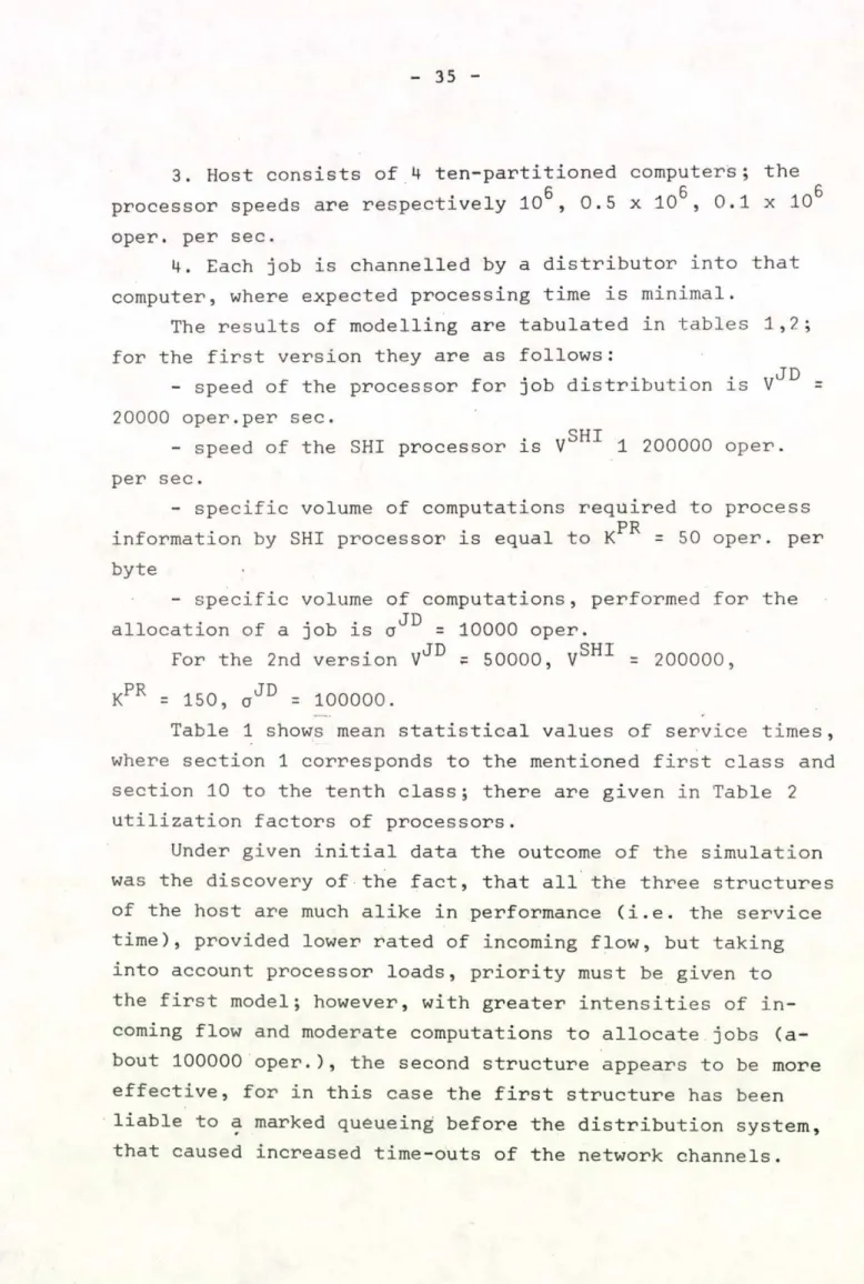
3. Host consists of 4 ten-partitioned computers; the
g 0 0
processor speeds are respectively 10 , 0.5 x 10 , 0.1 x 10 oper. per sec.
4. Each job is channelled by a distributor into that computer, where expected processing time is minimal.
The results of modelling are tabulated in tables 1,2;
for the first version they are as follows:
- speed of the processor for job distribution is V ^ D = 20000 oper.per sec.
OUT
- speed of the SHI processor is V 1 200000 oper.
per sec.
- specific volume of computations required to process information by SHI processor is equal to К PR = 5 0 oper. per byte
- specific volume of computations, performed for the allocation of a job is = 1 0 0 0 0 oper.
For the 2nd version VJD = 50000, VSHI = 200000, KPR = 150, aJD = 100000.
Table 1 shows mean statistical values of service times, where section 1 corresponds to the mentioned first class and
section 10 to the tenth class; there are given in Table 2 utilization factors of processors.
Under given initial data the outcome of the simulation was the discovery of the fact, that all the three structures of the host are much alike in performance (i.e. the service time), provided lower rated of incoming flow, but taking into account processor loads, priority must be given to the first model; however, with greater intensities of in
coming flow and moderate computations to allocate jobs (a- bout 1 0 0 0 0 0 oper.), the second structure appears to be more effective, for in this case the first structure has been liable to a marked queueing before the distribution system, that caused increased time-outs of the network channels.
36
And finally the third structure is to be used when large computations are performed for distribution ( 1 0 0 0 0 0 oper.
and more).
5. CONCLUSIONS
The studies, performed have shown, that efficient p e r formance of multicomputer host within the distributed net
work is substantially dependent on the allocation of fore
man services among the host computers. Applying the principles of program simulation, based on the theory of piecewise
linear aggregates and the method of control sequences has demonstrated their efficiency in creating models of compli
cated computer system (computer complexity); this is because they allow to present the whole system as its individual interacting subsystem^, for each of which a program model can be constructed by a standard technique.
REFERENCES
1. Ю.Б. Башин: Вопросы диспетчеризации информационно-вычисли
тельных работ в ГСВЦ. Тезисы докладов к Международной науч
но-технической конференции ученых и специалистов стран-чле
нов СЭВ и СФРЮ по проблеме: "Организация управления социалис
тическим промышленным производством". Серия № 6 "Техника и технология управления", часть II, М., 1975.
2. Ю.Б. Башин, В.А. Ильин: Информационные сети с ЭВМ. Знание, М., 1976.
3. L. Kleinrock: Analytic and simulation methods in computer design, SSCC, 1970, p p . 569-579.
4. Ю.П. Зайченко: Исследование операций. Издательское объедине
ние "Виша школа", Головное издательство, Киев, 1975-
5. Н.П. Бусленко, В.В. Калашников, И.Н. Коваленко: Лекции по теории сложных систем. М., "Советское радио", 1975.
6. В.Н . Бусленко, Н.П. Бусленко, В.В. Калашников, В.И. Лутков:
Имитационная модель агрегативной системы. Программирование, 1975, № 1, М., "Наука", стр. 60-71.
7. А.И. Волков, П.П. Живаткаускас, Г.И. Праневичюс: Применение метода управляющих последовательностей для описания функцио
нирования мультипрограммной ЭВМ. Материалы конференции "Раз
витие технических наук в республике и использование их резуль
татов", Каунас , 1975, стр. 11-19.
Y. Bashin, I. Gorelik, H. Pranevitchius Kaunas Politechnical Institute
Lithuana USSR
TABLE 1
VARIANT MODEL
TOTAL RATE OF REQUEST (REQ./SEC)
= 0.06 = 0.15 -0.18
SEC. 1 SEC. 10 S E C .1 SEC.10 S E C . 1 SEC.10
I
II
1 2.68 82.7 3.04 139.1 3.76 175.0
2 2.76 81.4 3.28 148.6 3.54 169.8
3 3.15 83.0 3.82 140.0 4.05 178.2
1 3.92 90.0 6.85 142.1 7.36 177.3
2 3.34 88.2 5.58 146.0 5.85 173.0
3 4.12 92.1 8.68 147.4 8.95 178.6
VARIANT MODEL
UTILIZATION FACTOR OF EQUIPMENT CPU1 c p u2
CPU3 CPU^ СР SP
1 0.715 0.613 0.562 о о
Э.131 -
I 2 0.799 0.618 0.2 30 0.199 0.118 -
3 0.756 0.698 0.327 0.001 0.117 0.075
1* 0.747 0.646 0.36 5 о • о
0.428 -
II 2 0.752 0.659 0.454 о о
0.352 -
3 0.752 0.629 0.453 о о
0.353 О ГО
this case a considerable increasing of queue for scheduling requests occurs
COMMUNICATION CHANNELS.
0
S T
1
*
SOFTWARE/
/HARDWARE INTERFACE
*
SPECIAL-PUR POSE MINI
COMPUTER
INFORMATION BUSES
Fig.3. Host Structure III
CONTROL BUSES
EXTERNAL STORAGE INFORMATION
MODULE
. MODULE 1
MODULE 2 fafer
* MODULE m
COMPUTER 1
COMPUTER 2
■9 COMPUTER ш
COMMUNICATION
COMMUNICATION
3 * — * W i*—
S f — CJ
SOFTWARE/
/HARDWARE INTERFACE
INFORMATION BUSES
Fig.2. Host Structure II
CONTROL BUSES
AN INTEL 8080 BASED MULTITASK SUPERVISOR Peter Bernus
Hungary
Abstract
The multitask environment maintained by the supervisor described is intended for application in realtime
controllers which have to perform more or less in
dependent functions and a convenient way to write the controller's program is the multitask approach.
The paper presents how the structured analysis method SADT has improved the design and the implementation of the system.
SADT is a Trade Mark of Sof Tech Inc. Waltham, Mass. USA
46
Requirements
This Multitask Supervisor /MTSV/ was intended to be used in realtime controllers, built up on Intel 8 0 8 0 base - where a convenient approach to write the con
troller's program is the multitasks one.
A typical task is for instance to control a material
handling subsystem of an Integrated Manufacturing System.
Parallel tasks can be for instance:
- to control a mechanical palet changer equipment through a serial 1/0 line
- to perform a dialog with a worker through keyboard and alphanumeric display
- to send sometimes status reports to a central computer
- to control the sequence of other slow mechanical eq u i p m e n t .
The requirements such a supervisor should meet are listed on Fig.l. The MTSV should be an independent software
component, so that you can run your machine code level programs /here called tasks/ on both dedicated hardware and on a hardware shared between tasks by the help of the MTSV. The Second independency requirement is the independency of the SV from I/O, resulting in the transportability of the SV between different micro
computer configurations. The SV has to support the distribution of tasks between processors i.e. when the programmer is writing his tasks, he or she is not forced to keep in mind on which actual processor his or her task will run. Thus, hardware interfaces should remain trans
parent to the task-communication. The only thing to do
inserts a queue-linking interface. /Figures 2 and 3/
The last independency requirement as stated on figure 1.
was the independency of task - I / O from hard-I/O. Th e r e fore I/O tasks work on and/or from 1/0 queues while they change information with IT routines via dedicated tables.
Solution
The diagramming technique SADT was used to determine the functions the MTSV has to perform.
The first decomposition /fig.4./ shows the functions on one processor. The main and only task of the SV is to administer tasks. For this purpose it uses or accesses
. STATUS and STACK information . a TASKTABLE
. TIMER interrupts . QUEUES' STATUS
The ADMINISTER J TASK function is divided into subfunc
tions in a perfect and disjunt way as shown on f i g . 5.
Arrows representing those and only those data /-classes/
enter the block of ADMINISTER TASKS, which did it on its parent diagram A 0. There is .a similar rigorous correspondence between controlling data and output data respectively. A further decomposition of block N o . 2. of this actigram is shown on figure 6. This is the actigram of the function "SCHEDULE".
Block N o .1. on this figure - which is seen to be activated by IT1 or a simulated interrupt - represents the first action to be performed by the MTSV. It is clearly shown
48
t h a t t h e c u r r e n t s t a t u s i s s a v e d o n t o t h e stack
/being p a r t o f t h e s t a c k s / a n d t h e a c t u a l task-state and S t a c k p o i n t e r i n f o r m a t i o n a r e s a v e d i n t o t h e task- table .
The function makes also use of the pointer depicting the current tasktable-entry.
Characteristics /summarized on table 7./
The MTSV supposes the presence of an interrupting hardware timer device which clocks every 1 msecond and enables the supervisor to change tasks continu
ously. The same clock is used for measuring the elapsed time of "sleeping tasks".
Another timer with 10 msec, interval is used for the maintenance of a realtime-register. Every task can use an alarm-clock of his own and be woken up at the desired time by the MTSV.
Information flow between tasks and hardware as well as intertask communication is maintained via message queues. A common, uniform queue area handling subroutine package is the base stratum of the MTSV. However this task-turnaround administration is made through additional tasktable. This is due to time considerations. When using a 1 msec timer and running 8 parallel tasks on an
Intel 8080 the MTSV overhead is about 27 p.c.
An actual system's generation requires the addition of peripheral driver subroutines to the MTSV, which are supplied from output queues or supply input queues with input data respectively. Every task has a queue- -number /or can have it/ and a task number. The queue- number, if any, must be equal to the task number.
Every task has a dedicated stack area used for subroutine
calls and parameter passing as well as temporary data storage.
Tasks can put 16 bit data into and get from any queue.
A task can require the MTSV to let him sleep until it's input queue /or another specified one/ is not empty.
The states a task can have under MTSV are shown on fig.8 together with possible transitions. Transitions are initiated either by the MTSV or through MTSV p r i mitives.
MTSV primitives:
STOP; calling task stops.
STOPTS n ; stops n'th task except if it is the running one /itself/
ABORTS n ; aborts n'th task. The current value of the Stackpointer of the aborted task is saved into the tasktable.
ABORT ; aborts calling task.
WCY; makes the calling task wait a task-turnaround
* t i m e .
RUNTS n ; if the n'th task was in "STOPPD" state, it will enter the WCY state.
WY T ; the calling task enters the WY state and will be woken up after T milliseconds will have elapsed.
WRT LOC RT ; the calling task enters the WRT state e.g.
it waits until the mask-value referred by the parameter RT of the primitive call becomes smaller than the value of the MTSV's realtime register.
WQ n ; the calling task enters the WQ state and will be woken up if the n'th queue is not empty. Typically
50
a task waits for his own input queue. If in the moment the task calls WQ the n'th queue is not empty the WQ n call gives control back to the calling task without any delay.
WHOAMY n; this is a feature of the MTSV which enables the programmer to write reentrant subroutines which are parallelly used by several tasks. This
is the way such a subroutine can decide under which task he is actually running.
GIVERT LOC RT ; the MTSV copies the contents of the realtime registers into the area pointed to by the primitive call's RT parameter.
The areas under the MTSV's responsibility are shown on fig.9. These are
. Realtime registers . tasktable
. current tasktable entry /pointer/
As mentioned earlier there is a stratum between the hard
ware level and the MTSV. This is the queue area handling one /fig.lo/./We don't deal here with the IT routines./
Queue area handling
• The queue area handling can be considered from two
aspects. The one is as the free area management sees it /fig.11/. Here, there is a double pointer free area chaining/handling. This is the base of the fact, that the system uses only one common queue area which is used as a resource of memory cells. Due to this only the sum of the length of the queues is limited.
The other aspect /fig.12/ of the queue area handling
is as the queue routines see it.
There exists an array of queue entry /IN/ pointers and another for queue-end pointers /OUT/. The first is used by the GETQ , the second by the PUTQ
routines. Queue routines - being common and not share
able - run under IT disable. The pessimum of running times is given on the figure.
Conclusion
A multitask supervisor for use in realtime controllers without extreme requirements in speed has been presented.
Special attention was given to the structured design and analysis method which enabled us to design and implement this MTSV within as short as 3-4 weeks
including design, coding and debugging. The relatively low evaluation time has proven the efficiency of the
method and convinced us of the necessity using structured methods for specifying and coding. However coding was done in assembly language the longest part of the code which has not been designed in SADT before was about
5o bytes long.
- 52
- TABLE 1 -
M T S V : MULTITASK SUPERVISOR
REQUIREMENTS:
THE MTSV SHOULD BE INDEPENDENT OF OTHER SYS COMPONENTS
. MACHINE CODE LEVEL PROGRAMS ARE TO RUN ON BOTH DEDICATED AND M U L T I - -HARDWARE
. I/O AND MULTITASK HAS TO BE INDEPENDENT
. THE MTSV IS CONCERNED WITH A TOOL ENABLING US TO ASSIGN PARALLEL TASKS TO A SET OF DISTRIBUTED P R O CESSORS.
. INTERTASK COMMUNICATION AND I/O SHOULD BE UNIFORM . I/O TASKS WORK ON A N D / O R FROM QUEUES AND CHANGE
INFO W I T H IT ROUTINES VIA DEDICATED TABLES
QUEUE LINKING INTERFACE
Processor No. 1. Processor No. 2.
Figure 3
INPUTDATA
54
ALLOCATE TASKS TO PROCESSORS
Figure 2
DEDICATEDOUTPUT
SATD™Afl ACTIGRAM OF THE MTSV RUNNING ON ONE PROCESSOR
Status, Data-Area, TM of Softech. Waltham, Mass. USA
Figure 4
MTSV-A2 ACTIGRAM ADMINISTER TASKS
Figure 5
STACKS
Figure 6
- 58 - TABLE 7 -
C H A R A C TERISTICS
. 1 msec timer, change tasks sleeping tasks . 10 msec timer, realtime register . message queues
. queue handling package . tasktable.
ex :
INTEL 8 0 8 0, 8 tasks, 1 msec timer . overhead : 27 p.c.
. task/s/: dedicated input queues V Application area - small
- sophisticated control
- no strong time requirements
TASK-STATES AND STATE TRANSITIONS
Figure 8
60
AREAS WITHIN THE MTSV'S RESPONSIBILITY REALTIME REGISTER(TT.RT)
HOURS SECONDS MILLISECONDS
О 15 О 15 О 15
CURRENT TASKTABLE ENTRY (TT.CTE)
F i g . 9
MTSV STRATA
Q U E U E AREA HARDWARE 1HANDLING
PERFORM TASKS MTSV
TASK ADMINISTRATION
Figure 10
62
Qu e u e a r e a h a n d l i n g
FIRST PLACE NEVER USED
UNUSED
UNUSED
UNUSED
Figure 11