This article has been accepted for inclusion in a future issue of this journal. Content is final as presented, with the exception of pagination.
IEEE TRANSACTIONS ON MAGNETICS 1
Efficient Perturbation Method for Computing Two-Port Parameter Changes Due to Foreign Objects for WPT Systems
József Pávó 1, Zsolt Badics 2, Sándor Bilicz 1, and Szabolcs Gyimóthy1
1Department of Broadband Infocommunications and Electromagnetic Theory, Budapest University of Technology and Economics, 1111 Budapest, Hungary
2Tensor Research, LLC, Andover, MA 01810 USA
The change in the two-port parameters of a wireless power transfer (WPT) chain is evaluated when an object (foreign object) with given material parameters is placed in the vicinity of the WPT transmitter and receiver. An integral formula for the change of the two-port parameters due to the presence of a foreign object has been derived by using the generalized theory of reciprocity.
It is emphasized that—instead of taking the differences of the two-port parameters calculated with and without the presence of the foreign object—the presented method provides the change of the two-port parameters directly from the calculated electromagnetic field at the location of the foreign object. As a result, the relatively small parameter changes can be predicted with good accuracy.
Based on the application of the Born approximation, the possibility of computing an approximation of the changes of the two-port parameters is explored.
Index Terms— Born approximation, foreign object detection, reciprocity principle, wireless power transfer (WPT).
I. INTRODUCTION
A
CCURATE and fast prediction of the interaction between a wireless power transfer (WPT) system and a foreign object is frequently required during the design and operation of such devices. Usually, the voltages and currents at the two poles of the transmitters and receivers are measured and these data are used by the control system of the WPT chain to detect the foreign object [1], [2]. As the changes of the two-port values are very small compared with their nominal values, usually these changes are measured directly.The calculation method presented in this paper computes the changes of the two-port characteristics compared with their nominal values directly, consequently providing a numerically robust and accurate method to predict the data used for the control of the WPT system.
First, an integral formula for the impedance changes based on the general theory of reciprocity [3] is derived. In this paper, we present the derivation for two-port impedance char- acteristics but one can obtain analogous expressions for any other two-port characteristics similar to the impedance-change derivation. A similar idea has been pursued for eddy-current nondestructive evaluation and full-wave WPT problems in [4]
and [5], which has also introduced an efficient method, the so-called perturbation method, in order to provide a fast and an accurate way of computing the field perturbation due to the foreign object. The perturbation method has been generalized further for a wide range of low-frequency appli- cations in [6]. Although utilizing the perturbation method provides extensive run-time improvement compared with the total field computation, it would be desirable to come up
Manuscript received June 27, 2017; accepted November 1, 2017.
Corresponding author: J. Pávó (e-mail: pavo@evt.bme.hu).
Color versions of one or more of the figures in this paper are available online at http://ieeexplore.ieee.org.
Digital Object Identifier 10.1109/TMAG.2017.2771511
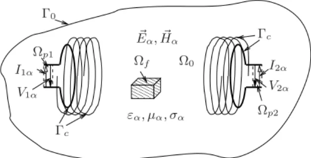
Fig. 1. Two configurations for deriving impedance change formulas. Config- uration A: without the presence of the foreign object in volumef,α=a.
Configuration B: with the presence of the foreign object in volumef,α=b.
with further speed improvement when computing impedance changes for the WPT control loops even if we sacrificed some accuracy.
Thus, based on the use of the Born approximation [7], the possibility of evaluating the impedance changes requiring only the calculation of the electromagnetic field without the presence of the foreign object is explored. A simple example is studied to investigate the range of the applicability of the Born approximation numerically using the finite element method (FEM). Finally, using a fast calculation method based on integral equations [8], the changes of the impedance characteristics of a WPT chain is evaluated while a foreign object (a dielectric sphere) is moved between the transmitter and receiver.
II. IMPEDANCE-CHANGEFORMULA BYRECIPROCITY
A. Configurations
Let us consider the two WPT configurations (Configura- tions A and B) shown in Fig. 1. Subscripts a and b denote the electric, E, and magnetic, H , field components and material parameters (permeabilityμ, permittivityε, and conductivityσ) associated with the Configurations A and B, respectively.
0018-9464 © 2017 IEEE. Personal use is permitted, but republication/redistribution requires IEEE permission.
See http://www.ieee.org/publications_standards/publications/rights/index.html for more information.
This article has been accepted for inclusion in a future issue of this journal. Content is final as presented, with the exception of pagination.
2 IEEE TRANSACTIONS ON MAGNETICS
The time variation of the electromagnetic field is considered to be the real part of ejωtwhereωdenotes the angular frequency of the excitation and t stands for the time.
In both the configurations, the WPT chain is embedded in linear material. The outer boundary, 0, of the investigated volume,0, is far from the WPT system and it extends well into the free space. The metallic wires of the WPT coils are excluded from 0 and the surface of the wires are denoted by c.
The WPT chain is terminated by two poles of which the cur- rents and voltages are denoted by I1a and I2a, and V1a and V2a
(in Configuration A) or I1b and I2b, and V1b and V2b
(in Configuration B). The small volumes of the ports, p1 and p2, are between the poles of ports 1 and 2, respectively.
The two configurations are almost identical, except: 1) the material properties of the two configurations in volumef are different; 2) the feeding currents of the terminals I1a and I2a, I1b and I2b and the terminal voltages V1a, V2a, V1b, and V2b
are different.
B. Computation of Impedance Changes
The Maxwell equations associated with Configurations A and B are
∇ × Ha = Jai +jω˜εaEa, ∇ × Ea= −jωμaHa (1)
∇ × Hb = Jbi +jω˜εbEb, ∇ × Eb= −jωμbHb (2) where ε˜a = εa − jσa/ω and ε˜b = εb − jσb/ω are the complex permittivities. Jai and Jbi are the current densities in p1 and p2 representing the port currents at the different configurations.
Following similar algebra used for the derivation of the generalized concept of reciprocity in [3], we obtain:
c+0
(Eb× Ha− Ea× Hb)d
=
p1
(Ea· Jbi− Eb· Jai)d+
p2
(Ea· Jbi − Eb· Jai)d
−
f
jω[(μb−μa)Ha· Hb−(˜εb− ˜εa)Ea· Eb]d. (3) The left-hand side of (3) is zero because for both config- urations, the same boundary conditions setting the ratio of the E and H apply (on 0 the radiation condition and on c the impedance-type boundary condition). Consequently, the two terms of the integrand will be equal. The first and the second integrals of the right-hand side can be expressed by the port currents and voltages. We assume that in the volumes, p1 andp2, E is homogeneous. Thus, we can write
p1
Ea· Jbid=I1b
p1
Eadl= −I1bV1a (4) where p1 is any line between the two poles of port 1. The remaining parts of the first two integrals of the right-hand side of (3) can be obtained similarly. As a result, we arrive at the
following equation:
I1bV1a−I1aV1b+I2bV2a−I2aV2b
= −
f
jω[(μb−μa)Ha· Hb−(˜εb− ˜εa)Ea· Eb]d. (5) The two-port impedance characteristics associated with Configurations A and B can be written as
V1a = Z11I1a+Z12I2a (6) V2a = Z21I1a+Z22I2a (7) V1b =(Z11+ Z11)I1b+(Z12+ Z12)I2b (8) V2b =(Z21+ Z21)I1b+(Z22+ Z22)I2b (9) where Z11, Z12, Z21, and Z22are the impedance parameters of the two-port, describing the WPT chain without the presence of the foreign object. Z11, Z12, Z21, and Z22 are the changes of the corresponding impedance parameters due to the presence of the foreign object. Our goal is to find a robust formula for the computation of these changes. Note that the reciprocity of the arrangement assures that Z12 ≡ Z21 and Z12≡ Z21.
Let us multiply (6)–(9) with I1b, I2b, I1a, and I2a, respec- tively, and plug them into (5)
Z11I1aI1b+ Z22I2aI2b+ Z12(I1aI2b+I1bI2a)
=
f
jω
(μb−μa)Ha· Hb−(˜εb− ˜εa)Ea· Eb
d. (10) The actual Z11, Z22, and Z12 values can be obtained directly by evaluating the right-hand side of (10) for three linearly independent combinations of the currents. Then, this linear system can be solved for the derived impedance changes.
III. BORNAPPROXIMATION
For the sake of simplicity, let us assume that σa = σb
and μa = μb. Then, based on the first-order Born approx- imation [7], Eb in (10) can be approximated by Ea if the permittivity of volume f in Configuration B is close to the one in the case of Configuration A and if the same port currents are used for Configurations A and B, i.e., I1a = I1b = I1 and I2a=I2b =I2. For this situation, we have Z11I12+ Z22I22+2 Z12I1I2≈−
f
jω(εb−εa)Ea2d.
(11) Consequently, we can conclude that—by knowing the electric field, Ea, in the volume f calculated without the presence of the foreign object—one can get an approximation of the impedance changes due to the presence of the foreign object by evaluating the integral (11). This can be done if the conditions necessary for the validity of the first-order Born approximation are satisfied. In the following numerical example, we compare the results based on the Born approximation with the ones obtained from the exact formula (10).
If the permittivity differences between the configurations are larger, one may use higher order Born approximations [9]
This article has been accepted for inclusion in a future issue of this journal. Content is final as presented, with the exception of pagination.
PÁVÓ et al.: EFFICIENT PERTURBATION METHOD FOR COMPUTING TWO-PORT PARAMETER CHANGES 3
TABLE I
PARAMETERS OF THEWPT CONFIGURATION
to get a good prediction of the impedance parameter changes based on Ea. As a result, the impedance variation and the Ea field can also be linked together for larger permittivity differences.
The impedance variation due to the presence of a conducting and/or magnetic foreign object can also be obtained by the Born approximation in a similar way starting from (10) if the necessary conditions hold.
IV. NUMERICALEXAMPLES
We investigate a symmetric WPT system with identical transmitter and receiver units, both of them consisting of a helix coil and a matching loop, respectively (see Fig. 2). The parameters of the configuration are summarized in Table I.
The base plane of the helix is parallel with the plane of the loop. The power transfer is “corrupted” by a foreign object, which is represented here by a dielectric sphere. Coils, loops, and the sphere are all in a coaxial alignment and surrounded by air.
The coil terminals are open (self-resonating coils), while both loops are interrupted by small gaps (not shown) that are considered as the lumped ports of a two-port. In normal operating conditions, the transmitter port is connected to an ac source and a passive load is connected to the receiver port.
Note that the dielectric constant of the sphere, its axial (z) position, and the applied frequency are variable parameters.
A. Input Impedance Change of the WPT Transmitter
In the first step, the applicability of the Born approximation is studied using the FEM. The choice of FEM is justified by the fact that the modeling of dielectric objects by FEM is more straightforward than with other methods, e.g., the method of moments (MoM).
For this study, the input impedance of the transmitter is calculated in the absence of the receiver, but impedance is still perturbed by the presence of the dielectric sphere.
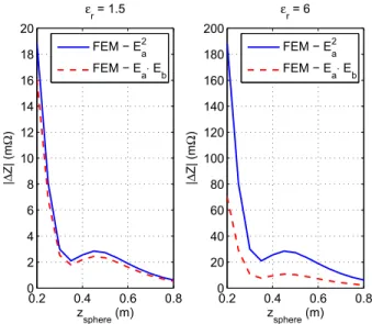
Computations were carried out for two different permittivity values of the sphere: εr = 1.5 and εr = 6, and the axial position of the sphere was varied. The applied frequency is 9 MHz.
According to (10), the change of the input impedance due to the sphere can be calculated as
Z= −
sphere
jωε0(εr −1)Ea· Ebd (12)
Fig. 2. Model of a WPT system “corrupted” by a foreign object.
Bottom: transmitter unit. Top: receiver.
Fig. 3. Change of the input impedance (magnitude) of the WPT transmitter due to a dielectric sphere, as a function of its position, for two different dielectric constants. The dashed curve refers to (12) and the solid curve to its approximation (13). Note that zsphere denotes the z-coordinate of the sphere center, and z=0.2 m corresponds to the top end of the transmitter coil (see Fig. 2).
whereas the utilization of the Born approximation (11) yields Z ≈ −
sphere
jωε0(εr −1)E2ad. (13) Fig. 3 provides a comparison of the integrals (12) and (13) evaluated by the FEM. Only the magnitude of Z is plotted, because the difference in phase change turns out to be neg- ligible. Obviously, the proposed approximation is acceptable for lower permeability contrasts only.
B. Impedance Changes of the WPT System
In the next step, we compute the perturbation of the two- port impedance parameters of the whole WPT chain (Fig. 2)
This article has been accepted for inclusion in a future issue of this journal. Content is final as presented, with the exception of pagination.
4 IEEE TRANSACTIONS ON MAGNETICS
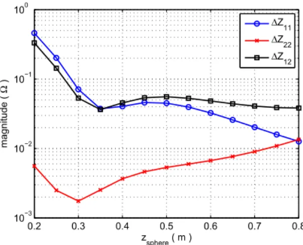
Fig. 4. Perturbation of the impedance parameters of the WPT system due to a dielectric sphere as a function of its position. The frequency is 10 MHz.
Fig. 5. Perturbation of the impedance parameters of the WPT system due to a dielectric sphere as a function of the frequency. The position of the sphere is fixed at zsphere=0.2 m.
due to the presence of a dielectric sphere of low permeability, εr = 1.5. Owing to this permeability value, one can safely rely on the approximate formula (11). This also allows using more efficient numerical methods, such as MoM [8], because the knowledge of Eb(the field in the presence of the dielectric object) is not needed any longer.
Fig. 4 shows the magnitude of the impedance change versus the position of the sphere as resulted using MoM. The applied frequency is 10 MHz. Note that zsphere=0.8 m corresponds to the midpoint between the transmitter and the receiver, and
Z11= Z22 holds as it is expected.
The magnitude of the impedance change versus the fre- quency is plotted in Fig. 5. In this case, the position of the sphere is fixed at zsphere = 0.2 m. It can be observed that in OFF-resonance, the parameter Z22 is hardly affected by the dielectric object being much closer to the transmitter than to the receiver. On the other hand, near the resonance frequency ( f0≈10.4 MHz), where effective power transfer
takes place, the receiver “can see” the object on the other side as the higher value of Z22 shows.
V. CONCLUSION
An integral formula giving the change of the two-port impedance characteristics of a WPT chain is evaluated based on the generalized theory of reciprocity. The main advantage of the derived formula is that the change of the impedance parameters is evaluated directly from the electromagnetic field at the location of the foreign object. Consequently, even very small variations can be obtained with high accuracy. The application of the first-order Born approximation is considered in the proposed calculations. If this can be used, one needs to calculate only the electromagnetic field of the WPT chain without the presence of the foreign object. By a simple numerical example, the range of the applicability of the first- order Born approximation is investigated by the FEM. It was found that one can use this approximation only for small contrasts. In the future, other approximations, e.g., higher order Born approximations, are planned to be considered to extend the range of the applicability of the simple technique.
ACKNOWLEDGMENT
This work was supported in part by the Hungarian Scientific Research Fund under Grant K-111987 and in part by the János Bolyai Research Scholarship of the Hungarian Academy of Sciences.
REFERENCES
[1] Y.-C. Wang and C.-W. Chiang, “Foreign metal detection by coil impedance for EV wireless charging system,” in Proc. EVS28 Int. Electr.
Vehicle Symp. Exhib., Goyang, Korea, May 2015, pp. 3–6.
[2] P. Zhang, Q. Yang, X. Zhang, Y. Li, and Y. Li, “Comparative study of metal obstacle variations in disturbing wireless power transmission system,” IEEE Trans. Magn., vol. 53, no. 6, pp. 1–4, Jun. 2017.
[3] R. F. Harrington, Time-Harmonic Electromagnetic Fields. New York, NY, USA: McGraw-Hill, 1961.
[4] Z. Badics, Y. Matsumoto, K. Aoki, F. Nakayasu, M. Uesaka, and K. Miya, “An effective 3-D finite element scheme for computing electromagnetic field distortions due to defects in eddy-current nonde- structive evaluation,” IEEE Trans. Magn., vol. 33, no. 2, pp. 1012–1020, Mar. 1997.
[5] Z. Badics, S. Bilicz, S. Gyimóthy, and J. Pávó, “Finite-element-integral equation full-wave multisolver for efficient modeling of resonant wire- less power transfer,” IEEE Trans. Magn., vol. 52, no. 3, Mar. 2016, Art. no. 7207904.
[6] P. Dular, R. V. Sabariego, and L. Krähenbühl, “Subdomain perturbation finite-element method for skin and proximity effects,” IEEE Trans.
Magn., vol. 44, no. 6, pp. 738–741, Jun. 2008.
[7] M. Born and E. Wolf, Principles of Optics, 7th ed. Cambridge, U.K.: Cambridge Univ. Press, 1991.
[8] S. Bilicz, S. Gyimóthy, J. Pávó, L. L. Tóth, Z. Badics, and B. Bálint,
“Modeling of resonant wireless power transfer with integral formulations in heterogeneous media,” IEEE Trans. Magn., vol. 52, no. 3, Mar. 2016, Art. no. 7205904.
[9] G. Gao and C. Torres-Verdin, “High-order generalized extended born approximation for electromagnetic scattering,” IEEE Trans. Antennas Propag., vol. 54, no. 4, pp. 1243–1256, Apr. 2006.